


5 of 15
2.1.2 Lens Purge
A 60 SCFH (28 L/min) flow of purge gas to the Steam Jacketed Lens Assembly is required.
Ensure that the supply of purge gas is clean, oil free and dry. Any moisture or hydrocarbons in
this purge gas may cause the inside of the lens window to coat. A coating will prevent some of
the infrared energy from reaching the sensor, causing a low temperature reading to occur, and
window cleaning to be required. Use a flow meter with a needle control valve suitable for a
flow rate of approximately 10 SCFH to 90 SCFH air (0.5 L/min to 41.7 L/min). Connect the
purge gas supply to the 1/8” NPT fitting on the top of the Steam Jacketed Assembly. Regulate
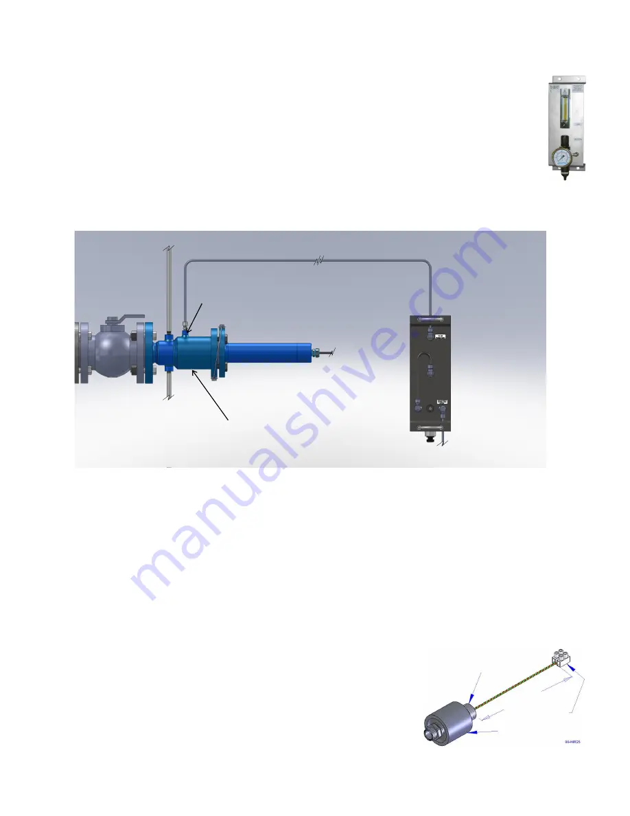
the purge supply to 15 psig (1 bar). Delta Controls recommends using Model HFI Flush Gas
Station (Figure 3) as it provides a conveniently packaged assembly of the necessary purge
supply components. Connection of the Model HFI is shown in Figure 4.
2.2 Thermal Insulation
To prevent sulfur from plugging the optical path, it is important that a temperature above +250
F (+121
C) be
maintained on the nozzle, isolation valve, and Steam Jacketed Lens Assembly. In most cases, the heat from the
reactor and steam body are not sufficient to keep the temperature of the valve and lens assembly above this
temperature unless they are insulated. It is important, therefore, that insulation be installed around the nozzle,
valve, and lens assembly, as shown in Figure 1, in accordance with the best practices of your plant. Adequacy of
the insulation should be tested by verifying that the lens assembly flange and the isolation valve body are above
+250
F (+121
C) under the most unfavorable conditions (wind, rain, snow, etc.)
2.3 Installing the Electronics Housing
A mounting location must be provided nearby for the electronics module.
Choose a location that is protected from the heat of the reactor, such that
the maximum ambient temperature of the electronics is not exceeded. For
convenience in performing optical alignment, the electronics display
should be visible to an operator standing at the Steam Jacketed Lens
Assembly.
To Flush Gas Supply
Purge
Inlet
Model HFI
Flush Gas Station
(Rear View)
Model HIR Steam
Jacketed Assembly
To Steam Trap
To Steam Supply
Figure 4 Purge Connections
Figure 3
Model HFI Flush
Gas Station
½” NPT
6 in (150 mm)
Terminal
Block
Fiber
Optic Adapter
Figure 5 Fiber Optic Adapter


