


40
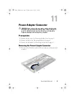
Power-Adapter Connector
4
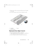
Align the screw hole on the power-adapter connector with the screw hole
on the palm-rest assembly.
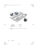
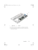
5
Route the power-adapter connector cable through the routing guides.
6
Connect the power-adapter connector cable to the system-board
connector.
7
Replace the screw that secures the power-adapter connector to the palm-
rest assembly.
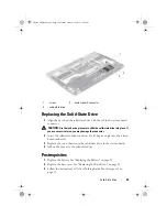
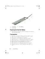
Postrequisites
1
Replace the right speaker. See "Replacing the Speakers" on page 21
2
Replace the battery. See "Replacing the Battery" on page 18
3
Replace the base cover. See "Replacing the Base Cover" on page 14
4
Follow the instructions in "After Working Inside Your Computer" on
page 11.
Connectors on the Mini-Card
Mini-Card Cable Color
Scheme
WLAN + Bluetooth (2 cables)
Main WLAN + Bluetooth (white triangle)
Auxiliary WLAN + Bluetooth (black triangle)
white
black
Spyder_OM_Book.book Page 40 Monday, January 16, 2012 11:02 AM
Summary of Contents for XPS 13
Page 8: ...8 Contents Spyder_OM_Book book Page 8 Monday January 16 2012 11 02 AM ...
Page 12: ...12 Before you Begin Spyder_OM_Book book Page 12 Monday January 16 2012 11 02 AM ...
Page 30: ...30 Solid State Drive Spyder_OM_Book book Page 30 Monday January 16 2012 11 02 AM ...
Page 44: ...44 I O Board Spyder_OM_Book book Page 44 Monday January 16 2012 11 02 AM ...
Page 50: ...50 System Board Spyder_OM_Book book Page 50 Monday January 16 2012 11 02 AM ...
Page 56: ...56 Keyboard Spyder_OM_Book book Page 56 Monday January 16 2012 11 02 AM ...
Page 62: ...62 Display Assembly Spyder_OM_Book book Page 62 Monday January 16 2012 11 02 AM ...
Page 66: ...66 Palm Rest Assembly Spyder_OM_Book book Page 66 Monday January 16 2012 11 02 AM ...


