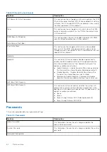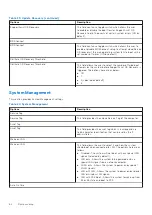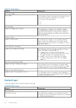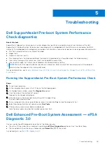
System diagnostic lights
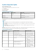
Power-supply diagnostics light
Indicates the status of the power-supply in either of the two sates:
●
Off: No Power
●
On: Power is supplied.
Power button light
Table 29. Power button LED status
Power button LED state
System state
Description
Off
●
S4
●
S5
There is in Hibernate or Off state.
Solid White
S0
Working state
Solid Amber
Various sleep states or No POST
Blinking Amber/White
Failure to POST
This platform relies on the Power button LED light blinking in an amber/white pattern to determine a failure as listed in the
following table:
NOTE:
The blinking patterns consists of two numbers (representing First Group: Amber blinks, Second Group: White blinks).
●
First Group
: The Power button LED light blinks Amber, 1 to 9 times followed by a short pause with LED off for a couple
of seconds.
●
Second Group
: The Power button LED light then blinks White, 1 to 9 times, followed by a longer pause before the next
cycle starts again after a short interval.
.
Example
: No Memory detected (2,3). Power button LED blinks 2-times in Amber followed by a pause, and then blinks 3-times in
White. The Power button LED will pause for few seconds before the next cycle repeats itself again.
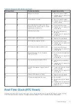
Table 30. Diagnostic LED status
Blinking pattern
Problem description
Suggested resolution
Amber
White
1
1
TPM Detection Failure
●
Replace the system board.
1
2
Unrecoverable SPI flash failure
●
Replace the system board.
1
5
i-Fuse failure: EC unable to program i-Fuse
●
This error is only applicable for
factory testing.
2
1
CPU failure
●
Run the Intel CPU diagnostics
tools.
●
If problem persists, replace the
system board.
2
2
System board failure (including BIOS
corruption or ROM error)
●
Flash latest BIOS version.
●
If problem persists, replace the
system board.
2
3
No memory/RAM detected
●
Confirm that the memory
module is installed properly.
●
If problem persists, replace the
memory module.
70
Troubleshooting
Summary of Contents for Vostro 3890
Page 1: ...Vostro 3890 Service Manual Regulatory Model D29M Regulatory Type D29M004 April 2021 Rev A00 ...
Page 8: ...Major components of your system 1 Side cover 8 Disassembly and reassembly ...
Page 34: ...34 Disassembly and reassembly ...
Page 44: ...44 Disassembly and reassembly ...
Page 47: ...Disassembly and reassembly 47 ...

