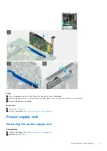
Steps
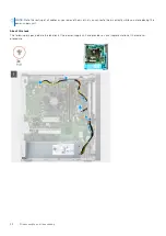
1. Disconnect the power cables from the system board and unroute them from the routing guides on the chassis.
NOTE:
The power-supply cable is connected to the system board at two locations and supply power to the following
components at the two location:
●
Processor - ATX CPU connector
●
System board - ATX SYS connector
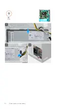
2. Remove the three (#6-32) screws that secure the power-supply to the chassis.
3. Press the securing clip to release the power-supply unit from the chassis.
4. Slide and lift the power-supply unit from its slot on the chassis.
Installing the power-supply unit
Prerequisites
If you are replacing a component, remove the existing component before performing the installation procedure.
WARNING:
The cables and ports on the back of the power-supply unit are color-coded to indicate the different
power wattage. Ensure that you plug in the cable to the correct port. Failure to do so may result in damaging the
power-supply unit and/or system components.
About this task
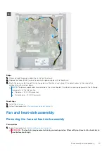
The following images indicate the location of the power-supply unit and provides a visual representation of the installation
procedure.
Disassembly and reassembly
33
Summary of Contents for Vostro 3890
Page 1: ...Vostro 3890 Service Manual Regulatory Model D29M Regulatory Type D29M004 April 2021 Rev A00 ...
Page 8: ...Major components of your system 1 Side cover 8 Disassembly and reassembly ...
Page 34: ...34 Disassembly and reassembly ...
Page 44: ...44 Disassembly and reassembly ...
Page 47: ...Disassembly and reassembly 47 ...


