background image

4.

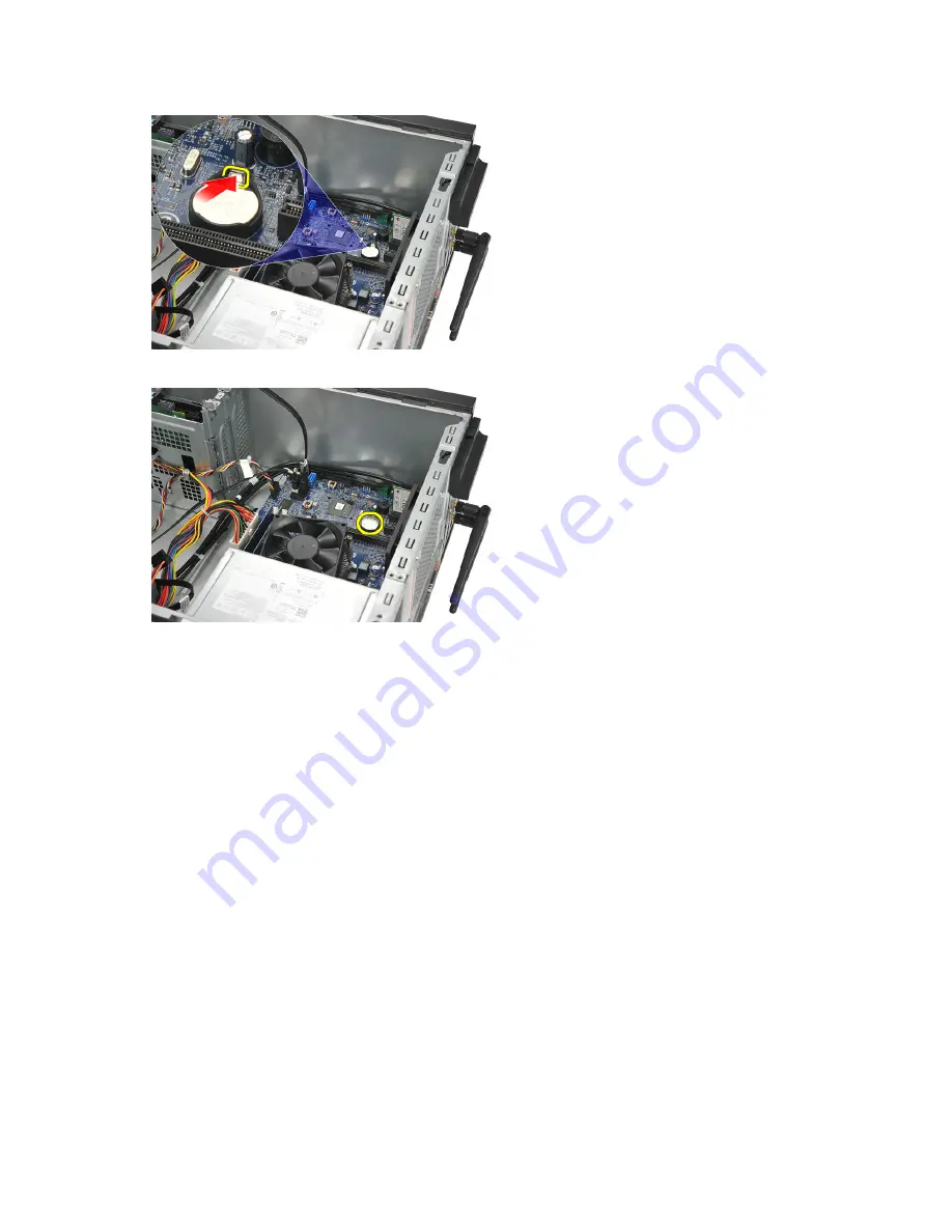
Lift the coin-cell battery out of the computer.

Installing the Coin-Cell Battery

1.

Place the coin-cell battery in it's socket on the system board.

2.

Press the coin-cell battery into the socket till it snaps into place.

3.

Replace the cover.

4.

Follow the procedures in 

After Working Inside Your Computer

.

Removing the System Board

1.

Follow the procedures in 

Before Working Inside Your Computer

.

2.

Remove the:
a) cover
b) memory
c) system fan
d) processor
e) expansion card
f) WLAN card

3.

Disconnect and un-thread all the cables connected to the system board.

24

Summary of Contents for Vostro 270

Page 1: ...Dell Vostro 270 Owner s Manual Regulatory Model D11M Regulatory Type D11M002 ...

Page 2: ...rademarks or trademarks of Intel Corporation in the U S and other countries AMD is a registered trademark and AMD Opteron AMD Phenom AMD Sempron AMD Athlon ATI Radeon and ATI FirePro are trademarks of Advanced Micro Devices Inc Microsoft Windows MS DOS Windows Vista the Windows Vista start button and Office Outlook are either trademarks or registered trademarks of Microsoft Corporation in the Unit...

Page 3: ... Removing the Memory 12 Installing the Memory 12 Removing the Optical Drive 12 Installing the Optical Drive 13 Removing the Hard Drive 14 Installing the Hard Drive 15 Removing the Wireless Local Area Network WLAN Card 15 Installing the Wireless Local Area Network WLAN Card 15 Removing the Card Reader 16 Installing the Card Reader 17 Removing the Power Supply Unit PSU 17 Installing the Power Supply...

Page 4: ...earing Forgotten Password 34 Clearing CMOS Passwords 35 System and Setup Password 36 Assigning a System Password and Setup Password 36 Deleting or Changing an Existing System and or Setup Password 37 Disabling a System Password 37 4 Diagnostics 39 Enhanced Pre Boot System Assessment ePSA Diagnostics 39 5 Troubleshooting 41 Diagnostic Power LED Codes 41 Diagnostic Beep Codes 42 Diagnostic Error Mes...

Page 5: ...urface such as a connector on the back of the computer CAUTION Handle components and cards with care Do not touch the components or contacts on a card Hold a card by its edges or by its metal mounting bracket Hold a component such as a processor by its edges not by its pins CAUTION When you disconnect a cable pull on its connector or on its pull tab not on the cable itself Some cables have connect...

Page 6: ...r Turn Off The computer turns off after the operating system shutdown process is complete 2 Ensure that the computer and all attached devices are turned off If your computer and attached devices did not automatically turn off when you shut down your operating system press and hold the power button for about 6 seconds to turn them off After Working Inside Your Computer After you complete any replac...

Page 7: ...he procedures in this document may require the following tools Small flat blade screwdriver Phillips screwdriver Small plastic scribe Removing the Cover 1 Follow the procedures in Before Working Inside Your Computer 2 Remove the screws that secure the cover to the computer 3 Slide the computer cover towards the back of the computer 4 Remove the computer cover 7 ...

Page 8: ...to the computer 4 Follow the procedures in After Working Inside Your Computer Removing the Front Bezel 1 Follow the procedures in Before Working Inside Your Computer 2 Remove the cover 3 Pry the front bezel retention clips away from the chassis 4 Rotate the bezel away from the computer to release the hooks on the opposite edge of the bezel from the chassis 8 ...

Page 9: ...he tabs snap into place 4 Replace the cover 5 Follow the procedures in After Working Inside Your Computer Removing the Expansion Card 1 Follow the procedures in Before Working Inside Your Computer 2 Remove the cover 3 Press the release tab on the card retention latch 4 Press on the release lever to release the securing tab from the notch in the card 9 ...

Page 10: ... till it snaps into place 2 Secure the expansion card by pushing in the card retention latch till it snaps into place 3 Replace the cover 4 Follow the procedures in After Working Inside Your Computer Removing the System Fan 1 Follow the procedures in Before Working Inside Your Computer 2 Remove the cover 3 Disconnect the fan cable from the system board 10 ...

Page 11: ...om the computer Installing the System Fan 1 Place the fan at it s location on the computer 2 Replace the screws that secure the fan to the back of the computer 3 Connect the fan cable to the system board 4 Replace the cover 5 Follow the procedures in After Working Inside Your Computer 11 ...

Page 12: ...f the connector on the system board Installing the Memory 1 Press the memory module into it s connector on the system board till it snaps into place 2 Replace the cover 3 Follow the procedures in After Working Inside Your Computer Removing the Optical Drive 1 Follow the procedures in Before Working Inside Your Computer 2 Remove the cover 3 Disconnect the data cable and power cable from the optical...

Page 13: ...the computer Installing the Optical Drive 1 Slide the optical drive through the front of the computer 2 Replace the screws that secure the optical drive to the computer 3 Connect the data cable and power cable to the optical drive 4 Replace the cover 5 Follow the procedures in After Working Inside Your Computer 13 ...

Page 14: ...ide Your Computer 2 Remove the cover 3 Disconnect the SATA cable and power cable from the hard drive 4 Remove the screws that secure the hard drive to the computer 5 Remove the hard drive from the computer 6 Remove the screw to release the brackets from the hard drive 14 ...

Page 15: ...cal Area Network WLAN Card 1 Follow the procedures in Before Working Inside Your Computer 2 Remove the cover 3 Disconnect the WLAN cables 4 Remove the screw that secures the WLAN card to the connector 5 Lift and remove the WLAN card from the computer Installing the Wireless Local Area Network WLAN Card 1 Place the WLAN card on its connector and push it in to secure it to the connector 2 Tighten th...

Page 16: ...sconnect the multimedia card reader cable from the system board Disengage the cable from the metal clip s if present that secure s the cable along the inside of the computer 4 Remove the screws that secure the multimedia card reader into the drive cage 5 Slide the multimedia card reader out through the front of the computer 16 ...

Page 17: ...oard 5 Replace the a front panel b cover 6 Follow the procedures in After Working Inside Your Computer Removing the Power Supply Unit PSU 1 Follow the procedures in Before Working Inside Your Computer 2 Remove the cover 3 Disconnect the power supply cables connected to the hard drive s optical drive s and system board 4 Remove the screws that secure the power supply unit to the back of the compute...

Page 18: ... Replace the screws that secure the power supply unit to the back of the computer 4 Connect the power supply cables to the hard drive s optical drive s and system board 5 Replace the cover 6 Follow the procedures in After Working Inside Your Computer Removing the Power Switch 1 Follow the procedures in Before Working Inside Your Computer 2 Remove the cover 3 Disconnect and un thread the power swit...

Page 19: ... computer till it snaps into place 2 Connect the power switch and hard drive LED cable to the system board 3 Replace the cover 4 Follow the procedures in After Working Inside Your Computer Removing the I O Panel 1 Follow the procedures in Before Working Inside Your Computer 2 Remove the cover 3 Disconnect the audio cable and USB cable from the system board 19 ...

Page 20: ...4 Un thread the cable routing from the metal clips 5 Remove the screw that secures the I O panel to the computer 6 Remove the I O panel from the computer 20 ...

Page 21: ...the metal clips 4 Replace the cover 5 Follow the procedures in After Working Inside Your Computer Removing the Processor 1 Follow the procedures in Before Working Inside Your Computer 2 Remove the cover 3 Disconnect the heat sink and fan assembly cable from the system board 4 Loosen the captive screws that secures the heat sink and fan assembly to the system board 21 ...

Page 22: ...it from the computer NOTE Place the assembly with the fan on a flat surface facing downward and with the thermal grease facing up 6 Press down on the release lever to move it outward to release it from the retention hook 7 Lift the processor cover 22 ...

Page 23: ...t 2 Press down on the release lever to lock it with the retention hook 3 Close the processor cover 4 Place the heat sink and fan assembly on the processor 5 Tighten the captive screws securing the heat sink and fan assembly to the system board 6 Connect the heat sink and fan assembly cable to the system board 7 Replace the cover 8 Follow the procedures in After Working Inside Your Computer Removin...

Page 24: ...ery into the socket till it snaps into place 3 Replace the cover 4 Follow the procedures in After Working Inside Your Computer Removing the System Board 1 Follow the procedures in Before Working Inside Your Computer 2 Remove the a cover b memory c system fan d processor e expansion card f WLAN card 3 Disconnect and un thread all the cables connected to the system board 24 ...

Page 25: ...system board towards the front of the computer and then carefully tilt it to a 45 degrees angle 6 Lift the system board out of the computer chassis and place it in an antistatic packaging System Board Layout The following image displays the system board layout of the computer 25 ...

Page 26: ...or 11 processor socket 12 processor fan connector 13 memory module connectors DIMM 1 and 2 14 main power connector 15 CMOS clear reset jumper 16 PCI Express mini connector 17 front LED power connector Installing the System Board 1 Place the system board into the computer and then slide it towards the back of the computer 2 Replace the screws to secure the system board to the computer 3 Connect all...

Page 27: ...a memory b system fan c WLAN card d expansion card e processor f cover 5 Follow the procedures in After Working Inside Your Computer 27 ...

Page 28: ...28 ...

Page 29: ...ess System Setup by pressing F2 key Bring up the one time boot menu by pressing F12 key The one time boot menu displays the devices that you can boot from including the diagnostic option The boot menu options are Removable Drive if available STXXXX Drive NOTE XXX denotes the SATA drive number Optical Drive Diagnostics NOTE Choosing Diagnostics will display the ePSA diagnostics screen The boot sequ...

Page 30: ...AUTION Unless you are an expert computer user do not change the settings for this program Certain changes can cause your computer to work incorrectly Enter System Setup 1 Turn on or restart your computer 2 When the blue DELL logo is displayed you must watch for the F2 prompt to appear 3 Once the F2 prompt appears press F2 immediately NOTE The F2 prompt indicates that the keyboard has initialized T...

Page 31: ...current settings Press Enter to make changes to your current settings Press ESC to return to the Dell Diagnostics NOTE Not all settings listed in the Options Field are changeable Dell Diagnostics Appears on the right side of the System Setup window and contains help information about the option selected in Dell Diagnostics Dell Diagnostics Appears below the Dell Diagnostics and lists keys and thei...

Page 32: ...umber and capacity of the hard drive SATA 1 SATA 2 SATA 3 Table 6 Advanced CPU Configuration Hyper threading Enable or disable processor hyper threading Default Enabled Limit CPUID Value Enable or disable the Limit CPUID Value feature Default Enabled CPU XD Support Enable or disable the CPU XD feature Default Enabled Intel Virtualization Technology Enable or disable the Intel Virtualization featur...

Page 33: ...ring POST Default Enabled Table 7 Boot Set Boot Priority Specifies the order of different devices in which the computer will boot through at start up Hard Disk Drives Specify which hard drive the computer can boot through CD DVD ROM Drives Specify which CD DVD optical drives the computer can boot through Table 8 Security Unlock Setup Status Specifies whether the BIOS can be edited Admin Password S...

Page 34: ...7 Select your preferred download method in the Please select your download method below window click Download Now The File Download window appears 8 Click Save to save the file on your computer 9 Click Run to install the updated BIOS settings on your computer Follow the instructions on the screen Clearing Forgotten Password The computer s software security features include a system password and a ...

Page 35: ... Working Inside Your Computer 2 Remove the cover 3 Identify the CMOS password reset jumper on the system board see the System Board Layout 4 Remove the 2 pin jumper plug from pins 2 and 3 and fix it on pins 1 and 2 5 Install the cover 6 Connect the computer to the electrical outlet and power on the computer to clear the password 7 Power off the computer and disconnect the power cable from the elec...

Page 36: ...assword and Setup Password You can assign a new System Password and or Setup Password or change an existing System Password and or Setup Password only when Password Status is Unlocked If the Password Status is Locked you cannot change the System Password NOTE If the password jumper is disabled the existing System Password and Setup Password is deleted and you need not provide the system password t...

Page 37: ...word Status is Unlocked 3 Select System Password alter or delete the existing system password and press Enter or Tab 4 Select Setup Password alter or delete the existing setup password and press Enter or Tab NOTE If you change the System and or Setup password re enter the new password when promoted If you delete the System and or Setup password confirm the deletion when promoted 5 Press Esc and a ...

Page 38: ...utlet 8 Remove the cover 9 Replace the PSWD jumper on the system board 10 Install the cover 11 Follow the procedures in After Working on Your Computer 12 Power on the computer 13 Go to the system setup and assign a new system or setup password See Setting up a System Password 38 ...

Page 39: ... provide extra information about the failed device s View status messages that inform you if tests are completed successfully View error messages that inform you of problems encountered during testing CAUTION Use the system diagnostics to test only your computer Using this program with other computers may cause invalid results or error messages NOTE Some tests for specific devices require user int...

Page 40: ...40 ...

Page 41: ...a lamp Blinking Amber Computer fails to complete POST or processor failure Remove and then reinstall any cards Remove and then reinstall the graphics card if applicable Ensure the power cable is connected to the motherboard and processor Steady Amber Computer is in standby or this is a computer fault error condition including the power supply Only the 5VSB rail on the power supply is working corre...

Page 42: ... failure 4 RAM Read Write failure Memory failure 5 RTC Power Fail COMS battery failure 6 Video BIOS Test failure Video card failure 7 Processor failure Processor failure Diagnostic Error Messages Error Messages Description AUXILIARY DEVICE FAILURE The touch pad or external mouse may be faulty For an external mouse check the cable connection Enable the Pointing Device option in the system setup pro...

Page 43: ...ames GATE A20 FAILURE A memory module may be loose Reinstall the memory modules and if necessary replace them GENERAL FAILURE The operating system is unable to carry out the command The message is usually followed by specific information For example Printer out of paper Take the appropriate action HARD DISK DRIVE CONFIGURATION ERROR The computer cannot identify the drive type Shut down the compute...

Page 44: ...g the keyboard or the mouse during the boot routine Run the Keyboard Controller test in the Dell Diagnostics KEYBOARD DATA LINE FAILURE For external keyboards check the cable connection Run theKeyboard Controller test in the Dell Diagnostics KEYBOARD STUCK KEY FAILURE For external keyboards or keypads check the cable connection Restart the computer and avoid touching the keyboard or keys during th...

Page 45: ...or on the hard drive You may have a defective sector or corrupted FAT on the hard drive Run the Windows error checking utility to check the file structure on the hard drive See Windows Help and Support for instructions click Start Help and Support If a large number of sectors are defective back up the data if possible and then reformat the hard drive SEEK ERROR The operating system cannot find a s...

Page 46: ...fan has failed Hard disk drive failure Possible hard disk drive failure during POST Keyboard failure Keyboard failure or loose cable If reseating the cable does not solve the problem replace the keyboard No boot device available No bootable partition on hard disk drive the hard disk drive cable is loose or no bootable device exists If the hard drive is your boot device ensure that the cables are c...

Page 47: ...ron L2 cache up to 6 MB depending on the processor Memory Memory module connector two DIMM slots Memory module capacity 2 GB 4 GB 6 GB or 8 GB Type 1333 MHz and 1600 MHz DDR3 Non ECC Minimum memory 2 GB Maximum memory 8 GB Video Video Type Integrated Intel HD Graphics with Intel Pentium Dual Core CPU GPU combo Discrete Nvidia GeForce GT 620 1GB DDR3 Nvidia GeForce GT640 1G GDDR5 AMD Radeon HD 7570...

Page 48: ...t support speed 8 Gbps Gen 1 2 3 SATA 1 5 3 0 6 0 Gbps USB 2 0 480 Mbps USB 3 0 5 Gbps Cards PCIe x16 one full height card PCIe x1 up to three full height cards Drives Externally accessible 5 25 inch drive bays two Internally accessible 3 5 inch drive bays two External Connectors Audio Back panel three connectors Front Panel two front panel connectors for headphone and microphone Network one RJ45 ...

Page 49: ...ding data from or writing data to the hard drive Power Coin cell battery 3 V CR2032 lithium coin cell Input voltage 100 VAC to 127 VAC 200 VAC to 240 VAC Input frequency 50 Hz to 60 Hz Wattage 300 W Input current 9 00 A 8 00 A 4 50 A NOTE Total power output of 5 50 V and 3 30 V can not exceed 160 W Maximum heat dissipation 1574 BTU hr NOTE Heat dissipation is calculated by using the power supply w...

Page 50: ...ng Altitude Operating 16 m to 3048 m 50 to 10 000 ft NOTE For altitudes above 2950 feet the maximum operating temperature is derated 1ºF 550 ft Storage 15 20 m to 10 668 m 50 ft to 35 000 ft Airborne contaminant level G1 as defined by ISA S71 04 1985 50 ...

Page 51: ...ice options Availability varies by country and product and some services may not be available in your area To contact Dell for sales technical support or customer service issues 1 Visit support dell com 2 Select your support category 3 If you are not a U S customer select your country code at the bottom of the support dell com page or select All to see more choices 4 Select the appropriate service...

Reviews: