Dell SonicWALL X-Series Solution Deployment Guide
Adding the X-Series switch to SonicOS
18
10 In the
Password
field, enter either the password obtained from the label on the switch or the one you
gave when installing the switch.
11 In the
Confirm Password
field, enter the password a second time.
12 From the
Switch Management
drop-down menu, select the port on the extended switch to be used for
management traffic. The default is
1
.
13 From the
Firewall Uplink
drop-down menu, select the port on the firewall to be used as the uplink port.
The default is
None
.
14 From the
Switch Uplink
drop-down menu, select the port on the extended switch to be used as the
uplink port. The default is
None
.
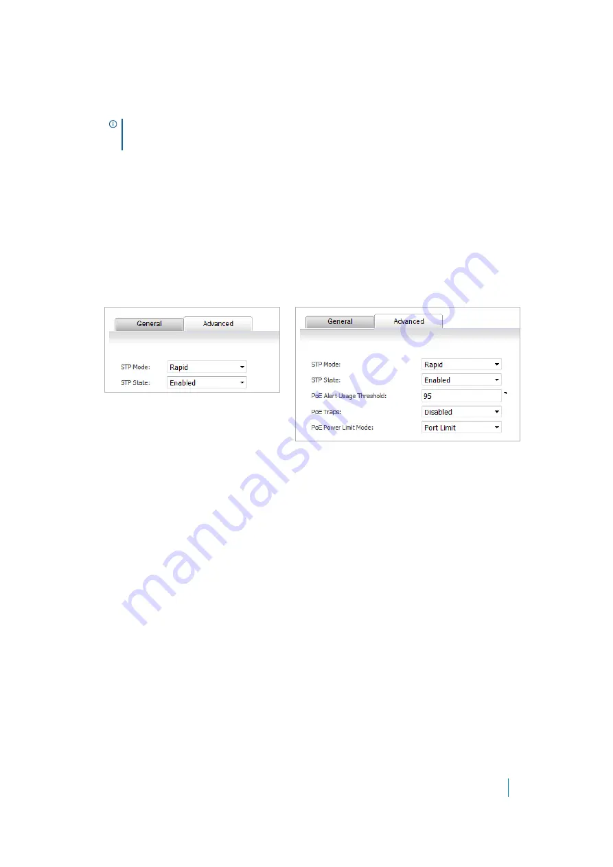
15 Optionally, click the
Advanced
tab. The options on the tab depend on the extended switch you are
adding:
16 From the
STP Mode
drop-down menu, select:
• Classic
• Rapid
(default)
• Multiple
17 From the
STP State
drop-down menu, select:
• Disabled
• Enabled
(default)
18 If you are adding an X1008, X1018, X1026, X1052, or X4012 switch, go to
.
19 In the
PoE Alert Usage Threshold
field, enter the percentage of power consumed before a trap is
generated. The range is 1 to 99, with a default of
95
.
20 From the
PoE Traps
drop-down menu, select whether PoE traps are enabled:
• Disabled
(default)
• Enabled
If this option is enabled when the power usage is above the defined threshold in PoE Alert Usage
Threshold, traps are generated in situations such as status change or port delivering/not delivering
power.
21 From the
PoE Power Limit Mode
drop-down menu, select how the power to the port is determined:
• Port limit
(default) – The power limit of the port depends on the port configuration.
• Class limit
– Each port can get up to the maximum power.
TIP:
For how to configure the
Switch Management
,
Firewall Uplink
, and
Switch Uplink
options,
see the subsection for your topology in
Configuring the X-Series Solution in various topologies
.
X1008, X1018, X1026, X1052, X4012
X1008P, X1018P, X1026P, X1052P


