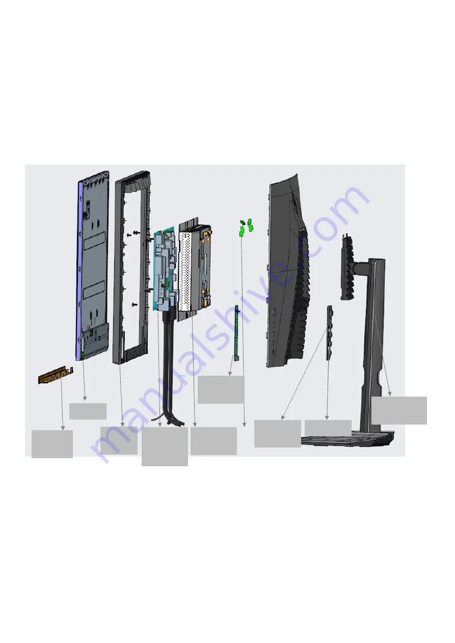
2. Exploded view diagram with list of items
Front trim
Panel
Mid Frame
IF and Power BD
Main bracket
JoystickBD
JoystickKey
OSD key
Stand and Base
Page 1: ...ipment or products It is recommended that service engineers should have repairing knowledge experience as well as appropriate product training per new model before performing the service procedures NOTICE To avoid electrical shocks the products should be connected to an authorized power cord and turn off the master power switch each time before removing the AC power cord To prevent the product awa...
Page 2: ...2 Exploded view diagram with list of items Front trim Panel Mid Frame IF and Power BD Main bracket Joystick BD Joystick Key OSD key Stand and Base ...
Page 3: ... 0 3 B S U 1 n w o D 0 3 B S U AC In Power Board Panel Function Key Board USB3 0 Down4 USB3 0 Down3 USB Board Interface Board Audio Line Out HDMI 2 0 DP 1 4 USB Up Stream HDMI 2 0 USB Down Stream USB Down Stream Power Key Board LED Light Bar ...
Page 4: ...screw size M4x8 Torque 10 11kgfxcm 4 3 2 3 1 2 3 4 1 Lift the rear cover up carefully Disconnect the USB FFC cable joystick key cable and power key cable from the connectors of the interface board and then disconnect the back LED light bar cable from the connector of the power board and then remove the rear cover S4 Use a Philips head screwdriver to remove one screw for unlocking the USB board uni...
Page 5: ...screwdriver to remove 13pcs screws for unlocking the middle bezel with the panel module Use a Philips head screwdriver to remove 2pcs screws for unlocking the middle bezel with the front bezel No 1 13 Screw size M3x5 Torque 3 4kgfxcm No 14 15 Screw size M2x2 7 Torque 1 2kgfxcm Tear off all the adhesive tapes for releasing the panel lamp cable then disconnect the cable away from the connectors of t...
Page 6: ...head screwdriver to remove screws for unlocking power board and interface board and then release the EDP cable from the hook of the bracket 6pcs No 1 screw size M4x8 Torque 6 0 5kgfxcm No 2 7 screw size M3x7 5 Torque 6 0 5kgfxcm S14 Tear off the adhesive tape and then disconnect the EDP cable from the connector of the panel module then put the bracket chassis on a protective cushion S13 3 4 2 1 5 ...
Page 7: ... the hook of the bracket No 1 screw size M4x8 Torque 6 0 5kgfxcm No 2 6 screw size M3x7 5 Torque 6 0 5kgfxcm 3 4 2 1 5 6 S4 Panel preparation Take out 1pcs panel module from the carton remove the protective film by tearing off the tapes then Examine the panel surface according to inspection criteria Turn over the panel to place screen faced down for later assembling Move the bracket chassis module...
Page 8: ...tion of the middle bezel Put the unit into a fixture use a Philips head screwdriver to tighten 1pcs screw for locking the power key board with the middle bezel No 1 Screw size M2x2 4 Torque 0 8 0 2kgfxcm S8 1 Assemble the middle bezel unit with the front bezel and panel module Use a Philips head screwdriver to tighten 2pcs screws for locking the middle bezel with front bezel No 1 2 Screw size M2x2...
Page 9: ...o the joystick key board then locate the joystick key board to the specific position of the rear cover then use a Philips head screwdriver to tighten 4pcs screws for locking the joystick key board with the rear cover Tear off the tape papers on the back of the key cable and then fix the key cable with tapes of the cable No 1 4 screw size M2x0 2 Torque 0 8 0 2kgfxcm S16 S15 reflector S13 1 6 5 4 2 ...
Page 10: ...for European region Stick an energy label on top right bezel of the monitor for Australia and New Zealand S20 S21 Use a Philips head screwdriver to tighten 4pcs screws for locking the rear cover with the assembled unit Paste 2pcs labels on the specific positions No 1 4 screw size M4x10 Torque 9 0 5kgfxcm S19 Move the assembled rear cover close to the panel unit then connect light bar cable to the ...
Page 11: ...wer LED remains white Also depending upon the selected input one of the dialogs shown below will continuously scroll through the screen S2721DGF The display will go into Power Save Mode in 4 minutes www dell com support S2721DGF No DP Cable Dell 27 Gaming Monitor or S2721DGF The display will go into Power Save Mode in 4 minutes www dell com support S2721DGF No HDMI 1 Cable Dell 27 Gaming Monitor 1...
Page 12: ... control highlight the Diagnostics option and press the joystick button to start the diagnostics A gray screen is displayed 4 Observe if the screen has any defects or abnormalities 5 Toggle the joystick once again until a red screen is displayed 6 Observe if the screen has any defects or abnormalities 7 Repeat steps 5 and 6 until the screen displays green blue black and white colors Note any abnor...
Page 13: ...r bent or broken pins in the video cable connector Run the built in diagnostics Ensure that the correct input source is selected in the Input Source menu Missing Pixels LCD screen has spots Cycle power on off Pixel that is permanently off is a natural defect that can occur in LCD technology For more information on Dell Monitor Quality and Pixel Policy see Dell Support site at www dell com pixelgui...
Page 14: ...ail choose the resolution 2560 x 1440 from the Display Properties to force the proper HDR signaling Missing Color Picture missing color Perform monitor self test Ensure that the video cable connecting the monitor to the computer is connected properly and is secure Check for bent or broken pins in the video cable connector Wrong Color Picture color not good Change the settings of the Preset Modes i...
Page 15: ... power saving mode by moving the mouse or pressing any key on the keyboard Check whether the signal cable is plugged in properly Connect the signal cable again if necessary Reset the computer or video player The picture does not fill the entire screen The picture cannot fill the height or width of the screen Due to different video formats aspect ratio of DVDs the monitor may display in full screen...
Page 16: ... Check that your computer is USB 3 0 capable Some computers have USB 3 0 USB 2 0 and USB 1 1 ports Ensure that the correct USB port is used Reconnect the upstream cable to your computer Reconnect the USB peripherals downstream connector Reboot the computer Wireless USB peripherals stop working when a USB 3 0 device is plugged in Wireless USB peripherals responding slowly or only working as the dis...