4.
Rotate the power supply up and out of the way of the system board (see
Figure 20
).
5.
Disconnect the power supply connectors from the POWER_1 and POWER_2 connectors on the system board.
6.
Carefully fold the DC power supply cables you have disconnected and place them outside the chassis.
7.
With the power supply in its rotated position up and away from the system board and chassis, lift up on the front end of the power supply, and
then move that end of the power supply out, away from the chassis (see
Figure 21
).
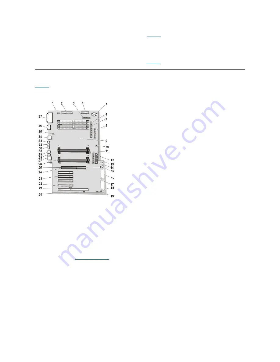
System Board Components
Figure 22
shows the system board and the location of all its sockets and connectors.
Figure 22. System Board Components
1
CD-ROM drive audio connector
2
Main power 1 connector (desktop chassis)
3
Diskette connector
4
Main power 2 connector (desktop chassis)
5
Battery
6
RIMM (memory) sockets
7
SCSI narrow connector
8
Secondary EIDE connector
9
Suspend-To-RAM LED
10
Jumper block (see "
System Board Jumpers
")
11
System board screw
12
LVD SCSI connector
13
Primary EIDE connector
14
Standby power LED
15
Control panel connector
16
MT power 2 connector (mini tower chassis)
17
MT power 1 connector (mini tower chassis)
18
Modem (TAPI) connector
19
Card-cage fan power connector
20
Auxiliary sound input connector
21
PCI/RAID expansion card connector


