background image

Steps

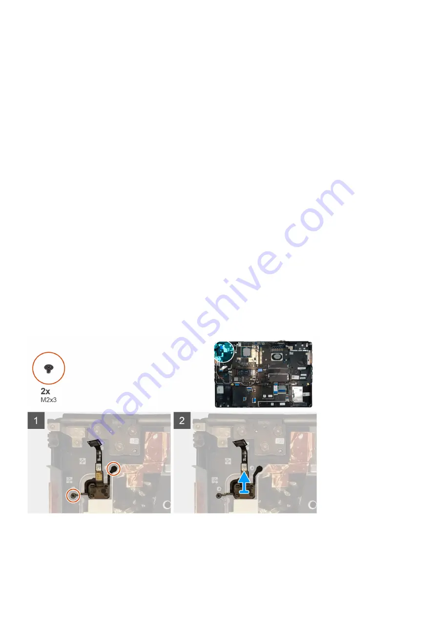
1. Place the power button into its slot on the computer.
2. Replace the two (M2x3) screws to secure the power button in place.

Next steps

1. Install the 

power button board

.

2. Install the 

heat-sink assembly

.

3. Install the 

battery

.

4. Install the 

base cover

.

5. Install the 

SD card

.

6. Follow the procedure in 

after working inside your computer

.

Aan/uit-knopeenheid met vingerafdruklezer

Removing the power button assembly with fingerprint
reader

Prerequisites

1. Follow the procedure in 

before working inside your computer

.

2. Remove the 

SD card

.

3. Remove the 

base cover

.

4. Remove the 

battery

.

5. Remove the 

heat-sink assembly

.

6. Remove the 

power button board assembly with fingerprint reader

.

About this task

The figure indicates the location of the power button and provides a visual representation of the removal procedure.

Steps

1. Remove the two (M2x3) screws that secure the power button assembly with fingerprint reader in its slot on the computer.
2. Remove the power button assembly with fingerprint reader from the computer.

Demonteren en hermonteren

59

Summary of Contents for P44E

Page 1: ...Precision 7750 Service Manual Regulatory Model P44E Regulatory Type P44E001 May 2020 Rev A00 ...

Page 2: ...otentieel gegevensverlies aan en vertellen u hoe het probleem kan worden vermeden GEVAAR LET OP duidt het risico van schade aan eigendommen lichamelijk letsel of overlijden aan 2020 Dell Inc of haar dochterondernemingen Alle rechten voorbehouden Dell EMC en andere handelsmerken zijn handelsmerken van Dell Inc of zijn dochterondernemingen Andere handelsmerken zijn mogelijk handelsmerken van hun res...

Page 3: ...rt installeren 17 SSD deur 17 Removing SSD door 17 Installing SSD door 18 Secundaire M 2 Solid State schijf 19 Removing the secondary M 2 Solid state drive 19 Installing the secondary M 2 SSD module 20 Onderplaat 21 Removing the base cover 21 Installing the base cover 24 Batterij 26 Voorzorgsmaatregelen voor de lithium ionbatterij 26 Removing the battery 26 Installing the battery 27 Solid state sc...

Page 4: ... vingerafdruklezer 47 Removing the power button assembly with fingerprint reader 47 Installing the power button assembly with fingerprint reader 48 Binnenframe 49 Removing the inner frame 49 Installing the inner frame 50 Smartcardhouder 51 Removing the smart card reader 51 Installing the smart card reader 52 Touchpadknop 53 Removing the Touchpad buttons 53 Installing the Touchpad buttons 54 SD kaa...

Page 5: ...emoving the display hinge 87 Installing the display hinge non touch 88 Camera 90 Removing the camera non touch 90 Installing the camera 91 P sensorkaart 92 De P sensorkaart verwijderen 92 De P sensorkaart plaatsen 93 Beeldschermkabel 93 Removing the display cable 93 Installing the display cable 95 Display back cover 96 Replacing the display cable 96 4 Problemen oplossen 98 Dell SupportAssist Pre B...

Page 6: ...ische team voor service en support Schade als gevolg van onderhoudswerkzaamheden die niet door Dell zijn goedgekeurd valt niet onder de garantie Lees de veiligheidsinstructies die bij het product zijn geleverd en leef deze na WAARSCHUWING Voorkom elektrostatische ontlading door uzelf te aarden met een aardingspolsbandje of door regelmatig zowel een ongeverfd metalen oppervlak als een connector aan...

Page 7: ...nd Dell producten met stand bystand moeten worden losgekoppeld voordat u de behuizing opent Systemen die zijn uitgerust met de stand bystand worden in wezen gevoed wanneer deze uit staan Door de interne voeding kan het systeem op afstand worden ingeschakeld Wake on LAN en onderbroken in een slaapstand en heeft andere geavanceerde functies voor energiebeheer Door ontkoppeling en het ingedrukt houde...

Page 8: ...laatsen ESD gevoelige items zijn veilig in uw hand op de ESD mat in het systeem of in een zak Polsband en aardingssnoer De polsband en het aardingssnoer kunnen ofwel direct tussen uw pols en blank metaal op de hardware worden bevestigd als de ESD mat niet vereist is of worden verbonden met de antistatische mat om hardware te beschermen die tijdelijk op de mat is geplaatst De fysieke verbinding van...

Page 9: ...de antistatische mat te allen tijde te gebruiken wanneer service wordt verleend voor Dell producten Daarnaast is het van essentieel belang dat technici de gevoelige onderdelen apart houden van alle isolatoronderdelen wanneer service wordt verleend en dat ze antistatische tassen gebruiken voor het transport van gevoelige onderdelen Nadat u aan de computer heeft gewerkt Over deze taak Nadat u de ond...

Page 10: ...d bekend als de interfacestandaard in de wereld van de personal computers met ongeveer 6 miljard verkochte apparaten Toch wordt de behoefte aan meer snelheid steeds groter door de vraag naar snellere hardware en meer bandbreedte USB 3 0 USB 3 1 Gen 1 voldoet met een theoretisch 10 maal hogere snelheid dan zijn voorganger eindelijk aan de vraag van de consument Kort samengevat heeft USB 3 2 Gen 1 d...

Page 11: ...ebruikelijk voor apparaten die voorheen buiten het USB territorium vielen zoals externe RAID storagesystemen Hieronder staan enkele beschikbare SuperSpeed USB 3 0 USB 3 1 Gen 1 producten Harde schijven met USB 3 0 USB 3 2 Gen 1 voor externe desktop Draagbare USB 3 2 Gen 1 harde schijven Docks en adapters voor schijven met USB 3 2 Gen 1 Flashdrives en lezers met USB 3 2 Gen 1 Solid State schijven m...

Page 12: ...r zo snel is als een eerste generatie Thunderbolt connector USB Type C is niet hetzelfde als USB 3 2 USB Type C is slechts een aansluitingsvorm en de onderliggende technologie kan gewoon USB 2 of USB 3 0 zijn De Android tablet N1 van Nokia bijvoorbeeld maakt gebruik van een USB Type C aansluiting maar aan de binnenkant is alles USB 2 0 zelfs geen USB 3 0 Deze technologieën zijn echter wel nauw ger...

Page 13: ...erlijke Ethernet kabel Audio Return kanaal hiermee kan een op HDMI aangesloten tv met een geïntegreerde tuner audiodata upstream verzenden naar een surround audiosysteem waardoor een afzonderlijke audiokabel niet meer nodig is 3D definieert ingangs uitgangsprotocollen voor grote 3D video indelingen wat mogelijkheden biedt voor echte 3D games en 3D home cinema toepassingen Type inhoud realtime sign...

Page 14: ...rdiepte Maximaal 10 bits kleur Support van grafische kaart Video API voor besturingssystemen DirectX 12 0 OpenGL 4 6 DisplayPort 1 4 DirectX 12 1 Ondersteunde resoluties en max vernieuwingsfrequenties Hz Max digitaal enkele DisplayPort 1 4 7680 x 4320 8k op 30 Hz mDP Type C naar DP Max digitaal dubbele DisplayPort 1 4 7680 x 4320 8k op 60 Hz mDP Type C naar DP Nummers van beeldschermondersteuning ...

Page 15: ...ock 14000 MHz Estimated Maximum Power 100 W Display Support eDP mDP HDMI Type C Maximum Color Depth Up to 10 bit color Operating Systems Graphics Video API Support DirectX 12 0 OpenGL 4 6 DisplayPort 1 4 DirectX 12 1 Supported Resolutions and Max Refresh Rates Hz Max Digital Single DisplayPort 1 4 7680 x 4320 8k 30 Hz mDP Type c to DP Max Digital Dual DisplayPort 1 4 7680 x 4320 8k 60 Hz mDP Type ...

Page 16: ...ms Graphics Video API Support DirectX 12 0 OpenGL 4 6 DisplayPort 1 4 DirectX 12 1 Supported Resolutions and Max Refresh Rates Hz Max Digital Single DisplayPort 1 4 7680 x 4320 8k 30 Hz mDP Type C to DP Max Digital Dual DisplayPort 1 4 7680 x 4320 8k 60 Hz mDP Type C to DP Numbers of Display Support Up to 4 displays 16 Technologie en onderdelen ...

Page 17: ...derdeel te verwijderen alvorens de installatieprocedure uit te voeren Over deze taak De afbeelding geeft de locatie van de onderplaat aan en biedt een visuele weergave van de installatieprocedure Afbeeldingen die tijdens de volgende revisiecyclus moeten worden geüpload Stappen Schuif de SD kaart in de sleuf in de computer totdat de kaart op zijn plaats klikt Vervolgstappen 1 Volg de procedure in N...

Page 18: ...he base cover Installing SSD door Prerequisites If you are replacing a component remove the existing component before performing the installation procedure About this task The figure indicates the location of the SSD door and provides a visual representation of the installation procedure 18 Demonteren en hermonteren ...

Page 19: ...M 2 Solid State schijf Removing the secondary M 2 Solid state drive Prerequisites NOTE For computers shipped with M 2 2280 or 2230 SSD installed in slot 6 1 Follow the procedure in before working inside your computer 2 Remove the SD card 3 Remove the SSD door About this task The figure indicates the location of the secondary M 2 SSD and provides a visual representation of the removal procedure Dem...

Page 20: ...r M 2 2230 SSD a Remove the M 2 2230 SSD with its holder from the SSD carrier b Remove the M2x2 screw to secure the M 2 2230 SSD to its holder c Remove the SSD from the holder Installing the secondary M 2 SSD module Prerequisites NOTE For computers shipped with M 2 2280 or 2230 SSD installed in slot 6 If you are replacing a component remove the existing component before performing the installation...

Page 21: ...ermal plate to the M 2 SSD 5 Replace the SSD module in its slot on the computer 6 Replace the M2x3 screw to secure the SSD module in place Next steps 1 Install the SSD door 2 Install the SD card 3 Follow the procedure in after working inside your computer Onderplaat Removing the base cover Prerequisites 1 Follow the procedure in before working inside your computer 2 Remove the SD card About this t...

Page 22: ...22 Demonteren en hermonteren ...

Page 23: ...en the base cover starting from bottom edge of the cover NOTE For models shipped without SmartCard reader pry open the base cover from the smart card reader slot Use your fingers to pry open the base cover as the use of plastic scribe or any other sharp objects may damage the base cover Demonteren en hermonteren 23 ...

Page 24: ...r on the system board Installing the base cover Prerequisites If you are replacing a component remove the existing component before performing the installation procedure About this task The figure indicates the location of the base cover and provides a visual representation of the installation procedure 24 Demonteren en hermonteren ...

Page 25: ...Demonteren en hermonteren 25 ...

Page 26: ... het oppervlak van de batterij Buig de batterij niet Gebruik geen gereedschap om te wrikken op of langs de batterij Zorg dat er tijdens het onderhoud van dit product geen schroeven zoekraken of verloren gaan om te voorkomen dat de batterij en andere systeemonderdelen per ongeluk worden doorboord of schade oplopen Als de batterij vast komt te zitten in de computer als gevolg van zwellen moet u niet...

Page 27: ...the battery 3 Remove the battery away from the computer Installing the battery Prerequisites If you are replacing a component remove the existing component before performing the installation procedure About this task The figure indicates the location of the battery and provides a visual representation of the installation procedure Demonteren en hermonteren 27 ...

Page 28: ...ter working inside your computer Solid state schijf Removing the primary M 2 Solid state drive Prerequisites NOTE For computers shipped with M 2 2280 or 2230 SSD installed in slot 3 slot 4 and or slot 5 1 Follow the procedure in before working inside your computer 2 Remove the SD card 3 Remove the base cover About this task The figure indicates the location of the primary M 2 SSD and provides a vi...

Page 29: ...t secures the M 2 SSD to the computer b Remove the M 2 SSD 4 For M 2 2230 SSD a Remove the M2x3 screw that secures the SSD module b Remove the SSD module from the computer c Remove the M2x2 screw that secures the SSD to SSD holder d Remove the SSD from the holder 5 Repeat the above steps to remove the other SSD modules in the computer Demonteren en hermonteren 29 ...

Page 30: ...remove the existing component before performing the installation procedure About this task The figure indicates the location of the primary M 2 SSD and provides a visual representation of the installation procedure Steps 1 For M 2 2280 SSD a Place the M 2 SSD onto its slot on the computer b Replace the M2x3 screw to secure the M 2 SSD to the computer 30 Demonteren en hermonteren ...

Page 31: ...computer Next steps 1 Install the base cover 2 Install the SD card 3 Follow the procedure in after working inside your computer Secundaire geheugenmodule Removing the secondary memory module Prerequisites 1 Follow the procedure in before working inside your computer 2 Remove the SD card 3 Remove the base cover About this task The figure indicates the location of the secondary memory module and pro...

Page 32: ...memory module firmly into the slot and press the memory module until it clicks into place NOTE If you do not hear the click remove the memory module and reinstall it Next steps 1 Install the base cover 2 Install the SD card 3 Follow the procedure in after working inside your computer simkaart Removing the SIM card Prerequisites 1 Follow the procedure in before working inside your computer 2 Remove...

Page 33: ...pening 2 Filp the right edge of the SIM card cover to open it 3 Remove the SIM card from the SIM card slot Installing the SIM card Prerequisites If you are replacing a component remove the existing component before performing the installation procedure About this task The figure indicates the location of the SIM card and provides a visual representation of the installation procedure Demonteren en ...

Page 34: ...2 Install the SD card 3 Follow the procedure in after working inside your computer WLAN kaart Removing the WLAN card Prerequisites 1 Follow the procedure in before working inside your computer 2 Remove the SD card 3 Remove the base cover About this task The figure indicates the location of the WLAN card and provides a visual representation of the removal procedure 34 Demonteren en hermonteren ...

Page 35: ...emove the existing component before performing the installation procedure About this task The figure indicates the location of the WLAN card and provides a visual representation of the installation procedure Steps 1 Insert the WLAN card to the connector on the system board 2 Connect the antenna cables to the WLAN card 3 Align and place the WLAN card bracket above the WLAN card to secure the antenn...

Page 36: ...res the WWAN card bracket to the system board 2 Lift the WWAN card bracket from the WWAN card 3 Disconnect the antenna cables from the connector on the WWAN card 4 Slide and remove the WWAN card from its slot on the system board Installing the WWAN card Prerequisites If you are replacing a component remove the existing component before performing the installation procedure About this task The figu...

Page 37: ...Toetsenbordrooster Removing the keyboard lattice Prerequisites 1 Follow the procedure in before working inside your computer 2 Remove the SD card 3 Remove the base cover About this task The figure indicates the location of the keyboard lattice and provides a visual representation of the removal procedure Steps 1 Using a plastic scribe pry the top edge of the keyboard lattice starting from the rece...

Page 38: ...teps 1 Align the keyboard lattice to its position on the keyboard 2 Press the edges on the keyboard lattice until it clicks into place Next steps 1 Install the base cover 2 Install the SD card 3 Follow the procedure in after working inside your computer Toetsenbord Removing the keyboard Prerequisites 1 Follow the procedure in before working inside your computer 2 Remove the SD card 3 Remove the ba...

Page 39: ...rd to the palmrest 4 Pry the bottom edge of the keyboard and then work along the left and the right sides of the keyboard 5 Carefully unroute the keyboard backlight cable and the keyboard cable through the palmrest 6 Remove the keyboard from the system Installing the keyboard Prerequisites If you are replacing a component remove the existing component before performing the installation procedure A...

Page 40: ...em at 90 angle to access the keyboard and the keyboard backlight cables 5 Connect the keyboard backlight cable and the keyboard cable to the connectors on the system board NOTE Ensure that you fold the keyboard data cable in perfect alignment Next steps 1 Install the keyboard lattice 2 Install the battery 3 Install the base cover 4 Install the SD card 5 Follow the procedure in after working inside...

Page 41: ...he SD card 3 Remove the base cover 4 Remove the battery 5 Remove the keyboard lattice 6 Remove the keyboard About this task The figure indicates the location of the primary memory module and provides a visual representation of the removal procedure Steps 1 Remove the M2x3 screw that secures the memory shield in place Demonteren en hermonteren 41 ...

Page 42: ... component remove the existing component before performing the installation procedure About this task The figure indicates the location of the primary memory module and provides a visual representation of the installation procedure Steps 1 Align the notch on the memory module with the tab on the memory module slot 2 Slide the memory module firmly into the slot at an angle and press the memory modu...

Page 43: ...1 Follow the procedure in before working inside your computer 2 Remove the SD card 3 Remove the base cover 4 Remove the battery About this task The figure indicates the location of the heat sink assembly and provides a visual representation of the removal procedure Steps 1 Peel the power adapter cable from the heat sink assembly 2 Disconnect the two fan cables from the connectors on the system boa...

Page 44: ...Align and insert the heat sink assembly into its slot on the computer 2 Tighten the eight captive screws to secure the heat sink assembly to the system board NOTE Tighten the captive screws in the order stamped onto the heat sink next to the screws 1 2 3 4 5 6 7 8 3 Connect the two fan cables to the connector on the system board 4 Adhere the power adapter cable on the heat sink assembly Next steps...

Page 45: ... Remove the M2x3 screw that secures power adapter cable bracket 2 Remove the power adapter cable bracket from the computer 3 Lift the power adapter port from its slot on the palmrest 4 Unroute and remove the power adapter cable from the computer Installing the power adapter port Prerequisites If you are replacing a component remove the existing component before performing the installation procedur...

Page 46: ...e base cover 4 Install the SD card 5 Follow the procedure in after working inside your computer Aan uitknopkaart Removing the power button board Prerequisites 1 Follow the procedure in before working inside your computer 2 Remove the SD card 3 Remove the base cover 4 Remove the battery 5 Remove the heat sink assembly About this task The figure indicates the location of the power button board and p...

Page 47: ...ble into its slot on the computer 3 Replace the two M2x3 screws to secure the power button board 4 Adhere the power button board cable to the palmrest 5 Connect the power button board cable to the connector on the system board Next steps 1 Install the heat sink assembly 2 Install the battery 3 Install the base cover 4 Install the SD card 5 Follow the procedure in after working inside your computer...

Page 48: ...ard cable from the palmrest 6 Remove the two M2x3 screws that secure the power button board to the computer 7 Remove the power button board with the power button board cable from the computer 8 Disconnect the power button board cable from the power button board Installing the power button assembly with fingerprint reader Prerequisites If you are replacing a component remove the existing component ...

Page 49: ... the power button daughter board 8 Replace the M2 5x2 5 screw to secure the power button assembly with fingerprint reader cable bracket in place Next steps 1 Install the heat sink assembly 2 Install the battery 3 Install the base cover 4 Install the SD card 5 Follow the procedure in after working inside your computer Binnenframe Removing the inner frame Prerequisites 1 Follow the procedure in befo...

Page 50: ...sis 4 Remove the inner frame from the computer while carefully unthreading the keyboard cable and keyboard backlight cable through the opening on the inner frame Installing the inner frame Prerequisites If you are replacing a component remove the existing component before performing the installation procedure About this task The figure indicates the location of the inner frame and provides a visua...

Page 51: ...he WLAN card 2 Install the WWAN card 3 Install the primary M 2 SSD 4 Install the battery 5 Install the base cover 6 Install the SD card 7 Follow the procedure in after working inside your computer Smartcardhouder Removing the smart card reader Prerequisites 1 Follow the procedure in before working inside your computer 2 Remove the SD card 3 Remove the base cover 4 Remove the battery 5 Remove the p...

Page 52: ... smart card reader cable from the touchpad 4 Remove the two M2x2 5 screws that secure the smart card reader to the computer 5 Remove the smart card reader from the computer Installing the smart card reader Prerequisites If you are replacing a component remove the existing component before performing the installation procedure About this task The figure indicates the location of the smart card read...

Page 53: ...xt steps 1 Install the WLAN card 2 Install the WWAN card 3 Install the primary M 2 SSD 4 Install the inner frame 5 Install the battery 6 Install the base cover 7 Install the SD card 8 Follow the procedure in after working inside your computer Touchpadknop Removing the Touchpad buttons Prerequisites 1 Follow the procedure in before working inside your computer 2 Remove the SD card 3 Remove the base...

Page 54: ...nect the touchpad buttons cable from the connector on the touchpad 3 Remove the two M2x2 5 screws that secure the touchpad buttons to the palmrest 4 Remove the touchpad buttons from the palmrest Installing the Touchpad buttons Prerequisites If you are replacing a component remove the existing component before performing the installation procedure About this task The figure indicates the location o...

Page 55: ...he touchpad Next steps 1 Install the inner frame 2 Install the WLAN card 3 Install the WWAN card 4 Install the primary M 2 SSD 5 Install the battery 6 Install the base cover 7 Install the SD card 8 Follow the procedure in after working inside your computer SD kaartlezer Removing SD card reader Prerequisites 1 Follow the procedure in before working inside your computer 2 Remove the SD card 3 Remove...

Page 56: ...ottom side of the computer 3 Remove the M2 5x2 5 screw that secures the SD card reader in place 4 Slide and remove the SD card reader with its cable out of the computer Installing SD card reader Prerequisites If you are replacing a component remove the existing component before performing the installation procedure About this task The figure indicates the location of the SD card reader and provide...

Page 57: ... 4 Install the primary M 2 SSD 5 Install the inner frame 6 Install the battery 7 Install the base cover 8 Install the SD card 9 Follow the procedure in after working inside your computer Aan uit knop Removing the power button Prerequisites 1 Follow the procedure in before working inside your computer 2 Remove the SD card 3 Remove the base cover 4 Remove the battery 5 Remove the heat sink assembly ...

Page 58: ...e computer Installing the power button Prerequisites If you are replacing a component remove the existing component before performing the installation procedure About this task The figure indicates the location of the power button and provides a visual representation of the installation procedure 58 Demonteren en hermonteren ...

Page 59: ...ingerprint reader Prerequisites 1 Follow the procedure in before working inside your computer 2 Remove the SD card 3 Remove the base cover 4 Remove the battery 5 Remove the heat sink assembly 6 Remove the power button board assembly with fingerprint reader About this task The figure indicates the location of the power button and provides a visual representation of the removal procedure Steps 1 Rem...

Page 60: ...into its slot on the computer 2 Replace the two M2x3 screws to secure the power button assembly with fingerprint reader in place Next steps 1 Install the power button board assembly with fingerprint reader 2 Install the heat sink assembly 3 Install the battery 4 Install the base cover 5 Install the SD card 6 Follow the procedure in after working inside your computer GPU voedingskabel Removing the ...

Page 61: ...y slide the GPU power cable connector outwards to disconnect the GPU power cable from the GPU card 3 Repeat the above steps to disconnect the GPU power cable from the system board 4 Peel the GPU power cable from the computer Installing the GPU power cable Prerequisites If you are replacing a component remove the existing component before performing the installation procedure About this task The fi...

Page 62: ... the keyboard lattice 3 Install the battery 4 Install the base cover 5 Install the SD card 6 Follow the procedure in after working inside your computer Moederbord Removing the system board Prerequisites 1 Follow the procedure in before working inside your computer 2 Remove the SD card 3 Remove the SSD door 4 Remove the secondary M 2 SSD 5 Remove the base cover 6 Remove the battery 7 Remove the pri...

Page 63: ...heat sink assembly 16 Remove the inner frame About this task The figure indicates the location of the system board and provides a visual representation of the removal procedure Images to be uploaded in the next review cycle NOTE For discrete models shipped with GPU card Demonteren en hermonteren 63 ...

Page 64: ...ra power adapter cable touchpad cable USH daughter board cable for models shipped with a USH daughter board and power button board cable from the system board 5 Remove the M2x3 screw that secures the Darwin cable bracket in place 6 Remove the Darwin cable bracket 7 Disconnect the Darwin cables from the connectors on the system board 8 Remove the six M2x3 screws that secure the three beam connector...

Page 65: ...ystem board 14 Remove the four M2x5 screws that secure the system board to the computer 15 Pry the coin cell battery located under the system board from the palmrest while lifting the system board 16 Remove the system board from the computer Installing the system board Prerequisites If you are replacing a component remove the existing component before performing the installation procedure About th...

Page 66: ...66 Demonteren en hermonteren ...

Page 67: ...e connector 8 Replace the M2x3 screw to secure the Darwin cable bracket to the system board 9 Connect the beam connectors on the system board NOTE For UMA models replace the two M2x3 screws to secure the single beam connector in place on the bottom side of the system For discrete models shipped with a 128 MB vram GPU card replace the four M2x3 screws to secure the two beam connector in place on th...

Page 68: ...wijder de batterij 7 Verwijder de primaire M 2 SSD 8 Verwijder de simkaart 9 Verwijder het secundaire geheugen 10 Verwijder de WWAN kaart 11 Verwijder de WLAN kaart 12 Verwijder het toetsenbordrooster 13 Verwijder het toetsenbord 14 Verwijder de GPU voedingskabel 15 Verwijder het primaire geheugen 16 Verwijder de warmteafleiderassemblage 17 Verwijder het binnenframe 18 Verwijder de systeemkaart Ov...

Page 69: ...aats de GPU voedingskabel 6 Het toetsenbord plaatsen 7 Plaats het toetsenbordrooster 8 Plaats de WLAN kaart 9 Plaats de WWAN kaart 10 Plaats het secundaire geheugen 11 Plaats de simkaart 12 Plaats de primaire M 2 SSD 13 Installeer de batterij 14 Installeer de onderplaat 15 Plaats de secundaire M 2 SSD 16 Plaats de SSD deur 17 Plaats de SD kaart 18 Volg de procedure in Nadat u in de computer hebt g...

Page 70: ...ext review cycle Steps 1 Peel the pieces of adhesive tape that secures the speaker cable to the palmrest 2 Pry the speaker module from its slot on the top edge of the palmrest 3 Remove the speaker module from the computer Installing the speaker Prerequisites If you are replacing a component remove the existing component before performing the installation procedure About this task The figure indica...

Page 71: ...e inner frame 5 Install the heat sink assembly 6 Install the primary memory 7 Install the keyboard 8 Install the keyboard lattice 9 Install the WLAN card 10 Install the WWAN card 11 Install the secondary memory 12 Install the SIM card 13 Install the primary M 2 SSD 14 Install the battery 15 Install the base cover 16 Install the secondary M 2 SSD 17 Install the SSD door 18 Install the SD card 19 Fo...

Page 72: ...AN card 11 Remove the WLAN card 12 Remove the keyboard lattice 13 Remove the keyboard 14 Remove the primary memory 15 Remove the heat sink assembly 16 Remove the inner frame 17 Remove the GPU power cable 18 Remove the GPU card 19 Remove the system board About this task The figure indicates the location of the speaker and provides a visual representation of the removal procedure Images to be upload...

Page 73: ...almrest NOTE Ensure that the middle cap is secured in place by the two pegs on the palmrest 2 Replace the four M2x3 screws to secure the middle cap in place Next steps 1 Install the system board 2 Install the GPU card 3 Install the GPU power cable 4 Install the inner frame 5 Install the heat sink assembly 6 Install the primary memory 7 Install the keyboard 8 Install the keyboard lattice 9 Install ...

Page 74: ... card 3 Remove the SSD door 4 Remove the secondary M 2 SSD 5 Remove the base cover 6 Remove the battery 7 Remove the primary M 2 SSD 8 Remove the SIM card 9 Remove the secondary memory 10 Remove the WWAN card 11 Remove the WLAN card 12 Remove the keyboard lattice 13 Remove the keyboard 14 Remove the primary memory 15 Remove the heat sink assembly About this task The figure indicates the location o...

Page 75: ...Demonteren en hermonteren 75 ...

Page 76: ...ures the Darwin bracket 5 Peel and remove the WWAN cables and Darwin cables from the palmrest 6 Remove the eight M2 5x2 5 screws that secures the hinges to the palmrest 7 Remove the display assembly from the palmrest Installing the display assembly Prerequisites If you are replacing a component remove the existing component before performing the installation procedure About this task The figure in...

Page 77: ...Demonteren en hermonteren 77 ...

Page 78: ...cure the display bracket to the palmrest 4 Connect the display cable to the connector on the system board 5 Replace the M2x5 screw to secure the Darwin bracket 6 Adhere the WWAN cables and Darwin cables to the palmrest Next steps 1 Install the heat sink assembly 2 Install the primary memory 3 Install the keyboard 4 Install the keyboard lattice 5 Install the WLAN card 6 Install the WWAN card 7 Inst...

Page 79: ...keyboard lattice 13 Remove the keyboard 14 Remove the primary memory 15 Remove the power adapter port 16 Remove the power button board 17 Remove the smart card reader 18 Remove the touchpad buttons 19 Remove the SD card reader 20 Remove the power button or power button assembly with fingerprint reader 21 Remove the heat sink assembly 22 Remove the inner frame 23 Remove the GPU power cable 24 Remov...

Page 80: ...existing component before performing the installation procedure About this task The figure indicates the palmrest and before performing the pre installation parts procedures for any palmrest installation procedure Next steps 1 Install the display assembly 80 Demonteren en hermonteren ...

Page 81: ...attery 24 Install the base cover 25 Install the secondary M 2 SSD 26 Install the SSD door 27 Install the SD card 28 Follow the procedure in after working inside your computer Montagekader van het beeldscherm Removing the display bezel non touch Prerequisites 1 Follow the procedure in before working inside your computer 2 Remove the SD card 3 Remove the SSD door 4 Remove the secondary M 2 SSD 5 Rem...
Page 82: ...around the sides and top edge of the display bezel NOTE While prying the display bezel make sure to pry along the outside edge of the display bezel using your hands using a screw driver or other sharp objects may damage the display cover 3 Remove the display bezel from the display assembly Installing the display bezel non touch Prerequisites If you are replacing a component remove the existing com...

Page 83: ...ll the GPU card 6 Install the GPU power cable 7 Install the inner frame 8 Install the heat sink assembly 9 Install the primary memory 10 Install the keyboard 11 Install the keyboard lattice 12 Install the WLAN card 13 Install the WWAN card 14 Install the secondary memory 15 Install the SIM card 16 Install the primary M 2 SSD 17 Install the battery 18 Install the base cover 19 Install the secondary...

Page 84: ... 10 Remove the WWAN card 11 Remove the WLAN card 12 Remove the keyboard lattice 13 Remove the keyboard 14 Remove the primary memory 15 Remove the heat sink assembly 16 Remove the inner frame 17 Remove the GPU power cable 18 Remove the GPU card 19 Remove the system board 20 Remove the display assembly 21 Remove the speaker 22 Remove the middle cap 23 Remove the display assembly 24 Remove the displa...

Page 85: ... the adhesive tapes that secures the display cable 5 Peel the adhesive rubber strip covering the display cable 6 Unlock the display cable connector and then disconnect the display cable from the back of the display panel 7 Remove the display panel form the display assembly 8 Remove the display panel NOTE The support brackets attached to the display panel are defined as a single service assembly pa...

Page 86: ... a visual representation of the installation procedure Steps 1 Connect the display cable to the connector on the back of the display panel and lock the display cable connector 2 Adhere the adhesive rubber strip to cover the display cable 3 Adhere the transparent tape and conductive tape above the rubber strip to cover the display cable 4 Align the display panel with the tabs on the display assembl...

Page 87: ...nstall the base cover 21 Install the secondary M 2 SSD 22 Install the SSD door 23 Install the SD card 24 Follow the procedure in after working inside your computer Beeldschermscharnieren Removing the display hinge Prerequisites 1 Follow the procedure in before working inside your computer 2 Remove the SD card 3 Remove the SSD door 4 Remove the secondary M 2 SSD 5 Remove the base cover 6 Remove the...

Page 88: ... Steps 1 Remove the eight M2 5x2 5 screws that secures the display hinges to the display assembly 2 Remove the display hinges Installing the display hinge non touch Prerequisites If you are replacing a component remove the existing component before performing the installation procedure About this task The figure indicates the display hinge and provides a visual representation of the installation p...

Page 89: ...Install the GPU power cable 8 Install the inner frame 9 Install the heat sink assembly 10 Install the primary memory 11 Install the keyboard 12 Install the keyboard lattice 13 Install the WLAN card 14 Install the WWAN card 15 Install the secondary memory 16 Install the SIM card 17 Install the primary M 2 SSD 18 Install the battery 19 Install the base cover 20 Install the secondary M 2 SSD 21 Insta...

Page 90: ... the WLAN card 12 Remove the keyboard lattice 13 Remove the keyboard 14 Remove the primary memory 15 Remove the heat sink assembly 16 Remove the inner frame 17 Remove the GPU power cable 18 Remove the GPU card 19 Remove the system board 20 Remove the display assembly 21 Remove the speaker 22 Remove the display bezel 23 Remove the display panel About this task The figure indicates the location of t...

Page 91: ...a and provides a visual representation of the installation procedure Steps 1 Place the camera module in its slot on the display back cover 2 Place the camera shutter cap on the top edge of the camera shutter 3 Connect the display cable to the camera module 4 Adhere the adhesive tape to cover the camera module Next steps 1 Install the display panel 2 Install the display bezel 3 Install the speaker ...

Page 92: ...LAN kaart 12 Verwijder het toetsenbordrooster 13 Verwijder het toetsenbord 14 Verwijder het primaire geheugen 15 Verwijder de warmteafleiderassemblage 16 Verwijder het binnenframe 17 Verwijder de GPU voedingskabel 18 Verwijder de GPU kaart 19 Verwijder de systeemkaart 20 Verwijder de beeldschermassemblage 21 Verwijder de luidspreker 22 Verwijder het montagekader van het beeldscherm 23 Verwijder he...

Page 93: ...eenheid 5 Installeer de systeemkaart 6 Plaats de GPU kaart 7 Plaats de GPU voedingskabel 8 Plaats het binnenframe 9 Plaats de koelplaat 10 Plaats het primaire geheugen 11 Het toetsenbord plaatsen 12 Plaats het toetsenbordrooster 13 Plaats de WLAN kaart 14 Plaats de WWAN kaart 15 Plaats het secundaire geheugen 16 Plaats de simkaart 17 Plaats de primaire M 2 SSD 18 Installeer de batterij 19 Installe...

Page 94: ...mbly 21 Remove the speaker 22 Remove the display bezel 23 Remove the display panel 24 Remove the P sensor board About this task The figure indicates the location of the display cable and provides a visual representation of the removal procedure Images to be uploaded in the next review cycle Steps 1 Peel the adhesive tape covering the camera module 2 Disconnect the display cable from the camera mod...

Page 95: ...es a visual representation of the installation procedure Steps 1 Route and adhere the display cable on the display back cover 2 Connect the display cable to the connector on the camera module 3 Adhere the adhesive tape to cover the camera module Next steps 1 Install the P sensor board 2 Install the display panel 3 Install the display bezel 4 Install the speaker 5 Install the display assembly 6 Ins...

Page 96: ...d 3 Remove the SSD door 4 Remove the secondary M 2 SSD 5 Remove the base cover 6 Remove the battery 7 Remove the primary M 2 SSD 8 Remove the SIM card 9 Remove the secondary memory 10 Remove the WWAN card 11 Remove the WLAN card 12 Remove the keyboard lattice 13 Remove the keyboard 14 Remove the primary memory 15 Remove the heat sink assembly 16 Remove the inner frame 17 Remove the GPU power cable...

Page 97: ... card 11 Install the GPU power cable 12 Install the inner frame 13 Install the heat sink assembly 14 Install the primary memory 15 Install the keyboard 16 Install the keyboard lattice 17 Install the WLAN card 18 Install the WWAN card 19 Install the secondary memory 20 Install the SIM card 21 Install the primary M 2 SSD 22 Install the battery 23 Install the base cover 24 Install the secondary M 2 S...

Page 98: ...ten is gebruikersinteractie vereist Zorg er voor dat u altijd aanwezig bent bij de computerterminal wanneer er diagnostische testen worden uitgevoerd Zie voor meer informatie Hardwareproblemen oplossen met ingebouwde en online diagnostische gegevens SupportAssist ePSA ePSA of PSA foutcodes De PerformanceAssist Pre Boot System prestatiecontrole uitvoeren Stappen 1 Schakel de computer in 2 Druk tijd...

Page 99: ...r de systeemkaart naar behoren functioneert Geïntegreerde zelftest van de stroomrail van het beeldscherm L BIST Over deze taak Vervolgstappen L BIST LCD Power Rail Test is een verbetering van de enkele LED foutcodediagnostiek en wordt automatisch gestart tijdens POST L BIST isoleert wanneer de LCD stroom krijgt van de systeemkaart L BIST controleert of de systeemkaart stroom levert aan de LCD door...

Page 100: ...s light Indicates the power and battery charge status Solid white Power adapter is connected and the battery has more than 5 percent charge Amber Computer is running on battery and the battery has less than 5 percent charge Off Power adapter is connected and the battery is fully charged Computer is running on battery and the battery has more than 5 percent charge Computer is in sleep state hiberna...

Page 101: ... module 2 6 Motherboard Chipset Error Flash latest BIOS version If problem persists replace the system board 2 7 LCD failure SBIOS message Flash latest BIOS version If problem persists replace the LCD module 2 8 LCD failure EC detection of power rail failure Replace the system board 3 1 CMOS battery failure Reset the CMOS battery connection If problem persists replace the RTC battery 3 2 PCI of Vi...

Page 102: ...nde procedure bevat de instructies voor het uitvoeren van een Wifi stroomcyclus OPMERKING Sommige ISP s Internet Service Providers bieden een gecombineerde modem router Stappen 1 Zet de computer uit 2 Schakel de modem uit 3 Schakel de draadloze router uit 4 Wacht 30 seconden 5 Schakel de draadloze router in 6 Schakel de modem in 7 Zet de computer aan 102 Problemen oplossen ...

Page 103: ...servicemogelijkheden De beschikbaarheid verschilt per land en product en sommige services zijn mogelijk niet beschikbaar in uw regio Wanneer u met Dell contact wilt opnemen voor vragen over de verkoop technische ondersteuning of de klantenservice Stappen 1 Ga naar Dell com support 2 Selecteer uw ondersteuningscategorie 3 Zoek naar uw land of regio in het vervolgkeuzemenu Kies een land regio ondera...

Reviews: