background image

Back to Removing and Replacing Parts


IEEE 1394 Port 

Dell™ Latitude™ E6410/E6410 ATG Service Manual


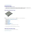
Removing the IEEE 1394 Port 


1.

Follow the procedures in 

Before Working Inside Your Computer

.  

2.

Remove the 

ATG Port Cover

 (applicable on E6410 ATG computer only).  

3.

Remove the 

battery

.  

4.

Remove the 

SIM card

.  

5.

Remove the 

SD card

.  

6.

Remove the 

ExpressCard

.  

7.

Remove the 

Smart card

.  

8.

Remove the 

hinge covers

.  

9.

Remove the 

access panel

.  

10.

Remove the 

optical drive

.  

11.

Remove the 

hard drive

.  

12.

Remove the 

LED cover

.  

13.

Remove the 

keyboard

.  

14.

Remove the 

coin-cell battery

.  

15.

Remove the 

memory

.  

16.

Remove the 

WWAN card

.  

17.

Remove the 

WLAN card

.  

18.

Remove the 

Latitude On™ Flash/CMG module

.  

19.

Remove the 

Fingerprint Reader

.  

20.

Remove the 

Heat Sink and Processor Fan

.  

21.

Remove the 

Display Assembly

.  

22.

Peel back the Ferrite sheet covering the firewire cable. 


23.

Disconnect and unthread the firewire data cable from the system board. 


24.

Remove the screws that secure the IEEE 1394 board to the computer. 


25.

Remove the IEEE 1394 board from the computer. 


Replacing the IEEE 1394 Port 

To replace the IEEE 1394 port, perform the above steps in reverse order. 

Back to Removing and Replacing Parts


WARNING: 

Before working inside your computer, read the safety information that shipped with your computer. For additional safety best 

practices information, see the Regulatory Compliance Homepage at www.dell.com/regulatory_compliance. 

NOTE:

 You may need to install Adobe

® 

Flash

® 

Player from 

Adobe.com

 in order to view the illustrations below. 

Summary of Contents for Latitude E6410

Page 1: ...nd the Windows Vista start button are either trademarks or registered trademarks of Microsoft Corporation in the United States and or other countries Adobe the Adobe logo and Flash are either registered trademarks or trademarks of Adobe Systems Incorporated in the United States and or other countries ATI FirePro is a trademark of Advanced Micro Devices Inc Other trademarks and trade names may be u...

Page 2: ...g tables describe the menu options for the System Setup program Action Keystroke s Exit BIOS Esc or click Exit Apply a setting click Apply Reset defaults click Load Defaults Expand and collapse field Enter General Option Description System Information This section lists the primary hardware features of your computer There are no configurable options in this section l System Information l Memory In...

Page 3: ...stem or hard drive password NOTE Successful password changes take effect immediately NOTE Deleting the admin password automatically deletes the system password as well Default Setting Not Set System Password Allows you to set change or delete the system password When set your computer requests you to enter the system password every time your computer turns on or restarts NOTE Successful password c...

Page 4: ...tically The settings are Disabled Everyday or Weekdays Default setting Disabled USB Wake Support Allows you to enable or disable the ability of USB devices to wake the computer from Standby This feature is only functional when the AC power adapter is connected If the AC power adapter is removed during Standby the BIOS will remove power from all of the USB ports to conserve battery power Default se...

Page 5: ...ion Support Option Description Virtualization Specifies whether a Virtual Machine Monitor VMM can utilize the additional hardware capabilities provided by Intel Virtualization Technology Default setting Enabled VT for Direct I O Specifies whether a Virtual Machine Monitor VMM can utilize the additional hardware capabilities provided by Intel Virtualization Technology for Direct I O Default setting...

Page 6: ...Back to Contents Page ...

Page 7: ...the battery charge gauge for at least 3 seconds If no lights appear the battery is in good condition and more than 80 percent of its original charge capacity remains Each light represents incremental degradation If five lights appear less than 60 percent of the charge capacity remains and you should consider replacing the battery Keyboard Status Lights The green lights located above the keyboard i...

Page 8: ...rrors 1 Reseat the memory 2 If two modules are installed remove one and test Try the other module in the same slot and test Test the other slot with both modules 3 Replace the memory 4 Replace the system board OFF FLASH FLASH Modem error 1 Reseat the modem 2 Replace the modem 3 Replace the system board FLASH FLASH FLASH System board error Replace the system board FLASH FLASH OFF Option ROM error 1...

Page 9: ...ell battery WWAN Card Latitude ON Card CMG Module Heat Sink and Processor Fan Modem Connector Plug LED Cover Display Bezel Display Panel Fingerprint Reader Bluetooth Card System Board Modem Connector SD Card Reader Battery SD Card Smart Card Hard Drive Hinge Covers Memory WLAN Card Processor Fan Processor Modem Keyboard Display Assembly Camera Palm Rest ExpressCard Cage IEEE 1394 Port Power Connec...

Page 10: ...must install memory in pairs for the dual channel mode to work Flash EPROM SPI 32 Mbits PCI bus 32 bits 33 MHz Processor Types Intel Core i5 series Intel Core i7 series L2 cache Intel Core i5 520M 540M Dual Core 3 MB Intel Core i7 620M Dual Core 4 MB External bus frequency 1066 MHz Memory Type DDR3 SDRAM Speed 1066 MHz Connectors two SODIMM connectors Module capacities 1 GB 2 GB 4 GB Minimum memor...

Page 11: ...E6410 with either a PC card or an ExpressCard slot NOTE E6410 ATG supports PC Cards only Secure Digital SD Memory Card Reader Cards supported SD MMC SDHC SDHS MiniSD MicroSD SDIO Contactless Smart Cards Optional Supported Smart Cards and Technologies ISO14443A 106 kbps 212 kbps 424 kbps and 848 kbps ISO14443B 106 kbps 212 kbps 424 kbps and 848 kbps ISO15693 HID iClass FIPS201 NXP Desfire Fingerpri...

Page 12: ...2370 mm x 0 2370 mm Display Option 2 WXGA Anti Glare WXGA Touch feature Maximum resolution 1440 H x 900 V at 262K colors 1280 H x 800 V at 262K colors Typical brightness 300 nits 630 nits Refresh rate 60 Hz 60 Hz Viewing angle Horizontal 40 degrees 40 degrees 55 degrees 55 degrees Vertical 15 degrees 30 degrees 45 degrees 45 degrees Pixel pitch 0 2109 mm x 0 2109 mm 0 2370 mm x 0 2370mm Keyboard N...

Page 13: ...um 1 5 A Input frequency 50 Hz 60 Hz Output power 65 W or 90 W Output current 65 W E6410 with UMA video only 3 34 A continuous 90 W 4 62 A continuous Dimensions Depth 65 W 127 00 mm 4 99 inches 90 W 147 00 mm 5 78 inches Height 65 W 16 00 mm 0 63 inch 90 W 16 00 mm 0 63 inch Width 65 W 66 04 mm 2 60 inches 90 W 70 00 mm 2 75 inches Temperature range Operating 0 C to 35 C 32 F to 95 F Storage 40 C ...

Page 14: ...ation Operating 0 66 Grms 2 Hz 600 Hz Non operating 1 30 Grms 2 Hz 600 Hz NOTE Vibration is measured using a random vibration spectrum that simulates user environment Maximum shock Operating 110 G 2 ms Non operating 160 G 2 ms NOTE Shock is measured with hard drive in head parked position and a 2 ms half sine pulse Altitude Operating 15 20 m to 3048 m 50 ft to 10 000 ft Non operating 15 20 m to 10...

Page 15: ... panel toward the front of the computer 6 Lift and remove the access panel off of the computer Replacing the Access Panel To replace the access panel perform the above steps in reverse order Back to Removing and Replacing Parts WARNING Before working inside your computer read the safety information that shipped with your computer For additional safety best practices information see the Regulatory ...

Page 16: ...cing the ATG Port Cover To replace the ATG port cover perform the above steps in reverse order Back to Removing and Replacing Parts WARNING Before working inside your computer read the safety information that shipped with your computer For additional safety best practices information see the Regulatory Compliance Homepage at www dell com regulatory_compliance NOTE You may need to install Adobe Fla...

Page 17: ...ter and remove it Replacing the Battery To replace the battery perform the above steps in reverse order Back to Removing and Replacing Parts WARNING Before working inside your computer read the safety information that shipped with your computer For additional safety best practices information see the Regulatory Compliance Homepage at www dell com regulatory_compliance NOTE You may need to install ...

Page 18: ...WAN card 17 Remove the WLAN card 18 Remove the Latitude ON Flash CMG module 19 Remove the Fingerprint Reader 20 Remove the Heat Sink and Processor Fan 21 Remove the screw that secures the Bluetooth card to the computer 22 Disconnect the Bluetooth cable from the computer 23 Remove the Bluetooth card from the computer Replacing the Bluetooth Card To replace the Bluetooth card perform the above steps...

Page 19: ...computer 6 Disconnect the data cable to remove the camera from the computer Replacing the Camera To replace the camera perform the above steps in reverse order Back to Removing and Replacing Parts WARNING Before working inside your computer read the safety information that shipped with your computer For additional safety best practices information see the Regulatory Compliance Homepage at www dell...

Page 20: ... Sink and Processor fan 13 Remove the display assembly 14 Remove the palm rest 15 Remove the screws that secures the ExpressCard cage to the computer 16 Lift the ExpressCard cage and slide the ExpressCard cage out of the computer Replacing the ExpressCard Cage To replace the ExpressCard cage perform the above steps in reverse order Back to Removing and Replacing Parts WARNING Before working inside...

Page 21: ...m the system board 6 Lift and remove the coin cell battery out of its socket Replacing the Coin cell Battery To replace the coin cell battery perform the above steps in reverse order Back to Removing and Replacing Parts WARNING Before working inside your computer read the safety information that shipped with your computer For additional safety best practices information see the Regulatory Complian...

Page 22: ...ve screws that secure the display cable to the system board 9 Disconnect and unthread the display data cable from the system board 10 Remove the screws that secure the display assembly to the computer 11 Lift and remove the display assembly from the computer Replacing the Display Assembly To replace the display assembly perform the above steps in reverse order Back to Removing and Replacing Parts ...

Page 23: ...the snaps loosen remove the display bezel from the display assembly Replacing the Display Bezel To replace the display bezel perform the above steps in reverse order Back to Removing and Replacing Parts WARNING Before working inside your computer read the safety information that shipped with your computer For additional safety best practices information see the Regulatory Compliance Homepage at ww...

Page 24: ...m the LCD panel 8 Disconnect the touch screen cable if present 9 Remove the display panel 10 Remove the screws that secure the left display bracket to the display panel 11 Remove the screws that secure the right display bracket to the display panel Replacing the Display Panel To replace the display panel perform the above steps in reverse order Back to Removing and Replacing Parts WARNING Before w...

Page 25: ...to release the card 5 Remove the card out of the computer Replacing the ExpressCard To replace the ExpressCard perform the above steps in reverse order Back to Removing and Replacing Parts WARNING Before working inside your computer read the safety information that shipped with your computer For additional safety best practices information see the Regulatory Compliance Homepage at www dell com reg...

Page 26: ...e screws that secure the processor fan onto the heat sink 7 Remove the processor fan from the computer Replacing the Processor Fan To replace the processor fan perform the above steps in reverse order Back to Removing and Replacing Parts WARNING Before working inside your computer read the safety information that shipped with your computer For additional safety best practices information see the R...

Page 27: ...rint reader 9 Disconnect the fingerprint reader data cable from the system board 10 Peel off the Mylar to release the cable and fingerprint reader from the computer to remove the fingerprint reader Replacing the Fingerprint Reader To replace the fingerprint reader perform the above steps in reverse order Back to Removing and Replacing Parts WARNING Before working inside your computer read the safe...

Page 28: ...ve the screw that secures the hard drive caddy to the hard drive 7 Pull and remove the hard drive caddy away from the hard drive Replacing the Hard Drive To replace the hard drive perform the above steps in reverse order Back to Removing and Replacing Parts WARNING Before working inside your computer read the safety information that shipped with your computer For additional safety best practices i...

Page 29: ... the heat sink 8 Lift the edge of the heat sink that is closest to the center of the computer and then slide the heat sink out of the computer Replacing the Heat Sink and Processor Fan To replace the heat sink and processor fan perform the above steps in reverse order Back to Removing and Replacing Parts WARNING Before working inside your computer read the safety information that shipped with your...

Page 30: ...e the hinge covers toward the back of the computer and remove the hinge cover Replacing the Hinge Covers To replace the hinge covers perform the above steps in reverse order Back to Removing and Replacing Parts WARNING Before working inside your computer read the safety information that shipped with your computer For additional safety best practices information see the Regulatory Compliance Homepa...

Page 31: ...On Flash CMG module 19 Remove the Fingerprint Reader 20 Remove the Heat Sink and Processor Fan 21 Remove the Display Assembly 22 Peel back the Ferrite sheet covering the firewire cable 23 Disconnect and unthread the firewire data cable from the system board 24 Remove the screws that secure the IEEE 1394 board to the computer 25 Remove the IEEE 1394 board from the computer Replacing the IEEE 1394 P...

Page 32: ...Remove the modem 15 Remove the modem connector 16 Remove the ExpressCard cage 17 Remove the palm rest 18 Remove the system board 19 Remove the screw that secures the I O port card to the computer 20 Lift the left edge of the I O port card and remove the I O port card from the computer Replacing the I O port card To replace the I O port card perform the above steps in reverse order Back to Removing...

Page 33: ...f the keyboard to release the keyboard 7 Slide the keyboard toward the back of the computer and remove the keyboard from the computer Replacing the Keyboard To replace the keyboard perform the above steps in reverse order Back to Removing and Replacing Parts WARNING Before working inside your computer read the safety information that shipped with your computer For additional safety best practices ...

Page 34: ...ude ON Flash CMG module 6 Remove the Latitude ON Flash CMG module Replacing the Latitude ON Flash CMG Module To replace the Latitude ON Flash CMG Module perform the above steps in reverse order Back to Removing and Replacing Parts WARNING Before working inside your computer read the safety information that shipped with your computer For additional safety best practices information see the Regulato...

Page 35: ...placing the LED Cover To replace the LED cover perform the above steps in reverse order Back to Removing and Replacing Parts WARNING Before working inside your computer read the safety information that shipped with your computer For additional safety best practices information see the Regulatory Compliance Homepage at www dell com regulatory_compliance NOTE You may need to install Adobe Flash Play...

Page 36: ...nnector until the memory module pops up 6 Slide and remove the memory module out of the socket Replacing the Memory Module To replace the memory module perform the above steps in reverse order Back to Removing and Replacing Parts WARNING Before working inside your computer read the safety information that shipped with your computer For additional safety best practices information see the Regulator...

Page 37: ...modem up slightly and then slide the modem out of its slot 8 Disconnect the modem cable from the modem to remove the modem from the computer Replacing the Modem To replace the modem perform the above steps in reverse order Back to Removing and Replacing Parts WARNING Before working inside your computer read the safety information that shipped with your computer For additional safety best practices...

Page 38: ... LED cover 15 Remove the keyboard 16 Remove the fingerprint reader 17 Remove the display assembly 18 Remove the ExpressCard cage 19 Remove the palm rest 20 Remove the system board 21 Unthread the modem connector cable from the computer 22 Lift the modem connector out of its slot and remove Replacing the Modem Connector To replace the modem connector perform the above steps in reverse order Back to...

Page 39: ...e modem port plug to release and remove the snap securing it Replacing the Modem Plug To replace the modem plug perform the above steps in reverse order Back to Removing and Replacing Parts WARNING Before working inside your computer read the safety information that shipped with your computer For additional safety best practices information see the Regulatory Compliance Homepage at www dell com re...

Page 40: ... the optical drive latch 5 Pull the optical drive out of the computer Replacing the Optical Drive To replace the optical drive perform the above steps in reverse order Back to Removing and Replacing Parts WARNING Before working inside your computer read the safety information that shipped with your computer For additional safety best practices information see the Regulatory Compliance Homepage at ...

Page 41: ...e screws that secure the palm rest to the computer 25 Disconnect the speaker cable 1 power button cable 2 touch pad cable 3 and RFID cable 4 26 Lift the back edge of the palm rest and pull on the right side to release the right snaps Once the right snaps release pull the palm rest forward along the front to release the front snaps and remove the palm rest Replacing the Palm Rest To replace the pal...

Page 42: ...ED cover 15 Remove the keyboard 16 Remove the Fingerprint Reader 17 Remove the Display Assembly 18 Remove the ExpressCard cage 19 Remove the palm rest 20 Remove the system board 21 Unthread the power source cable from the computer 22 Lift up the power source port to remove from the computer Replacing the Power Connector To replace the power connector perform the above steps in reverse order Back t...

Page 43: ...essor cam lock counter clock wise 7 Lift the processor and remove it from the computer Replacing the Processor To replace the processor perform the above steps in reverse order Back to Removing and Replacing Parts WARNING Before working inside your computer read the safety information that shipped with your computer For additional safety best practices information see the Regulatory Compliance Hom...

Page 44: ... computer Replacing the SD Card To replace the SD card perform the above steps in reverse order Back to Removing and Replacing Parts WARNING Before working inside your computer read the safety information that shipped with your computer For additional safety best practices information see the Regulatory Compliance Homepage at www dell com regulatory_compliance NOTE You may need to install Adobe Fl...

Page 45: ...rd 16 Remove the fingerprint reader 17 Remove the display assembly 18 Remove the ExpressCard cage 19 Remove the system board 20 Disconnect the SD card reader cable from the system board 21 Lift the 2 hooks while pulling the smart card reader to the right of the computer 22 Remove the smart card reader from the computer Replacing the SD Card Reader To replace the SD card reader perform the above st...

Page 46: ...e and remove the SIM card out of the computer Replacing the SIM Card To replace the SIM card perform the above steps in reverse order Back to Removing and Replacing Parts WARNING Before working inside your computer read the safety information that shipped with your computer For additional safety best practices information see the Regulatory Compliance Homepage at www dell com regulatory_compliance...

Page 47: ...ut of the computer Replacing the Smart Card To replace the smart card perform the above steps in reverse order Back to Removing and Replacing Parts WARNING Before working inside your computer read the safety information that shipped with your computer For additional safety best practices information see the Regulatory Compliance Homepage at www dell com regulatory_compliance NOTE You may need to i...

Page 48: ...embly 22 Remove the palm rest 23 Disconnect the power connector from the system board 24 Disconnect the smart card reader and IEEE 1394 cables from system board 25 Remove the screws that secure the system board to the computer 26 Starting in the back right corner and separate the system board from the I O board connector 27 Lift the back edge of the system board until all the connectors on the lef...

Page 49: ...he screw that secures the WLAN card to the computer 7 Remove the WLAN card from the computer Replacing the WLAN Card To replace the WLAN card perform the above steps in reverse order Back to Removing and Replacing Parts WARNING Before working inside your computer read the safety information that shipped with your computer For additional safety best practices information see the Regulatory Complian...

Page 50: ...6 Remove the screw that secures the WWAN card in the computer 7 Remove the WWAN card from the computer Replacing the WWAN Card To replace the WWAN card perform the above steps in reverse order Back to Removing and Replacing Parts WARNING Before working inside your computer read the safety information that shipped with your computer For additional safety best practices information see the Regulator...

Page 51: ...ance Homepage at www dell com regulatory_compliance CAUTION Many repairs may only be done by a certified service technician You should only perform troubleshooting and simple repairs as authorized in your product documentation or as directed by the online or telephone service and support team Damage due to servicing that is not authorized by Dell is not covered by your warranty Read and follow the...

Page 52: ...n them off After Working Inside Your Computer After you complete any replacement procedure ensure you connect any external devices cards and cables before turning on your computer 1 Connect any external devices such as a port replicator battery slice or media base and replace any cards such as an ExpressCard 2 Connect any telephone or network cables to your computer 3 Replace the Battery 4 Connect...

Reviews: