background image

Back to Contents Page


 Pin Assignments for I/O Connectors  

Dell™ Latitude™ D830  Service Manual


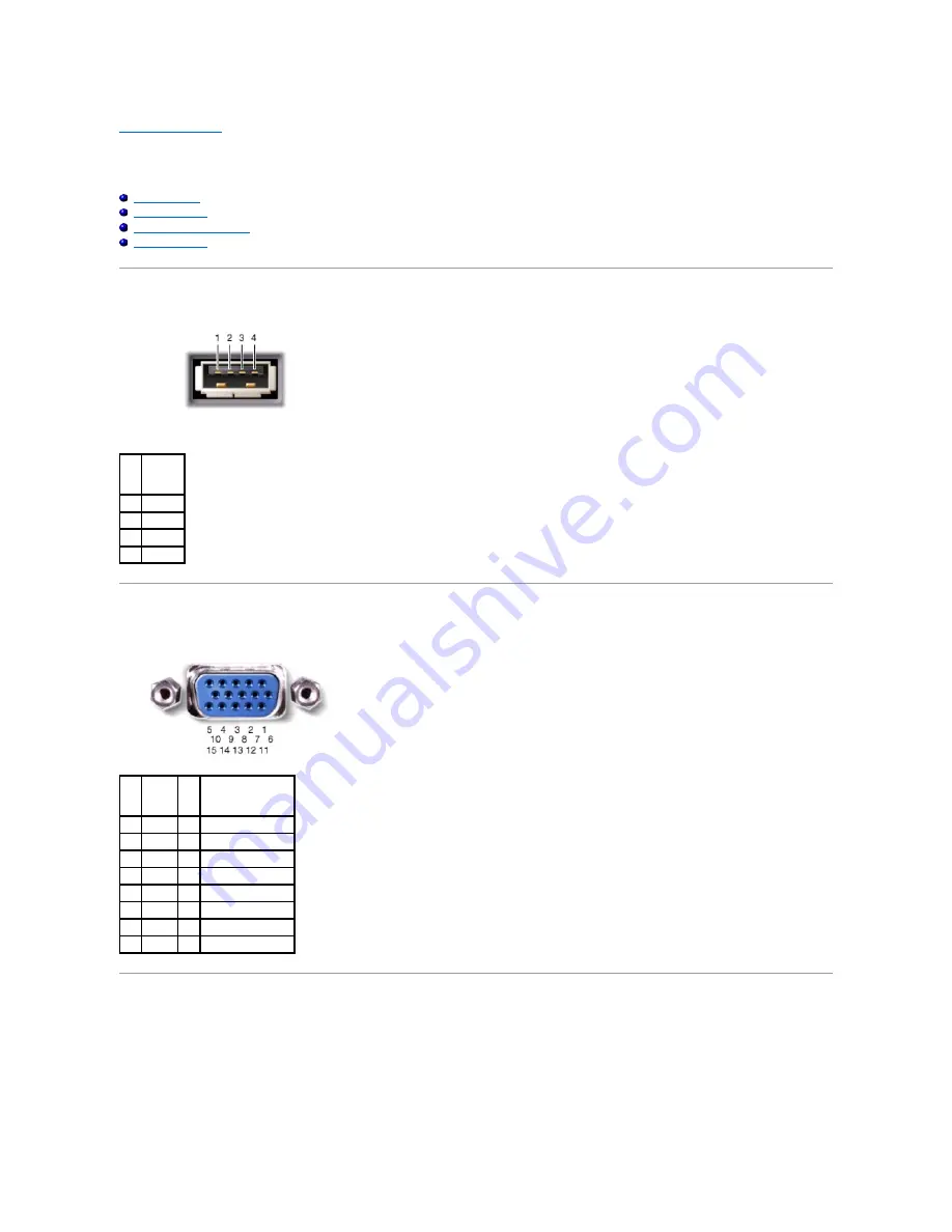
USB Connector 


Video Connector 


S-Video TV-Out Connector 


Serial Connector 


USB Connector  


Video Connector  


S-Video TV-Out Connector  


Pin 


Signal 

USB5V+ 

USBP


USBP+ 

GND 


Pin 


Signal 


Pin 


Signal 

CRT_R  9 

5V+ 

CRT_G  10  GND 

CRT_B  11  MONITOR_DETECT


NC 

12  DDC_DATA 

GND 

13  CRT_HS 

GND 

14  CRT_VS 

GND 

15  DDC_CLK 

GND 


Summary of Contents for Latitude D830 - Core 2 Duo Laptop

Page 1: ...rmission of Dell Inc is strictly forbidden Trademarks used in this text Dell the DELL logo and Latitude are trademarks of Dell Inc Bluetooth is a registered trademark owned by Bluetooth SIG Inc and is used by Dell under license Other trademarks and trade names may be used in this document to refer to either the entities claiming the marks and names or their products Dell Inc disclaims any propriet...

Page 2: ...see Palm Rest 8 Remove the processor thermal cooling assembly see Processor Thermal Cooling Assembly 9 Remove the processor see Removing the Processor Module 10 Remove the modem see Modem 11 Remove the fan see Fan 12 Remove the system board see Removing the System Board Back to Contents Page CAUTION Before performing the following procedures follow the safety instructions in the Product Informatio...

Page 3: ...mal cooling assembly see Processor Thermal Cooling Assembly 8 Remove the system board see Removing the System Board 9 To remove the battery latch use a plastic scribe or screwdriver to carefully dislodge the battery latch from the base and lift the latch away Back to Contents Page CAUTION Before performing the following procedures follow the safety instructions in the Product Information Guide NOT...

Page 4: ...ck Shut Down The computer turns off after the operating system shutdown process is complete Ensure that the computer and all attached devices are turned off If your computer and attached devices did not automatically turn off when you shut down your operating system press and hold the power button for about 4 seconds to turn them off Before Working Inside Your Computer Use the following safety gui...

Page 5: ...xpressCards PC Cards or smart cards from the computer Using Cards Computer Orientation NOTICE When you disconnect a cable pull on its connector or on its pull tab not on the cable itself Some cables have a connector with locking tabs if you are disconnecting this type of cable press in on the locking tabs before you disconnect the cable As you pull connectors apart keep them evenly aligned to avoi...

Page 6: ...Back to Contents Page 1 front 2 left 3 back 4 right ...

Page 7: ...5 Connect the new card to the card cable connector 6 Install the card by rotating and sliding it into the retention tab in the compartment 7 Replace the hinge cover see Hinge Cover Back to Contents Page CAUTION Before performing the following procedures follow the safety instructions in the Product Information Guide NOTICE To avoid electrostatic discharge ground yourself by using a wrist grounding...

Page 8: ......

Page 9: ...an installed card Striking the end of the card can damage the system board l Always remove an extended card before you pack the computer in its carrying case Installing a PC Card or ExpressCard You can install a PC Card or ExpressCard in the computer while the computer is running The computer automatically detects the card Cards are generally marked with a symbol such as a triangle or an arrow to ...

Page 10: ...river If the configuration program tells you to load the manufacturer s drivers use the floppy disk or CD that came with the card If you have an adapter such as the one shown below you can use 34 mm ExpressCards in the PC Card slot For information about using the PC Card slot see PC Card Removing a Card or Blank Press the latch and remove the card or blank For some latches you must press the latch...

Page 11: ...Back to Contents Page ...

Page 12: ... the plastic sleeve 6 Connect the cable connector to the system board 7 Replace the keyboard 8 Replace the hinge cover see Hinge Cover Back to Contents Page CAUTION Before performing the following procedures follow the safety instructions in the Product Information Guide NOTICE To avoid electrostatic discharge ground yourself by using a wrist grounding strap or by periodically touching a connector...

Page 13: ...row on the ZIF socket cam screw 8 Use a processor extraction tool to remove the processor module CAUTION Before performing the following procedures follow the safety instructions in the Product Information Guide NOTICE To avoid electrostatic discharge ground yourself by using a wrist grounding strap or by periodically touching a connector on the back panel of the computer NOTICE Press and hold the...

Page 14: ...te the BIOS using a flash BIOS update program CD see Flashing the BIOS From a CD Back to Contents Page NOTICE Ensure that the cam lock is in the fully open position before seating the processor module Seating the processor module properly in the ZIF socket does not require force NOTICE A processor module that is not properly seated can result in an intermittent connection or permanent damage to th...

Page 15: ...ck to Contents Page CAUTION Before performing the following procedures follow the safety instructions in the Product Information Guide NOTICE To avoid electrostatic discharge ground yourself by using a wrist grounding strap or by periodically touching a connector on the back panel of the computer NOTE The appearance of the thermal cooling assembly for system boards with integrated graphics varies ...

Page 16: ...eed flex cable to disconnect the cable from the system board 5 Disconnect the antenna cable s 6 Carefully remove the antenna cable and the display cables from their routing guides 7 Close the display 8 Turn the computer upside down with the back of the computer facing you 9 From the bottom of the computer remove the two M2 5 x 5 mm screws labeled D CAUTION Before performing the following procedure...

Page 17: ...isplay bumpers and two mylar screw covers from around the display bezel 4 Remove the eight M2 5 x 4 2 x 5 mm shoulder screws from around the display bezel 1 M2 5 x 5 mm screws labeled D 2 1 M2 5 x 5 mm screws 2 CAUTION Before performing the following procedures follow the safety instructions in the Product Information Guide NOTICE To avoid electrostatic discharge ground yourself by using a wrist g...

Page 18: ... Panel 1 Replace the eight M2 5 x 5 mm screws that secure the display panel to the top cover 2 Route the display feed flex cable and antenna cables so that they rest in the notch located in the bottom edge of the top cover 1 screws 8 2 display bezel 3 top cover NOTICE Carefully separate the bezel from the top cover to avoid damage to the bezel CAUTION Before performing the following procedures fol...

Page 19: ...ezel see Removing the Display Bezel 4 Remove the display panel see Removing the Display Panel 5 Remove the four M2 x 3 mm screws from the top display panel bracket and lift away the bracket CAUTION Before performing the following procedures follow the safety instructions in the Product Information Guide NOTICE To avoid electrostatic discharge ground yourself by using a wrist grounding strap or by ...

Page 20: ...de the display latch toward the right side of the top cover and straight out 7 Unhook the latch spring from the display latch and then lift away the latch Back to Contents Page 1 display latch 2 latch spring ...

Page 21: ...r cable from the system board 6 Remove the two M2 5 x 5 mm fan screws and lift the fan out of the base Back to Contents Page CAUTION Before performing the following procedures follow the safety instructions in the Product Information Guide NOTICE To avoid electrostatic discharge ground yourself by using a wrist grounding strap or by periodically touching a connector on the back panel of the comput...

Page 22: ...e card until the card pops up slightly 7 Lift the card out of its connector CAUTION Before performing the following procedures follow the safety instructions in the Product Information Guide NOTICE To avoid electrostatic discharge ground yourself by using a wrist grounding strap or by periodically touching a connector on the back panel of the computer NOTE The FCM card is also known as Intel Turbo...

Page 23: ...g this card ensure that the two antenna cables are not under the card The antenna cables are designed to lie across the top of the FCM card and into the protective sleeve Installing the card on top of these antenna cables may cause damage to your computer Also do not install the FCM card in the WLAN card connector The FCM card is designed to work in the WWAN card connector Installing the card in t...

Page 24: ... Remove the flash BIOS update program CD from the drive and restart the computer Flashing the BIOS From the Hard Drive 1 Ensure that the AC adapter is plugged in the main battery is properly installed and a network cable is attached 2 Turn on the computer 3 Locate the latest BIOS update file for your computer at support dell com 4 Click Download Now to download the file 5 If the Export Compliance ...

Page 25: ...ter when the drive is hot do not touch the metal housing of the hard drive NOTICE To prevent data loss turn off your computer before removing the hard drive Do not remove the hard drive while the computer is turned on in standby mode or in hibernate mode NOTICE Hard drives are extremely fragile even a slight bump can damage the drive NOTE Dell does not guarantee compatibility or provide support fo...

Page 26: ... 5 mm screws on the sides of the bezel 6 Slide the new hard drive into the bay and into the connector until it is fully seated 7 Replace the two M3 x 3 mm hard drive screws Back to Contents Page NOTICE Use firm and even pressure to slide the drive into place If you use excessive force you may damage the connector ...

Page 27: ...o place Back to Contents Page CAUTION Before you begin any of the procedures in this section follow the safety instructions in the Product Information Guide NOTICE To avoid electrostatic discharge ground yourself by using a wrist grounding strap or by periodically touching a connector on the back panel of the computer NOTICE The hinge cover is fragile and can be damaged if extreme force is used Be...

Page 28: ......

Page 29: ... the keyboard down on the palm rest 8 Replace the three M2 x 3 mm screws at the top of the keyboard 9 Replace the hinge cover see Hinge Cover Back to Contents Page CAUTION Before working inside your Dell computer follow the safety instructions in the Product Information Guide NOTICE To avoid electrostatic discharge ground yourself by using a wrist grounding strap or by periodically touching a conn...

Page 30: ...dule edge connector with the tab in the connector slot b Slide the module firmly into the slot at a 45 degree angle and rotate the module down until it clicks into place If you do not feel the click remove CAUTION Before you begin any of the procedures in this section follow the safety instructions in the Product Information Guide NOTICE If your computer has only one memory module install the memo...

Page 31: ...of memory installed in the computer click Start Control Panel System To install a memory module in DIMM B 1 Follow the procedures in Before You Begin 2 Turn the computer upside down loosen the captive screw on the memory module cover and then remove the cover 3 Ground yourself by touching one of the metal connectors on the back of the computer 4 If you are replacing a memory module remove the exis...

Page 32: ...f memory installed in the computer l In the Microsoft Windows XP operating system right click the My Computer icon on your desktop Click Properties General l In the Microsoft Windows Vista operating system click the Windows Vista Start button and right click Computer Properties Back to Contents Page 1 memory module 2 securing clips 2 NOTICE If you need to install memory modules in two connectors i...

Page 33: ...oard see Keyboard 4 Ground yourself by touching one of the metal connectors on the back of the computer 5 If a card is not already installed go to step 6 If you are replacing a card remove the existing card a Disconnect the antenna cables from the card b Release the card by pushing the metal securing brackets away from the card until the card pops up slightly CAUTION Before you begin any of the pr...

Page 34: ... antenna cables from the card b Release the card by pushing the metal securing brackets away from the card until the card pops up slightly 1 WLAN card 2 metal securing brackets 2 NOTICE The connectors are keyed to ensure correct insertion If you feel resistance check the connectors and realign the card NOTICE Do not insert a WWAN Mobile Broadband network card into the WLAN card slot NOTE The WLAN ...

Page 35: ...brackets 2 NOTICE The connectors are keyed to ensure correct insertion If you feel resistance check the connectors and realign the card NOTICE To avoid damaging the Mobile Broadband card never place cables on top of or under the card NOTE Most antenna connectors have color coded markings that correspond to the color of the cable For more specific information about which cable to connect to which c...

Page 36: ...Back to Contents Page 1 SIM card ...

Page 37: ...up on the pull tab to disconnect the modem from the connector on the system board 8 Disconnect the modem cable connector from the modem Back to Contents Page CAUTION Before you begin the following procedure see the safety instructions in the Product Information Guide NOTICE To avoid electrostatic discharge ground yourself by using a wrist grounding strap or by periodically touching a connector on ...

Page 38: ...e M2 5 x 5 mm screws from the top of the palm rest 9 Turn the computer bottom side up 10 Remove the eleven M2 5 x 5 mm screws from the bottom of the computer 11 Starting at the back center of the palm rest use your fingers to separate the palm rest from the base by lifting the inside edge of the palm rest CAUTION Before performing the following procedures follow the safety instructions in the Prod...

Page 39: ...he speaker connector from the system board Back to Contents Page NOTICE When replacing the palm rest ensure the cable for the internal card with Bluetooth wireless technology is properly placed on top of the palm rest to avoid damaging the cable ...

Page 40: ... M2 x 3 mm screws that secure the PC Card reader to the computer base 7 Use the pull tab to disconnect the PC Card reader cable connector from the system board Back to Contents Page CAUTION Before performing the following procedures follow the safety instructions in the Product Information Guide NOTICE To avoid electrostatic discharge ground yourself by using a wrist grounding strap or by periodic...

Page 41: ...tor Video Connector S Video TV Out Connector Serial Connector USB Connector Video Connector S Video TV Out Connector Pin Signal 1 USB5V 2 USBP 3 USBP 4 GND Pin Signal Pin Signal 1 CRT_R 9 5V 2 CRT_G 10 GND 3 CRT_B 11 MONITOR_DETECT 4 NC 12 DDC_DATA 5 GND 13 CRT_HS 6 GND 14 CRT_VS 7 GND 15 DDC_CLK 8 GND ...

Page 42: ...Serial Connector Back to Contents Page S Video Pin Signal 1 GND 2 GND 3 DLUMA L 4 DCRMA L Pin Signal Pin Signal 1 DCD 6 DSR 2 RXDA 7 RTS 3 TXDA 8 CTS 4 DTR 9 RI 5 GND ...

Page 43: ...assembly see Display Assembly 6 Remove the DIMM A and DIMM B memory modules see Memory 7 Remove any installed wireless communications cards see Communications Cards 8 Remove the palm rest see Palm Rest 9 Remove the modem see Modem 10 Remove the card reader see PC Card Reader 11 Remove the fan see Fan 12 Remove the processor thermal cooling assembly see Processor Thermal Cooling Assembly 13 Remove ...

Page 44: ...ccompanied the replacement system board into the appropriate drive Follow the instructions on the screen Back to Contents Page NOTE When installing the system board ensure that you align the wireless switch on the base with the switch on the system board 1 wireless switch NOTICE Before turning on the computer replace all screws and ensure that no stray screws remain inside the computer Failure to ...

Page 45: ...tooth SIG Inc and is used by Dell under license Other trademarks and trade names may be used in this document to refer to either the entities claiming the marks and names or their products Dell Inc disclaims any proprietary interest in trademarks and trade names other than its own Back to Contents Page NOTE A NOTE indicates important information that helps you make better use of your computer NOTI...

Reviews: