NOTE:
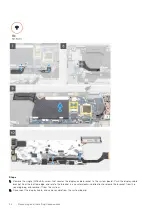
Technicians must disconnect the display cable from the system board by pulling the pull tab in a direct upward
motion to prevent damage to the connector.
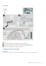
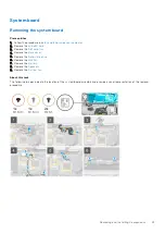
3. Remove the single (M2x2) screw that secures the wireless module bracket to the system board.
4. Lift and remove the wireless module bracket away from the system board.
5. Disconnect the Darwin antenna cables from the wireless module, and unroute the cables from the routing guides on the
system board.
6. Unroute the WWAN antenna cable from the routing guides on the system board.
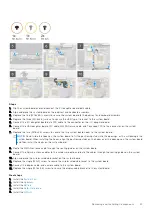
7. Remove the two (M1.6x4.5) screws that secure the two system board hooks to the system board.
8. Disconnect the USH daughter board FFC cable, WWAN Darwin cable, and touchpad FPC from the connector on the system
board.
NOTE:
To disconnect the WWAN Darwin cable from the system board, insert a plastic scribe close to the rear side of
the connector, and carefully pry in an upward direction.
9. Disconnect the I/O daughter board data FPC cable from the I/O daughter board.
10. Remove the three (M1.6x3.5) screws that secure the USB Type-C bracket to the system board.
11. Remove the five (M1.6x3.5) screws that secure the system board to the palmrest and keyboard assembly. Hold the left side
of the system board and partially lift the system board from the system.
12. Flip over the system board from the top side of the system board. Disconnect the I/O daughter board data cable, and
remove the system board from the system.
Installing the system board
Prerequisites
If you are replacing a component, remove the existing component before performing the installation procedure.
About this task
The following image indicates the location of the system board and provides a visual representation of the installation procedure.
Removing and Installing Components
45

