background image

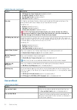
Table 13. Wireless (continued)

Option

Description

Bluetooth

Contactless Smartcard/NFC

All the options are enabled by default.

Dynamic Wireless Transmit Power

When enabled, this option allows the system to increase
transmit power or WLAN devices to improve performance
in certain system configurations within regulatory validated
guidelines.

The 

Dynamic Wireless Transmit Power

 option is enabled by

default.

Maintenance

Table 14. Maintenance  

Option

Description

Service Tag

Displays the service tag of your system. If the service tag was not already
set, this field can be used to set it.

Asset Tag

If an asset tag was not already set, this option allows you to create it. The
character limit for the password is 64 characters.

BIOS Downgrade

Allows you to flash previous revisions of the system firmware.

The 

Allow BIOS Downgrade

 option is enabled by default.

Data Wipe

Allows you to securely erase data from all internal storage devices.

The 

Wipe on Next Boot

 option is disabled by default.

WARNING:

 This operation permanently deletes all data from

the device(s).

BIOS Recovery

Allows you to recover the corrupted BIOS from a recovery file on the hard
drive or an external USB drive.

The 

BIOS Recovery from Hard Drive

 option is enabled by default.

BIOS Recovery from hard drive is not available for self-encrypting drives
(SED).

First Power On Date

Allows you to set Ownership date.

The 

Set Ownership Date

 option is disabled by default.

System logs

Table 15. System Logs 

Option

Description

BIOS events

Allows you to view and clear the System Setup (BIOS) events.

Thermal and Self-Test
Events

Allows you to view and clear the System Setup (Thermal and Self-Test) events.

Power Events

Allows you to view and clear the System Setup (Power) events.

68

System setup

Summary of Contents for Latitude 9510

Page 1: ...Latitude 9510 Service Manual Regulatory Model P94F P95F Regulatory Type P94F001 P95F001 April 2021 Rev A03 ...

Page 2: ...ential damage to hardware or loss of data and tells you how to avoid the problem WARNING A WARNING indicates a potential for property damage personal injury or death 2020 Dell Inc or its subsidiaries All rights reserved Dell EMC and other trademarks are trademarks of Dell Inc or its subsidiaries Other trademarks may be trademarks of their respective owners ...

Page 3: ...3 SIM card tray 13 MicroSD card 15 Base cover 17 WWAN card 20 Solid state drive 22 Speakers 24 System fan 27 I O daughter board power cable 29 I O board 30 Power button 32 Power button with finger print reader optional 34 Battery 36 Smart card reader 40 System board 43 Display assembly 48 Keyboard 52 Palmrest assembly 55 Chapter 4 System setup 57 Entering BIOS without keyboard 57 System setup opti...

Page 4: ...Assigning a system setup password 71 Deleting or changing an existing system setup password 71 Chapter 5 Troubleshooting 73 Dell SupportAssist Pre boot System Performance Check diagnostics 73 Running the SupportAssist Pre Boot System Performance Check 73 System diagnostic lights 73 Flashing BIOS USB key 74 Flashing the BIOS 75 Backup media and recovery options 75 WiFi power cycle 75 Flea power rel...

Page 5: ...ing inside your computer ground yourself by touching an unpainted metal surface such as the metal at the back of the computer While you work periodically touch an unpainted metal surface to dissipate static electricity which could harm internal components CAUTION When you disconnect a cable pull it by its connector or its pull tab not the cable itself Some cables have connectors with locking tabs ...

Page 6: ...ithout disconnecting the battery cable or removing the battery from the system Steps 1 Shut down the system and disconnect the AC adapter from the system 2 Press and hold the B key on the keyboard and then press the power button The system will boot 3 Press any key to proceed when the Owner Tag information is displayed on the screen The system will emit three short beeps and shuts down 6 Working o...

Page 7: ...the same electrical potential This is done through the use of a field service electrostatic discharge ESD kit When connecting a bonding wire ensure that it is connected to bare metal and never to a painted or non metal surface The wrist strap should be secure and in full contact with your skin and ensure that you remove all jewelry such as watches bracelets or rings prior to bonding yourself and t...

Page 8: ...ternal wires of a wrist strap are prone to damage from normal wear and tear and must be checked regularly with a wrist strap tester in order to avoid accidental ESD hardware damage It is recommended to test the wrist strap and bonding wire at least once per week ESD Wrist Strap Tester The wires inside of an ESD strap are prone to damage over time When using an unmonitored kit it is a best practice...

Page 9: ...ng sensitive components After working inside your computer About this task NOTE Leaving stray or loose screws inside your computer may severely damage your computer Steps 1 Replace all screws and ensure that no stray screws remain inside your computer 2 Connect any external devices peripherals or cables you removed before working on your computer 3 Replace any media cards discs or any other parts ...

Page 10: ...assembly 9 LCD panel 10 Keyboard 11 I O board 12 System fan 13 Battery 14 Speaker NOTE Dell provides a list of components and their part numbers for the original system configuration purchased These parts are available according to warranty coverages purchased by the customer Contact your Dell sales representative for purchase options 2 10 Major components of your system ...

Page 11: ...hen removing screws from a component it is recommended to note the screw type the quantity of screws and then place them in a screw storage box This is to ensure that the correct number of screws and correct screw type is restored when the component is replaced NOTE Some systems have magnetic surfaces Ensure that the screws are not left attached to such surface when replacing a component 3 Removin...

Page 12: ...ws 9 4 cell battery M1 6x3 5 1 M2x3 4 6 cell battery M1 6x3 5 1 M2x3 8 WWAN Captive screw 1 M1 6x4 5 1 Smart card reader M2x2 2 Solid state drive M2x2 1 Speaker M1 6x1 8 4 I O board M1 6x3 5 4 System fan M2x3 2 Display cable bracket M1 6x3 5 1 Display assembly M2 5x5 6 M1 6x3 5 1 Power button M1 5x2 5 3 M2 5x5 3 12 Removing and Installing Components ...

Page 13: ...2 5x5 1 M1 6x4 5 1 Keyboard M1 6x2 4 M1 6x1 5 36 Disassembly and reassembly SIM card tray Removing the SIM card tray Prerequisites Follow the procedure in before working inside your computer About this task The following image provides a visual representation of the SIM card tray removal procedure Removing and Installing Components 13 ...

Page 14: ...lide the SIM card tray out of the slot on the system 3 Installing the SIM card tray Prerequisites If you are replacing a component remove the necessary component before the installation procedure About this task The following image provides a visual representation of the SIM card tray installation procedure 14 Removing and Installing Components ...

Page 15: ...h it to lock in place 3 Next steps Follow the procedure in After working on your computer MicroSD card Removing the microSD card Prerequisites Follow the procedure in before working inside your computer About this task The following image provides a visual representation of the microSD card removal procedure Removing and Installing Components 15 ...

Page 16: ...2 Installing the microSD card Prerequisites If you are replacing a component remove the existing component before performing the installation procedure About this task The following image provides a visual representation of the microSD card installation procedure 16 Removing and Installing Components ...

Page 17: ...eps 1 Follow the procedure in After working on your computer Base cover Removing the base cover Prerequisites 1 Follow the procedure in before working inside your computer 2 Remove the microSD card 3 Remove the SIM card tray 4 Enter service mode Removing and Installing Components 17 ...

Page 18: ...About this task 18 Removing and Installing Components ...

Page 19: ... top side immediately after prying it from the recesses as this will cause damage to the base cover 3 Pry open the left and right sides of the base cover 4 Pry open the bottom side of the base cover 5 Hold the left and right sides of the base cover and remove it from the system Installing the base cover Prerequisites If you are replacing a component remove the existing component before performing ...

Page 20: ...D card 3 Follow the procedure in After working on your computer WWAN card Removing the WWAN card Prerequisites 1 Follow the procedure in before working inside your computer 2 Remove the microSD card 3 Remove the SIM card tray 4 Enter service mode 5 Remove the base cover About this task The following images indicate the location of the WWAN card and provide a visual representation of the removal pr...

Page 21: ...antenna cables from the connectors on the WWAN card 5 Slide and remove the WWAN card from the WWAN card slot Installing the WWAN card Prerequisites If you are replacing a component remove the existing component before performing the installation procedure About this task The following image indicates the location of the WWAN card and provides a visual representation of the installation procedure R...

Page 22: ...ghten the single captive screw 5 Align and place the WWAN card shield press to fit it firmly to cover the WWAN card Next steps 1 Install the Base cover 2 Install the SIM card tray 3 Install the microSD card 4 Follow the procedure in After working on your computer Solid state drive Removing the solid state drive Prerequisites 1 Follow the procedure in before working inside your computer 2 Remove th...

Page 23: ...gle screw M2x2 that secures the solid state drive to the system board 3 Slide and remove the solid state drive from the solid state drive slot on the system board Installing the solid state drive Prerequisites If you are replacing a component remove the existing component before performing the installation procedure About this task The following image indicates the location of the solid state driv...

Page 24: ...ace the solid state drive shield press to fit it firmly to cover the solid state drive Next steps 1 Install the Base cover 2 Install the SIM card tray 3 Install the microSD card 4 Follow the procedure in After working on your computer Speakers Removing the speaker Prerequisites 1 Follow the procedure in before working inside your computer 2 Remove the microSD card 3 Remove the SIM card tray 4 Ente...

Page 25: ... and unroute the speaker cable from the routing guide 3 Remove the four M1 6x1 8 screws that secure the speakers and remove the speakers from the system Installing the speaker Prerequisites If you are replacing a component remove the existing component before performing the installation procedure About this task The following image indicates the location of the speaker and provides a visual repres...

Page 26: ... Route the speaker cables through the routing guide and connect the speaker cable to the connector 4 Adhere the adhesive tape to secure the speaker cable Next steps 1 Install the Base cover 2 Install the SIM card tray 3 Install the microSD card 4 Follow the procedure in After working on your computer 26 Removing and Installing Components ...

Page 27: ...es indicate the location of the system fan and provide a visual representation of the removal procedure Steps 1 Disconnect the I O cable and unroute the antenna cable through the routing guide 2 Disconnect the system fan cable from the connector and peel the adhesive tape securing the system fan cable 3 Remove the two M2x3 screws that secure the system fan 4 Lift the system fan off the palmrest as...

Page 28: ...tem fan onto the palmrest assembly 2 Replace the two M2x3 screws that secure the system fan in place 3 Connect the system fan cable and adhere the adhesive tape to secure the system fan cable 4 Route the antenna cable through the routing guide and connect the I O cable NOTE Reconnect the battery after system repair Next steps 1 Install the Speakers 2 Install the Base cover 3 Install the SIM card t...

Page 29: ...s 1 Disconnect the I O daughter board power cable from the I O board and system board 2 Unroute the I O daughter board power cable from the routing channels adjacent to the system fan 3 Remove the I O daughter board power cable from the system Installing the I O daughter board power cable Prerequisites If you are replacing a component remove the existing component before performing the installatio...

Page 30: ...ard 4 Follow the procedure in After working on your computer I O board Removing the I O board Prerequisites 1 Follow the procedure in before working inside your computer 2 Remove the microSD card 3 Remove the SIM card tray 4 Enter service mode 5 Remove the Base cover 6 Remove the System Fan About this task The following image indicates the location of the I O board and provides a visual representa...

Page 31: ... the I O board out of the laptop Installing the I O board Prerequisites If you are replacing a component remove the existing component before performing the installation procedure About this task The following image indicates the location of the I O board and provides a visual representation of the installation procedure Removing and Installing Components 31 ...

Page 32: ...the Base cover 3 Install the SIM card tray 4 Install the microSD card 5 Follow the procedure in After working on your computer Power button Removing the power button Prerequisites 1 Follow the procedure in before working inside your computer 2 Remove the microSD card 3 Remove the SIM card tray 4 Enter service mode 5 Remove the Base cover 6 Remove the Fan 7 Remove the I O board About this task The ...

Page 33: ...system 3 Peel off the power button assembly from the palm rest and remove the power button assembly from the system Installing the power button About this task The following image indicate the location of the power button and provide a visual representation of the installation procedure Removing and Installing Components 33 ...

Page 34: ...SD card 6 Follow the procedure in After working on your computer Power button with finger print reader optional Removing the power button with fingerprint reader Prerequisites 1 Follow the procedure in before working inside your computer 2 Remove the microSD card 3 Remove the SIM card tray 4 Enter service mode 5 Remove the Base cover 6 Remove the system fan 7 Remove the I O board About this task T...

Page 35: ...performing the installation procedure About this task The following images indicate the location of the fingerprint reader and provide a visual representation of the installation procedure Steps 1 Align and place the fingerprint reader assembly on the system and adhere the power button with the fingerprint reader assembly on the sponge on the palmrest 2 Align and place the fingerprint reader brack...

Page 36: ...misplaced to prevent accidental puncture or damage to the battery and other system components If the battery gets stuck inside your computer as a result of swelling do not try to release it as puncturing bending or crushing a lithium ion battery can be dangerous In such an instance contact Dell technical support for assistance See www dell com contactdell Always purchase genuine batteries from www...

Page 37: ...bles from their routing guides while they are still attached to the wireless card 2 Remove the single M1 6x3 5 screw and four M2x3 screws that secures the battery 3 Lift the battery from the left side of the system and remove the battery from the laptop Installing the 4 cell battery Prerequisites If you are replacing a component remove the existing component before performing the installation proc...

Page 38: ... side on the laptop 2 Replace the single M1 6x3 5 screw and four M2x3 screws to secure the battery in place 3 Route the wireless antenna cables on the routing guides and adhere the adhesive tape Next steps 1 Install the Speakers 2 Install the Base cover 3 Install the SIM card tray 4 Install the microSD card 5 Follow the procedure in After working on your computer 38 Removing and Installing Compone...

Page 39: ...ables in place and unroute the wireless antenna cables from the routing guides NOTE The cables for the wireless antennas are routed over the plastic bracket at the upper left corner and within the routing channels along the left and bottom side of the battery Technicians must be careful when unrouting the antenna cables from their routing guides while they are still attached to the wireless card 2...

Page 40: ...reless antenna cables on the routing guides and adhere the adhesive tape Next steps 1 Install the Speakers 2 Install the Base cover 3 Install the SIM card tray 4 Install the microSD card 5 Follow the procedure in After working on your computer Smart card reader Removing the smart card reader Prerequisites 1 Follow the procedure in before working inside your computer 2 Remove the microSD card 3 Rem...

Page 41: ...e I O daughter board 3 Remove the two screws M2x2 that secure the smart card reader to the palmrest assembly 4 Lift the smart card reader away from the palmrest assembly Installing the smart card reader Prerequisites If you are replacing a component remove the existing component before performing the installation procedure Removing and Installing Components 41 ...

Page 42: ...card reader cable to the connector on the I O daughter board and close the latch 4 Connect the touchpad FPC to the connector on the system board and close the latch Next steps 1 Install the Speakers 2 Install the Battery 3 Install the Base cover 4 Install the SIM card tray 5 Install the microSD card 6 Follow the procedure in After working on your computer 42 Removing and Installing Components ...

Page 43: ...ove the SIM card tray 4 Remove the Base cover 5 Remove the Solid state drive 6 Remove the WWAN 7 Remove the Battery 8 Remove the Speakers 9 Remove the System Fan About this task The following images indicate the location of the system board assembly and provide a visual representation of the removal procedure Removing and Installing Components 43 ...

Page 44: ...board Push the display cable bracket from the bottom edge and rotate the bracket in a counterclockwise direction to release the bracket from the securing peg and remove it from the system 2 Disconnect the display cable and camera cable from the system board 44 Removing and Installing Components ...

Page 45: ...le from the system board insert a plastic scribe close to the rear side of the connector and carefully pry in an upward direction 9 Disconnect the I O daughter board data FPC cable from the I O daughter board 10 Remove the three M1 6x3 5 screws that secure the USB Type C bracket to the system board 11 Remove the five M1 6x3 5 screws that secure the system board to the palmrest and keyboard assembl...

Page 46: ...46 Removing and Installing Components ...

Page 47: ...ing studs into the openings as this will damage the system board When installing the hooks align the positioning studs on the hooks over the openings on the system board and then install the hooks on the system board 8 Route the WWAN antenna cable through the routing guides on the system board 9 Connect the Darwin antenna cables to the wireless module and route the cables through the routing guide...

Page 48: ...ure in before working inside your computer 2 Remove the microSD card 3 Remove the SIM card tray 4 Remove the Base cover 5 Remove the Battery About this task The following images indicate the location of the display assembly and provide a visual representation of the removal procedure NOTE The display assembly removal procedure is the same for both laptop and convertible chassis 48 Removing and Ins...

Page 49: ...Removing and Installing Components 49 ...

Page 50: ...m and then place the system on a flat surface 4 Remove the six M2 5x5 screws that secure the display assembly to the laptop press the edges of the laptop near the hinges and lift the hinges in the upward direction away from the laptop 5 Lift the display assembly off the laptop Installing the display assembly Prerequisites If you are replacing a component remove the existing component before perfor...

Page 51: ...Removing and Installing Components 51 ...

Page 52: ...the display cable bracket in place and install the single M1 6x3 5 screw securing the display cable bracket Next steps 1 Install the Battery 2 Install the Base cover 3 Install the SIM card tray 4 Install the microSD card 5 Follow the procedure in After working on your computer Keyboard Removing the keyboard Prerequisites 1 Follow the procedure in before working inside your computer 2 Remove the mi...

Page 53: ...e location of the keyboard and provide a visual representation of the removal procedure Steps 1 Peel back the antenna cable WWAN Darwin cable touchpad FPC LED FFC from the keyboard 2 Disconnect the backlight cable and the keyboard cable from the connectors on the touchpad 3 Remove the four M1 6x2 and thirty six M1 6x1 5 screws that secures the keyboard to the palmrest 4 Lift the keyboard from the ...

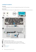
Page 54: ... representation of the installation procedure Steps 1 Align and place the keyboard on the palmrest 2 Install the four M1 6x2 and thirty six M1 6x1 5 screws to secure the keyboard 3 Connect the keyboard cable and backlight cable to the connectors on the touchpad 4 Adhere the antenna cable WWAN Darwin cable touchpad FPC LED FFC to the keyboard Next steps 1 Install the System board 2 Install the I O ...

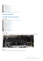
Page 55: ... your computer 2 Remove the microSD card 3 Remove the SIM card tray 4 Remove the Base cover 5 Remove the Solid state drive 6 Remove the Speakers 7 Remove the Battery 8 Remove the Display assembly 9 Remove the System Fan 10 Remove the I O board 11 Remove the Power button 12 Remove the System board 13 Remove the Keyboard About this task The following images indicate the location of the palmrest and ...

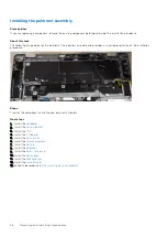
Page 56: ...ation procedure Steps Transfer the components onto the new palmrest assembly Next steps 1 Install the Keyboard 2 Install the System board 3 Install the FPC 4 Install the I O board 5 Install the System Fan 6 Install the Display assembly 7 Install the Battery 8 Install the Speakers 9 Install the Solid state drive 10 Install the Base cover 11 Install the SIM card tray 12 Install the microSD card 13 F...

Page 57: ...the Volume Down button to enter BIOS setup program System setup options NOTE Depending on the tabletcomputerlaptop and its installed devices the items listed in this section may or may not appear General options Table 2 General Option Description System Information This section lists the primary hardware features of your computer The options are System Information Memory information Processor Info...

Page 58: ...on enabled by default Drives These fields let you enable or disable various drives on board The M 2 PCIe SSD 0 option is enabled by default SMART Reporting This field controls whether hard drive errors for integrated drives are reported during startup The option Enable SMART Reporting is disabled by default USB Configuration Allows you to configure the integrated USB controller The options are Ena...

Page 59: ...llumination will always be off or 0 Dim disabled by default Enable the keyboard illumination feature at 50 brightness Bright enabled by default Enable the keyboard illumination feature at 100 brightness level Keyboard Backlight Timeout on AC This feature defines the timeout value for the keyboard backlight when an AC adapter is plugged into the system Options are 5 seconds 10 seconds enabled by de...

Page 60: ...ows you to set the display brightness depending upon the power source on Battery 50 is set as default and on AC 100 is set as default Security Table 5 Security Option Description Admin Password Allows you to set change or delete the administrator admin password sometimes called setup password The entries to set the password are Enter the old password NOTE For the first time login Enter the old pas...

Page 61: ...ed by default NOTE The system always prompts for the System and internal HDD passwords when powered on from the off state a cold boot The system always prompts for passwords on any module bay HDDs that may be present Password Change Allows you to change the System and Hard Disk password when the administrator password is set The Allow Non Admin Password Changes option is enabled by default UEFI Ca...

Page 62: ... default Admin Setup Lockout Allows you to prevent users from entering Setup when an admin password is set The Enable Admin Setup Lockout option disabled by default Master Password Lockout Allows you to disable master password support The Enable Master Password Lockout option is disabled by default NOTE Hard Disk password should be cleared before the settings can be changed SMM Security Mitigation...

Page 63: ...e main operating systems Click one of the following options Disabled Enabled Software controlled enabled by default Enclave Memory Size This option shows the SGX Enclave Reserve Memory Size The Enclave Memory Size is 128 MB Performance Table 8 Performance Option Description Multi Core Support This field specifies whether the processor has one or all cores enabled The performance of some applicatio...

Page 64: ...ery AC Behavior Allows the system if Off or in Hibernate to power on automatically when an AC adapter is connected The Wake on AC option is disabled by default Enable Intel Speed Shift technology This option is used to enable or disable Intel Speed Shift Technology support The Enable Intel Speed Shift Technology option is enabled by default Auto On Time Allows you to set the time at which the syst...

Page 65: ...efault This option sets the battery threshold value 15 to 100 The battery threshold value is set at 15 by default The Enable Peak Shift option is disabled by default Advanced Battery Charge Configuration This option enables you to maximize the battery health while still supporting heavy use during the work day By enabling this option your system uses the standard charging algorithm and other techn...

Page 66: ...Allows you to create an additional preboot delay and see POST status messages Click one of the following options 0 seconds enabled by default 5 seconds 10 seconds Warnings and Errors Allows you to select different options to either stop prompt and wait for user input continue when warnings are detected but pause on errors or continue when either warnings or errors are detected during the POST proc...

Page 67: ...enabled by default NOTE Trusted Execution requires Virtualization Technology to be enabled VT for Direct I O Enables or disables the Virtual Machine Monitor VMM from utilizing the additional hardware capabilities that are provided by the Intel Virtualization Technology for direct I O NOTE Trusted Execution requires VT for Direct I O to be enabled The Enable VT for Direct I O option is enabled by d...

Page 68: ...sions of the system firmware The Allow BIOS Downgrade option is enabled by default Data Wipe Allows you to securely erase data from all internal storage devices The Wipe on Next Boot option is disabled by default WARNING This operation permanently deletes all data from the device s BIOS Recovery Allows you to recover the corrupted BIOS from a recovery file on the hard drive or an external USB driv...

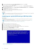
Page 69: ... Setup Thermal events Power Events Allows you to view and clear the System Setup Power events Updating the BIOS Prerequisites It is recommended to update your BIOS System setup on replacing the system board or if an update is available Ensure that your tabletnotebookdesktop battery is fully charged and connected to a power outlet Steps 1 Restart the tabletnotebookdesktop 2 Go to Dell com support 3...

Page 70: ...pdating your system BIOS using a USB flash drive About this task If the system cannot load into Windows but there is still a need to update the BIOS download the BIOS file using another system and save it to a bootable USB Flash Drive NOTE You will need to use a bootable USB flash drive Please refer to the following article for further details How to Create a Bootable USB Flash Drive using Dell Di...

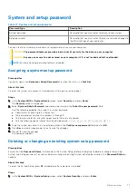
Page 71: ...urity screen is displayed 2 Select System Admin Password and create a password in the Enter the new password field Use the following guidelines to assign the system password A password can have up to 32 characters The password can contain the numbers 0 through 9 Only lower case letters are valid upper case letters are not allowed Only the following special characters are allowed space 3 Type the s...

Page 72: ...lect Setup Password alter or delete the existing setup password and press Enter or Tab NOTE If you change the System and or Setup password re enter the new password when prompted If you delete the System and Setup password confirm the deletion when prompted 5 Press Esc and a message prompts you to save the changes 6 Press Y to save the changes and exit from System Setup The computer restarts 72 Sy...

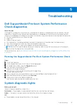
Page 73: ...are performed For more information see Resolve Hardware Issues With Built in and Online Diagnostics SupportAssist ePSA ePSA or PSA Error Codes Running the SupportAssist Pre Boot System Performance Check Steps 1 Turn on your computer 2 As the computer boots press the F12 key as the Dell logo appears 3 On the boot menu screen select the Diagnostics option 4 Click the arrow at the bottom left corner ...

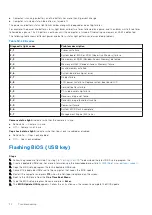
Page 74: ...n cell battery failure 3 2 PCI video card chip failure 3 3 Recovery image not found 3 4 Recovery image found but invalid 3 5 Power rail failure 3 6 System BIOS Flash incomplete 3 7 Management Engine ME error Camera status light Indicates whether the camera is in use Solid white Camera is in use Off Camera is not in use Caps Lock status light Indicates whether Caps Lock is enabled or disabled Solid...

Page 75: ... It is recommended to create a recovery drive to troubleshoot and fix problems that may occur with Windows Dell proposes multiple options for recovering Windows operating system on your Dell PC For more information see Dell Windows Backup Media and Recovery Options WiFi power cycle About this task If your computer is unable to access the internet due to WiFi connectivity issues a WiFi power cycle ...

Page 76: ...r computer 2 Disconnect the power adapter from your computer 3 Press and hold the power button for 15 seconds to drain the flea power 4 Connect the power adapter to your computer 5 Turn on your computer 76 Troubleshooting ...

Page 77: ...ne based support and service options Availability varies by country and product and some services may not be available in your area To contact Dell for sales technical support or customer service issues Steps 1 Go to Dell com support 2 Select your support category 3 Verify your country or region in the Choose a Country Region drop down list at the bottom of the page 4 Select the appropriate servic...

Reviews: