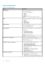

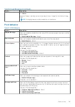
System configuration
Table 10. System Configuration
Option
Description
SATA Operation
Allows you to configure the operating mode of the integrated
SATA hard-drive controller.
Click one of the following options:
●
Disabled
●
AHCI
●
RAID On
—Default
NOTE:
SATA is configured to support RAID mode.
Drives
These fields let you enable or disable various drives on board.
The options are:
●
SATA-2
●
M.2 PCIe SSD-0
●
M.2 PCIe SSD-1
SMART Reporting
This field controls whether hard drive errors for integrated
drives are reported during startup.
The option is disabled by default.
USB Configuration
Allows you to enable or disable the internal/integrated USB
configuration.
The options are:
●
Enable USB Boot Support
●
Enable External USB Ports
All the options are set by default.
NOTE:
USB keyboard and mouse always work in the BIOS
setup irrespective of these settings.
Dell Type-C Dock Configuration
Allows you to connect to Dell WD and TB family of
docks(Type-C Docks) independent of USB and thunderbolt
adapter configuration.
This option is enabled by default.
Thunderbolt™ Adapter Configuration
Allows you to enable or disable Thunderbolt options:
●
Thunderbolt (Enabled by Defualt)
●
Enable Thunderbolt Boot Support
●
Enable Thunderbolt (and PCIe behind TBT) Pre-boot
With following security levels :
●
No Security
●
User Authentication (Enabled by Defualt)
●
Secure Connect
●
Display Port and USB Only
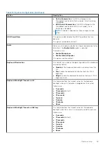
Thunderbolt™ Auto Switch
This option configures the method used by the Thunderbolt
controller to perform PCIe device enumeration.
●
Auto Switch
: The BIOS will automatically switch
between BIOS Assist and Native Thunderbolt PC device
enumeration modes to get all benefits of the installed OS
98
System setup
Summary of Contents for Latitude 7400 2-in-1
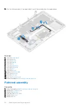
Page 24: ...4 Pry along the left right and bottom edges of the base 24 Removing and installing components ...
Page 43: ...5 Place the metal shield on the WWAN card Removing and installing components 43 ...
Page 51: ...8 Adhere the Mylar sheet on the system board Removing and installing components 51 ...
Page 56: ...4 Remove the metal foil from the heatsink shield 56 Removing and installing components ...
Page 57: ...5 Remove the heatsink shield from the system board Removing and installing components 57 ...
Page 60: ...3 Place the heatsink shield on the heatsink 60 Removing and installing components ...
Page 61: ...4 Adhere the metal foils on the heatsink shield Removing and installing components 61 ...
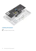
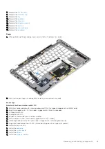
Page 87: ...8 Lift the keyboard off the palmrest assembly Removing and installing components 87 ...


