background image

Assigning a System Password and Setup Password

You can assign a new System Password and/or Setup Password or change an existing System Password and/or Setup 
Password only when Password Status is Unlocked. If the Password Status is Locked, you cannot change the System 
Password.

NOTE: If the password jumper is disabled, the existing System Password and Setup Password is deleted and you 
need not provide the system password to log on to the computer.

To enter a system setup, press <F2> immediately after a power-on or re-boot.

1.

In the System BIOS or System Setup screen, select System Security and press <Enter>.
The System Security screen appears.

2.

In the System Security screen, verify that Password Status is Unlocked.

3.

Select System Password , enter your system password, and press <Enter> or <Tab>.
Use the following guidelines to assign the system password:

– A password can have up to 32 characters.
– The password can contain the numbers 0 through 9.
– Only lower case letters are valid, upper case letters are not allowed.
– Only the following special characters are allowed: space, (”), (+), (,), (-), (.), (/), (;), ([), (\), (]), (`).

Re-enter the system password when prompted.

4.

Type the system password that you entered earlier and click OK.

5.

Select Setup Password, type your system password and press <Enter> or <Tab>.
A message prompts you to re-type the setup password.

6.

Type the setup password that you entered earlier and click OK.

7.

Press <Esc> and a message prompts you to save the changes.

8.

Press <Y> to save the changes.
The computer reboots.

Deleting or Changing an Existing System and/or Setup Password

Ensure that the Password Status is Unlocked (in the System Setup) before attempting to delete or change the existing 
System and/or Setup password. You cannot delete or change an existing System or Setup password, if the Password 
Status is Locked.

To enter the System Setup, press <F2> immediately after a power-on or reboot.

1.

In the System BIOS or System Setup screen, select System Security and press <Enter>.
The System Security screen is displayed.

2.

In the System Security screen, verify that Password Status is Unlocked.

3.

Select System Password, alter or delete the existing system password and press <Enter> or <Tab>.

4.

Select Setup Password, alter or delete the existing setup password and press <Enter> or <Tab>.

NOTE: If you change the System and/or Setup password, re-enter the new password when promoted. If you 
delete the System and/or Setup password, confirm the deletion when promoted.

5.

Press <Esc> and a message prompts you to save the changes.

46

Summary of Contents for Latitude 3540

Page 1: ...Dell Latitude 3540 Owner s Manual Regulatory Model P28F Regulatory Type P28F004 ...

Page 2: ...problem WARNING A WARNING indicates a potential for property damage personal injury or death Copyright 2014 Dell Inc All rights reserved This product is protected by U S and international copyright and intellectual property laws Dell and the Dell logo are trademarks of Dell Inc in the United States and or other jurisdictions All other marks and names mentioned herein may be trademarks of their res...

Page 3: ...emoving the Hard Drive 13 Installing the Hard Drive 14 Removing the Optical Drive 15 Installing the Optical Drive 15 Removing the Keyboard 16 Installing the Keyboard 17 Removing the WLAN Card 17 Installing the WLAN Card 17 Removing the Palmrest 18 Installing the Palmrest 20 Removing the Input Output I O Board 20 Installing the Input Output I O Board 21 Removing the System Board 21 Installing the S...

Page 4: ... Display Panel 36 Installing the Display Panel 37 Removing the Camera Module 38 Installing the Camera Module 39 3 System Setup 41 Boot Sequence 41 Navigation Keys 41 System Setup Options 42 Updating the BIOS 45 System and Setup Password 45 Assigning a System Password and Setup Password 46 Deleting or Changing an Existing System and or Setup Password 46 4 Troubleshooting 49 Enhanced Pre Boot System...

Page 5: ...face such as a connector on the back of the computer CAUTION Handle components and cards with care Do not touch the components or contacts on a card Hold a card by its edges or by its metal mounting bracket Hold a component such as a processor by its edges not by its pins CAUTION When you disconnect a cable pull on its connector or on its pull tab not on the cable itself Some cables have connector...

Page 6: ... installed ExpressCards or Smart Cards from the appropriate slots Turning Off Your Computer CAUTION To avoid losing data save and close all open files and exit all open programs before you turn off your computer 1 Shut down the operating system In Windows 8 Using a touch enabled device a Swipe in from the right edge of the screen opening the Charms menu and select Settings b Select the and then se...

Page 7: ...ot use batteries designed for other Dell computers 1 Connect any external devices such as a port replicator battery slice or media base and replace any cards such as an ExpressCard 2 Connect any telephone or network cables to your computer CAUTION To connect a network cable first plug the cable into the network device and then plug it into the computer 3 Replace the battery 4 Connect your computer...

Page 8: ...8 ...

Page 9: ...stalling Components This section provides detailed information on how to remove or install the components from your computer System Overview 1 memory module s 2 SD card slot 3 hard drive 4 optical drive 5 battery bay 9 ...

Page 10: ...ools The procedures in this document may require the following tools Small flat blade screwdriver 0 Phillips screwdriver 1 Phillips screwdriver Small plastic scribe Removing the SD Card 1 Follow the procedures in Before Working Inside Your Computer 2 Press in on the SD memory card to release it from the computer 10 ...

Page 11: ...Before Working Inside Your Computer 2 Slide the release latches outwards to unlock the battery and lift the battery to remove it from the computer Installing the Battery 1 Slide the battery into its slot until it clicks into place 2 Follow the procedures in After Working Inside Your Computer Removing the Access Panel 1 Follow the procedures in Before Working Inside Your Computer 2 Remove the batte...

Page 12: ...e the access panel to the computer 3 Install the battery 4 Follow the procedures in After Working Inside Your Computer Removing the Memory Module 1 Follow the procedures in Before Working Inside Your Computer 2 Remove a battery b SD card c access panel 3 Pry the securing clips away from the memory module until it pops up Remove the memory module from its socket on the system board 12 ...

Page 13: ... place 2 Install a access panel b SD card c battery 3 Follow the procedures in After Working Inside Your Computer Removing the Hard Drive 1 Follow the procedures in Before Working Inside Your Computer 2 Remove a battery b SD card c access panel 3 Remove the screws that secure the hard drive to the computer 13 ...

Page 14: ...et from the hard drive Installing the Hard Drive 1 Place the hard drive in the hard drive bracket and secure the latch 2 Tighten the screws to secure the hard drive bracket to the hard drive 3 Slide the hard drive in its slot in the computer 4 Tighten the screws to secure the hard drive to the computer 5 Install a access panel b SD card c battery 6 Follow the procedures in After Working Inside You...

Page 15: ...bracket to the optical drive Remove the optical drive bracket from the optical drive Installing the Optical Drive 1 Place the optical drive bracket on to the optical drive 2 Tighten the screws to secure the optical drive bracket to the optical drive 3 Slide the optical drive into the drive bay in the computer 4 Tighten the screw to secure the optical drive to the computer 5 Install the battery 6 F...

Page 16: ...ow the procedures in Before Working Inside Your Computer 2 Remove the battery 3 Release the keyboard by pressing the tabs on the palmrest 4 Slide the keyboard towards the display assembly and flip the keyboard over the palmrest 16 ...

Page 17: ...r Working Inside Your Computer Removing the WLAN Card 1 Follow the procedures in Before Working Inside Your Computer 2 Remove a battery b keyboard 3 Disconnect the antenna cables remove the screw that secures the WLAN card to the system board and lift the WLAN card from the computer Installing the WLAN Card 1 Insert the WLAN card in its connector at a 45 degree angle in its slot 2 Connect the ante...

Page 18: ...r Working Inside Your Computer Removing the Palmrest 1 Follow the procedures in Before Working Inside Your Computer 2 Remove a battery b SD card c access panel d hard drive e optical drive f keyboard 3 Remove the screws that secure the palmrest to the computer 18 ...

Page 19: ...er and disconnect the touchpad cable and power button cable from the system board 5 Remove the screws that secure the palmrest to the system board Lift and release the tabs on palmrest from the slots on the computer 19 ...

Page 20: ...oard 3 Tighten the screws to secure the palmrest to the system board 4 Flip the computer and tighten the screws to secure the palmrest to the computer 5 Install a keyboard b optical drive c hard drive d access panel e SD card f battery 6 Follow the procedures in After Working Inside Your Computer Removing the Input Output I O Board 1 Follow the procedures in Before Working Inside Your Computer 2 R...

Page 21: ...en the screw to secure the I O board to the computer 3 Connect the I O cable to the system board 4 Install a palmrest b keyboard c access panel d battery 5 Follow the procedures in After Working Inside Your Computer Removing the System Board 1 Follow the procedures in Before Working Inside Your Computer 2 Remove a SD card b battery c access panel d memory module e hard drive f optical drive g keyb...

Page 22: ...board cable e Touch cable for touch computer only 4 Remove the screw that secures the system board to the computer Lift the system board from the computer Installing the System Board 1 Align the system board in its place on the computer 2 Tighten the screw to secure the system board to the computer 22 ...

Page 23: ...drive f memory module g access panel h battery i SD card 5 Follow the procedures in After Working Inside Your Computer Removing the Coin Cell Battery 1 Follow the procedures in Before Working Inside Your Computer 2 Remove a battery b access panel c memory module d hard drive e optical drive f keyboard g palmrest h WLAN card i system board 3 Flip the system board and place it on a flat surface 4 Pr...

Page 24: ...es in After Working Inside Your Computer Removing the Heatsink 1 Follow the procedures in Before Working Inside Your Computer 2 Remove a SD card b battery c access panel d memory module e hard drive f optical drive g keyboard h palmrest i WLAN card j system board 3 Flip the system board and place it on a flat surface 4 Remove the screws that secure the heatsink to the system board Lift the heatsin...

Page 25: ... keyboard d optical drive e hard drive f memory module g WLAN card h access panel i SD card j battery 4 Follow the procedures in After Working Inside Your Computer Removing the System Fan 1 Follow the procedures in Before Working Inside Your Computer 2 Remove a battery b access panel c memory module d hard drive e optical drive f keyboard g palmrest h WLAN card i system board 25 ...

Page 26: ...system board Installing the System Fan 1 Align the system fan in its place on the system board 2 Tighten the screw to secure the system fan to the system board 3 Connect the system fan cable to the system board 4 Install a system board b WLAN card c palmrest d keyboard e optical drive f hard drive g memory module h access panel i battery 5 Follow the procedures in After Working Inside Your Compute...

Page 27: ...ry b SD card c access panel d memory module e hard drive f optical drive g keyboard h palmrest i WLAN card j system board 3 Peel the tape that secures the LED silicon tubes to the computer Lift and remove the LED silicon tubes from the computer 4 Unroute the speaker cables from their routing channel 27 ...

Page 28: ...b WLAN card c palmrest d keyboard e optical drive f hard drive g memory module h access panel i SD card j battery 5 Follow the procedures in After Working Inside Your Computer Removing the Display Assembly Touch WARNING For the Touch system the display assembly is a single component and should not be further dismantled 1 Follow the procedures in Before Working Inside Your Computer 2 Remove a batte...

Page 29: ...mputer Lift the display assembly from the computer Installing the Display Assembly Touch WARNING For the Touch system the display assembly is a single component and should not be further dismantled 1 Place the display assembly on the computer and tighten the screws to secure it to the computer 2 Connect the touch cable and display cable to the system board 29 ...

Page 30: ...low the procedures in After Working Inside Your Computer Removing the Display Assembly 1 Follow the procedures in Before Working Inside Your Computer 2 Remove a battery b access panel c memory module d hard drive e optical drive f keyboard g palmrest 3 Peel the tape that secures the display and camera cables to the system board Disconnect the cables from their connector on the system board Disconn...

Page 31: ...crews to secure the display assembly to the computer 3 Connect the antennae cables to the WLAN card 4 Connect the display and power connector cables to the system board 5 Affix the tape that secures the display and camera cable to the computer 6 Install a palmrest b keyboard c optical drive d hard drive e memory module f access panel g battery 7 Follow the procedures in After Working Inside Your C...

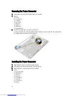
Page 32: ...sconnect the power connector cable and release the power connector cable from the routing channel b Remove the power connector from the computer Installing the Power Connector 1 Align the power connector to its position in the computer 2 Route the power connector cable through the routing channel 3 Connect the power connector cable to the system board 4 Install a display assembly b WLAN card c pal...

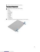
Page 33: ...he procedures in Before Working Inside Your Computer 2 Remove a battery b SD card c access panel d memory module e WLAN card f hard drive g optical drive h keyboard i palmrest j system board k display assembly 3 Press the hinge covers on the side Lift and remove the hinge covers from the computer 33 ...

Page 34: ...in place and snap it in place 2 Align the hinge covers on display assembly and snap the hinge covers on its place 3 Install a display assembly b system board c palmrest d keyboard e optical drive f hard drive g memory module h WLAN card i access panel j SD card k battery 4 Follow the procedures in After Working Inside Your Computer 34 ...

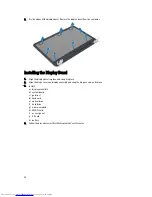
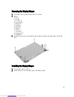
Page 35: ...hard drive g optical drive h keyboard i palmrest j system board k display assembly l display bezel 3 Remove the screws that secure the display hinges to the display assembly Lift the display hinges off the display panel Installing the Display Hinges 1 Place the display hinges on its place 2 Tighten the screws to secure the display hinges to the display assembly 35 ...

Page 36: ... card l battery 4 Follow the procedures in After Working Inside Your Computer Removing the Display Panel 1 Follow the procedures in Before Working Inside Your Computer 2 Remove a battery b SD card c access panel d memory module e WLAN card f hard drive g optical drive h keyboard i palmrest j system board k display assembly l display bezel m display hinges 36 ...

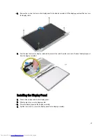
Page 37: ...res display cable and disconnect the cable from the connector Remove the display panel from the display assembly Installing the Display Panel 1 Connect the display cable to the display panel 2 Affix the tape to secure the display cable 3 Place the display panel on the display assembly 4 Tighten the screws to secure the display panel to the display assembly 37 ...

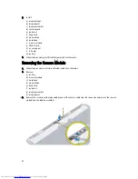
Page 38: ...e procedures in After Working Inside Your Computer Removing the Camera Module 1 Follow the procedures in Before Working Inside Your Computer 2 Remove a battery b memory module c hard drive d optical drive e keyboard f palmrest g display assembly h display bezel 3 Remove the screw peel the tape and disconnect the camera cable from the connector and remove the camera module from the display assembly...

Page 39: ...osition on the display assembly 3 Tighten the screw to secure the camera module to the display assembly 4 Affix the tape to the camera module 5 Install a display bezel b display assembly c palmrest d keyboard e optical drive f hard drive g memory module h battery 6 Follow the instructions in After Working Inside Your Computer 39 ...

Page 40: ...40 ...

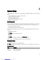
Page 41: ...ess System Setup by pressing F2 key Bring up the one time boot menu by pressing F12 key The one time boot menu displays the devices that you can boot from including the diagnostic option The boot menu options are Removable Drive if available STXXXX Drive NOTE XXX denotes the SATA drive number Optical Drive Diagnostics NOTE Choosing Diagnostics will display the ePSA diagnostics screen The boot sequ...

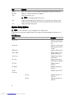
Page 42: ...er model The Main tab lists out the primary hardware features of the computer The table below defines the function of each option Table 2 Main Options Option Description System Time Allows you to reset the time on the computer s internal clock System Date Allows you to reset the date on the computer s internal calendar BIOS Version Displays the BIOS revision Product Name Displays the product name ...

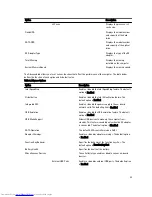
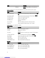
Page 43: ...e Intel Virtualization feature The default option is Enabled Integrated NIC Enable or disable the power supply to the on board network card The default option is Enabled USB Emulation Enable or disable the USB emulation feature The default option is Enabled USB Wake Support Allows USB devices to wake up the computer from standby This feature is enabled only when the AC adapter is connected The def...

Page 44: ...n your computer The Boot tab allows you to change the boot sequence Table 5 Boot Options Option Description Legacy Boot Allows you to set boot device sequence UEFI Boot Allows you to set boot device sequence Secure Boot Allows you to perform a secure boot to your computer The default option is Enabled Load Legacy Option ROM Allows you to load legacy option The default option is Disabled Boot List ...

Page 45: ... System drop down list select BIOS 9 Identify the latest BIOS file and click Download File You can also analyze which drivers need an update To do this for your product click Analyze System for Updates and follow the instructions on the screen 10 Select your preferred download method in the Please select your download method below window click Download File The File Download window appears 11 Clic...

Page 46: ...that you entered earlier and click OK 5 Select Setup Password type your system password and press Enter or Tab A message prompts you to re type the setup password 6 Type the setup password that you entered earlier and click OK 7 Press Esc and a message prompts you to save the changes 8 Press Y to save the changes The computer reboots Deleting or Changing an Existing System and or Setup Password En...

Page 47: ...6 Press Y to save the changes and exit from the System Setup The computer reboots 47 ...

Page 48: ...48 ...

Page 49: ...messages NOTE Some tests for specific devices require user interaction Always ensure that you are present at the computer terminal when the diagnostic tests are performed 1 Power on the computer 2 As the computer boots press the F12 key as the Dell logo appears 3 On the boot menu screen select the Diagnostics option The Enhanced Pre boot System Assessment window is displayed listing all devices de...

Page 50: ...he beep sound lasts 300 ms After each beep and each set of beeps the BIOS should detect if the user presses the power button If so BIOS will jump out from looping and execute the normal shutdown process and power system Code Cause and Troubleshooting Steps 1 BIOS ROM checksum in progress or failure System board failure covers BIOS corruption or ROM error 2 No RAM detected No memory detected 3 Chip...

Page 51: ...ROM error 2 Memory No memory RAM detected 3 Chipset Error North and South Bridge Chipset DMA IMR Timer Error Time Of Day Clock test failure Gate A20 failure Super I O chip failure Keyboard controller test failure System board failure 4 RAM Read Write failure Memory failure 5 Real time clock power fail CMOS battery failure 6 Video BIOS test failure Video card failure 7 CPU cache test failure Proces...

Page 52: ...52 ...

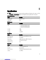
Page 53: ... Core i3 ULV 4th Generation Intel Core i5 ULV 4th Generation Intel Core i7 ULV 4th Generation L1 cache 64 KB L2 cache 256 KB L3 cache Up to 4 MB Table 9 Memory Feature Description Memory connector two internally accessible DDR3L connectors Memory capacity 2 GB and 4 GB Memory type 1600 MHz dual channel DDR3L configuration Minimum memory 2 GB 4 GB 6 GB and 8 GB Maximum memory 8 GB Table 10 Audio Fe...

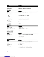
Page 54: ...0 64 bits Latitude 3540 128 bits Table 12 Camera Feature Description Camera resolution 0 92 megapixels Video resolution maximum 1280 x 720 HD at 30 fps maximum Diagonal viewing angle 66 Table 13 Communication Feature Description Network adapter 10 100 1000 Mbps Ethernet LAN on Motherboard LOM Wireless Wi fi 802 11 b g n bluetooth 4 0 Table 14 Ports and Connectors Feature Description Audio one head...

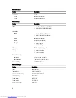
Page 55: ...inches Width 320 90 mm 12 63 inches 193 54 7 61 inches Diagonal 355 60 mm 14 00 inches 396 24 mm 15 60 inches Active area X Y 309 40 mm x 173 95 mm 12 18 inches x 6 85 inches 344 23 x 193 54 mm 13 55 inches x 7 61 inches Maximum resolution 1366 x 768 pixels Maximum brightness 200 nits Operating angle 0 closed to 135 0 closed to 140 Refresh rate 60 Hz Minimum viewing angles Horizontal 40 40 Vertica...

Page 56: ... 272 40 mm 10 72 inches Weight 4 cell 260 g 6 cell 360 g Life span 300 discharge charge cycle Voltage 14 80 VDC 4 cell 11 10 VDC 6 cell Temperature range Operating 0 C to 35 C 32 F to 95 F Non Operating 40 C to 65 C 40 F to 149 F Coin cell battery 3 V CR2032 lithium ion Table 19 AC Adapter Feature Description Type 65 W and 90 W Input voltage 100 VAC to 240 VAC Input current maximum 1 50 A 1 60 A 1...

Page 57: ...mm 14 80 inches Depth 245 00 mm 9 65 inches 259 00 mm 10 20 inches Weight minimum with 4 cell battery 2 00 kg 4 30 lb 2 20 kg 4 85 lb 2 20 kg 4 85 lb 2 50 kg 5 51 lb with 6 cell battery 2 10 kg 4 60 lb 2 35 kg 5 18 lb 2 35 kg 5 18 lb 2 65 kg 5 84 lb Table 21 Environmental Feature Description Temperature Operating 0 C to 35 C 32 F to 95 F Storage 40 C to 65 C 40 F to 149 F Relative humidity maximum...

Page 58: ...58 ...

Page 59: ...ed support and service options Availability varies by country and product and some services may not be available in your area To contact Dell for sales technical support or customer service issues 1 Visit dell com support 2 Select your support category 3 Verify your country or region in the Choose a Country Region drop down menu at the top of page 4 Select the appropriate service or support link b...

Reviews: