5.
Install:
a) display hinges
b) display bezel
c) display assembly
d) system board
e) palmrest
f) keyboard
g) optical drive
h) hard drive
i) memory module
j) WLAN card
k) access panel
l) SD card
m) battery
6.
Follow the procedures in
After Working Inside Your Computer
.
Removing the Camera Module
1.
Follow the procedures in
Before Working Inside Your Computer
.
2.
Remove:
a) battery
b) memory module
c) hard drive
d) optical drive
e) keyboard
f) palmrest
g) display assembly
h) display bezel
3.
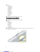
Remove the screw, peel the tape and disconnect the camera cable from the connector and remove the camera
module from the display assembly.
38
Summary of Contents for Latitude 3540
Page 1: ...Dell Latitude 3540 Owner s Manual Regulatory Model P28F Regulatory Type P28F004 ...
Page 8: ...8 ...
Page 40: ...40 ...
Page 47: ...6 Press Y to save the changes and exit from the System Setup The computer reboots 47 ...
Page 48: ...48 ...
Page 52: ...52 ...
Page 58: ...58 ...

