background image

Steps

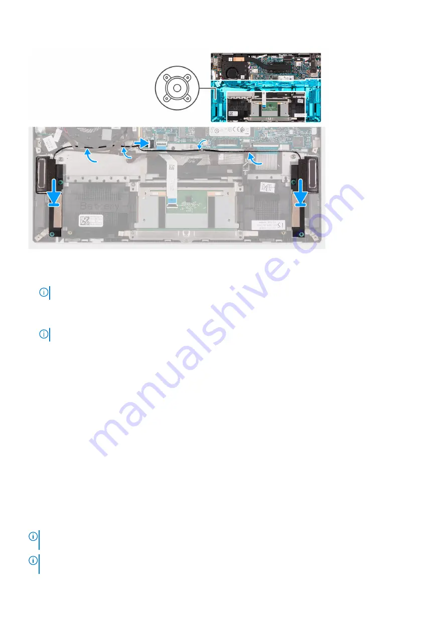
1. Using the alignment posts, place the right speaker on the palm-rest assembly.

NOTE:

 Ensure that the alignment posts are threaded through the rubber grommets on the speaker.

2. Route the speaker cable through the routing guides on the palm-rest assembly.
3. Using the alignment posts, place the left speaker on the palm-rest assembly.

NOTE:

 Ensure that the alignment posts are threaded through the rubber grommets on the speaker.

4. Route the speaker cable through the routing guides on the fan.
5. Connect the speaker cable to the system board.

Next steps

1. Install the 

base cover

.

2. Follow the procedure in 

After working inside your computer

.

Heat sink

Removing the heat sink

Prerequisites

1. Follow the procedure in 

Before working inside your computer

.

2. Remove the 

base cover

.

About this task

NOTE:

 The heat sink may become hot during normal operation. Allow sufficient time for the heat sink to cool before you

touch it.

NOTE:

 For maximum cooling of the processor, do not touch the heat transfer areas on the heat sink. The oils in your skin

can reduce the heat transfer capability of the thermal grease.

Removing and installing components

37

Summary of Contents for Inspiron 7306 2-in-1

Page 1: ...Inspiron 7306 2 in 1 Silver Service Manual Regulatory Model P124G Regulatory Type P124G002 July 2021 Rev A02 ...

Page 2: ...tial damage to hardware or loss of data and tells you how to avoid the problem WARNING A WARNING indicates a potential for property damage personal injury or death 2020 2021 Dell Inc or its subsidiaries All rights reserved Dell EMC and other trademarks are trademarks of Dell Inc or its subsidiaries Other trademarks may be trademarks of their respective owners ...

Page 3: ...te drive Intel Optane 17 Removing the M 2 2230 solid state drive 17 Installing the M 2 2230 solid state drive 18 Removing the M 2 2280 solid state drive Intel Optane H10 19 Installing the M 2 2280 solid state drive Intel Optane H10 20 Display assembly 21 Removing the display assembly 21 Installing the display assembly 23 Fans 26 Removing the fan 26 Installing the fan 26 Power adapter port 27 Remov...

Page 4: ...tering BIOS setup program 50 Navigation keys 50 Boot Sequence 50 One time boot menu 51 System setup options 51 Clearing CMOS settings 60 Clearing BIOS System Setup and System passwords 60 Updating the BIOS 60 Updating the BIOS in Windows 60 Updating the BIOS using the USB drive in Windows 61 Updating the BIOS from the F12 One Time boot menu 61 Chapter 5 Troubleshooting 63 Handling swollen Lithium ...

Page 5: ...r computer WARNING Before working inside your computer read the safety information that is shipped with your computer For more safety best practices see the Regulatory Compliance home page at www dell com regulatory_compliance WARNING Disconnect your computer from all power sources before opening the computer cover or panels After you finish working inside the computer replace all covers panels an...

Page 6: ...failures The high rate of intermittent failures means that most of the time when damage occurs it is not immediately recognizable The DIMM receives a static shock but the tracing is merely weakened and does not immediately produce outward symptoms related to the damage The weakened trace may take weeks or months to melt and in the meantime may cause degradation of memory integrity intermittent mem...

Page 7: ...kspace should also be free of insulators that can cause an ESD event On the work area insulators such as Styrofoam and other plastics should always be moved at least 12 inches or 30 centimeters away from sensitive parts before physically handling any hardware components ESD Packaging All ESD sensitive devices must be shipped and received in static safe packaging Metal static shielded bags are pref...

Page 8: ...nent is replaced NOTE Some computers have magnetic surfaces Ensure that the screws are not left attached to such surfaces when replacing a component NOTE Screw color may vary with the configuration ordered Table 1 Screw list Component Secured to Screw type Quantity Screw image Base cover Palm rest assembly M2x4 4 Battery Palm rest assembly M2x3 4 M 2 2230 mounting bracket System board M2x2 1 M 2 2...

Page 9: ...3 Power button with fingerprint reader Palm rest assembly M2x3 1 Power button bracket Palm rest assembly M2x3 1 Wireless card bracket Palm rest assembly M2x3 1 System board Palm rest assembly M2x2 3 Major components of Inspiron 7306 2 in 1 Silver The following image shows the major components of Inspiron 7306 2 in 1 Silver Removing and installing components 9 ...

Page 10: ...er adapter port 8 Palm rest assembly 9 Display assembly 10 I O board 11 Right speaker 12 System board 13 I O board cable 14 Coin cell battery 15 M 2 2280 solid state drive if applicable 16 Power button with fingerprint reader 17 Power button bracket 10 Removing and installing components ...

Page 11: ...les representative for purchase options NOTE Depending on the configuration ordered some components may not installed in your computer Base cover Removing the base cover Prerequisites 1 Follow the procedure in Before working inside your computer About this task The following image s indicate the location of the base cover and provides a visual representation of the removal procedure Removing and i...

Page 12: ...12 Removing and installing components ...

Page 13: ...Lift the base cover off the palm rest assembly 5 Using the pull tab disconnect the battery cable from the system board 6 Turn your computer over and press the power button for 15 seconds to drain the flea power Installing the base cover Prerequisites If you are replacing a component remove the existing component before performing the installation process About this task The following image s indic...

Page 14: ...Steps 1 Connect the battery cable to the system board 14 Removing and installing components ...

Page 15: ... of the battery Do not bend the battery Do not use tools of any kind to pry on or against the battery Ensure any screws during the servicing of this product are not lost or misplaced to prevent accidental puncture or damage to the battery and other system components If the battery gets stuck inside your computer as a result of swelling do not try to release it as puncturing bending or crushing a l...

Page 16: ...t the battery off the palm rest assembly Installing the battery Prerequisites If you are replacing a component remove the existing component before performing the installation process About this task The following image s indicate the location of the battery and provides a visual representation of the installation procedure 16 Removing and installing components ...

Page 17: ...the battery to the palm rest assembly Next steps 1 Install the base cover 2 Follow the procedure in After working inside your computer Solid state drive Intel Optane Removing the M 2 2230 solid state drive Prerequisites 1 Follow the procedure in Before working inside your computer 2 Remove the base cover About this task NOTE This procedure applies only to computers shipped with a M 2 2230 solid st...

Page 18: ...Installing the M 2 2230 solid state drive Prerequisites If you are replacing a component remove the existing component before performing the installation process About this task NOTE This procedure applies if you are installing a M 2 2230 solid state drive NOTE The M 2 card installed on your computer will depend on the configuration ordered Supported card configurations on the M 2 card slot M 2 22...

Page 19: ...side your computer Removing the M 2 2280 solid state drive Intel Optane H10 Prerequisites 1 Follow the procedure in Before working inside your computer 2 Remove the base cover About this task NOTE This procedure applies only to computers shipped with a M 2 2280 solid state drive or a M 2 2280 Intel Optane H10 installed NOTE The M 2 card installed on your computer will depend on the configuration o...

Page 20: ...ion process About this task NOTE This procedure applies if you are installing a M 2 2280 solid state drive or M 2 2280 Intel Optane H10 NOTE The M 2 card installed on your computer will depend on the configuration ordered Supported card configurations on the M 2 card slot M 2 2230 solid state drive 2230 mounting bracket M 2 2280 solid state drive M 2 2280 Intel Optane Memory H10 The following imag...

Page 21: ...id state drive Intel Optane to the system board Next steps 1 Install the base cover 2 Follow the procedure in After working inside your computer Display assembly Removing the display assembly Prerequisites 1 Follow the procedure in Before working inside your computer 2 Remove the base cover About this task The following image s indicate the location of the display assembly and provides a visual re...

Page 22: ...22 Removing and installing components ...

Page 23: ...nd palm rest assembly 7 Pry open the left display hinge 8 Remove the screw M2x5 that secures the right display hinge to the palm rest assembly 9 Remove the screw M2x3 5 that secures the right display hinge to the palm rest assembly and system board 10 Pry open the right display hinge 11 Lift and remove the palm rest assembly from the display assembly Installing the display assembly Prerequisites I...

Page 24: ...24 Removing and installing components ...

Page 25: ...lm rest assembly 5 Replace the screw M2x3 5 that secures the left display hinge to the I O board and palm rest assembly 6 Close the right display hinge NOTE Ensure that the screw holes on the right display hinge are aligned with the screw holes on the I O board and palm rest assembly 7 Replace the screw M2x5 that secures the right display hinge to the palm rest assembly 8 Replace the screw M2x3 5 ...

Page 26: ...base cover About this task The following image s indicate the location of the fan and provides a visual representation of the removal procedure Steps 1 Remove the antenna cables from the routing guides on the fan 2 Disconnect the fan cable from the system board 3 Remove the two screws M2x3 that secure the fan to the palm rest assembly 4 Lift the fan off the palm rest assembly Installing the fan Pr...

Page 27: ... the system board 4 Route the antenna cables through the routing guides on the fan Next steps 1 Install the base cover 2 Follow the procedure in After working inside your computer Power adapter port Removing the power adapter port Prerequisites 1 Follow the procedure in Before working inside your computer 2 Remove the base cover About this task The following image s indicate the location of the po...

Page 28: ...oard 5 Disconnect the power adapter port cable from the system board 6 Remove the screw M2x3 that secures the power adapter port to the palm rest assembly 7 Remove the power adapter port cable from the routing guide on the palm rest assembly 8 Lift the power adapter port along with its cable off the palm rest assembly Installing the power adapter port Prerequisites If you are replacing a component...

Page 29: ...lm rest assembly 4 Connect the power adapter port cable to the system board 5 Adhere the tape that secures the power adapter port cable to the system board 6 Close the right display hinge NOTE Ensure that the screw holes on the left display hinge are aligned with the screw holes on the system board and palm rest assembly 7 Replace the screw M2x5 that secures the right display hinge to the palm res...

Page 30: ...ell battery The following image s indicate the location of the coin cell battery and provides a visual representation of the removal procedure Steps 1 Peel the tape that secures the I O board cable latch to the I O board 2 Open the latch and disconnect the I O board cable from the I O board 3 Disconnect the coin cell battery cable from the I O board 4 Peel and lift the coin cell battery off the pa...

Page 31: ... O board and close the latch 4 Adhere the tape that secures the I O board cable latch to the I O board Next steps 1 Install the base cover 2 Follow the procedure in After working inside your computer I O board Removing the I O board Prerequisites 1 Follow the procedure in Before working inside your computer 2 Remove the base cover About this task The following image s indicate the location of the ...

Page 32: ...O board cable from the I O board 6 Disconnect the coin cell battery from the I O board 7 Remove the screw M2x2 that secures the I O board to the palm rest assembly 8 Lift the I O board from the palm rest assembly Installing the I O board Prerequisites If you are replacing a component remove the existing component before performing the installation process About this task The following image s indi...

Page 33: ...ard cable to the I O board and close the latch 7 Adhere the tape that secures the I O board cable latch to the I O board 8 Connect the coin cell battery cable to the I O board Next steps 1 Install the base cover 2 Follow the procedure in After working inside your computer Touchpad Removing the touchpad Prerequisites 1 Follow the procedure in Before working inside your computer 2 Remove the base co...

Page 34: ... Remove the two screws M2x2 that secure the touchpad to the palm rest assembly 6 Peel the tapes that secure the touchpad to the palm rest assembly 7 Lift the touchpad from the palm rest assembly Installing the touchpad Prerequisites If you are replacing a component remove the existing component before performing the installation process About this task The following image s indicate the location o...

Page 35: ...ws M1 6x2 that secure the touchpad bracket to the palm rest assembly 7 Adhere the mylar that covers the tape that secures the touchpad to the palm rest assembly Next steps 1 Install the battery 2 Install the base cover 3 Follow the procedure in After working inside your computer Speakers Removing the speakers Prerequisites 1 Follow the procedure in Before working inside your computer 2 Remove the ...

Page 36: ...he palm rest assembly 5 Lift both the speakers along with the speaker cable off the palm rest assembly Installing the speakers Prerequisites If you are replacing a component remove the existing component before performing the installation process About this task The following image s indicate the location of the speakers and provides a visual representation of the installation procedure 36 Removin...

Page 37: ... routing guides on the fan 5 Connect the speaker cable to the system board Next steps 1 Install the base cover 2 Follow the procedure in After working inside your computer Heat sink Removing the heat sink Prerequisites 1 Follow the procedure in Before working inside your computer 2 Remove the base cover About this task NOTE The heat sink may become hot during normal operation Allow sufficient time...

Page 38: ...oard Installing the heat sink Prerequisites If you are replacing a component remove the existing component before performing the installation process About this task NOTE If either the system board or the heat sink is replaced use the thermal grease provided in the kit to ensure that thermal conductivity is achieved The following image s indicate the location of the heat sink and provides a visual...

Page 39: ...ur computer Power button with fingerprint reader Removing the power button with fingerprint reader Prerequisites 1 Follow the procedure in Before working inside your computer 2 Remove the base cover 3 Remove the fan 4 Remove the I O board About this task The following image s indicate the location of the power button with fingerprint reader and provides a visual representation of the removal proce...

Page 40: ...Peel the tape that secures the power button with fingerprint reader cable to the palm rest assembly 6 Lift the power button and fingerprint reader and its cable off the palm rest assembly Installing the power button with fingerprint reader Prerequisites If you are replacing a component remove the existing component before performing the installation process About this task The following image s in...

Page 41: ...the palm rest assembly 6 Place the power button bracket on the power button with fingerprint reader 7 Replace the screw M2x3 that secures the power button bracket to the palm rest assembly Next steps 1 Install the I O board 2 Install the fan 3 Install the base cover 4 Follow the procedure in After working inside your computer System board Removing the system board Prerequisites 1 Follow the proced...

Page 42: ...About this task The following image s indicate the location of the system board and provides a visual representation of the removal procedure 42 Removing and installing components ...

Page 43: ...on the system board 12 Peel the tape that secures the I O board cable latch to the system board 13 Open the latch and disconnect the I O board cable from the system board 14 Disconnect the speaker cable from the system board 15 Open the latch and disconnect the touchpad cable from the system board 16 Open the latch and disconnect the keyboard backlight cable from the system board 17 Peel the Mylar...

Page 44: ...44 Removing and installing components ...

Page 45: ... to the system board and close the latch 7 Connect the power button board cable to the system board and close the latch 8 Connect the antenna cables to the wireless card on the system board The following table provides the antenna cable color scheme for the wireless card supported by your computer Table 2 Antenna cable color scheme Connectors on the wireless card Antenna cable color Silkscreen mar...

Page 46: ...s the right display hinge to the system board and palm rest assembly Next steps 1 Install the heat sink 2 Install the fan 3 Install the battery 4 Install the M 2 2230 solid state drive if applicable 5 Install the M 2 2280 solid state drive Intel Optane H10 if applicable 6 Install the base cover 7 Follow the procedure in After working inside your computer Palm rest and keyboard assembly Removing th...

Page 47: ...d assembly Prerequisites If you are replacing a component remove the existing component before performing the installation process About this task The following image s indicate the location of the palm rest and keyboard assembly and provides a visual representation of the installation procedure Removing and installing components 47 ...

Page 48: ... fingerprint reader 3 Install the speakers 4 Install the touchpad 5 Install the I O board 6 Install the coin cell battery 7 Install the power adapter port 8 Install the fan 9 Install the display assembly 10 Install the battery 11 Install the base cover 12 Follow the procedure in After working inside your computer 48 Removing and installing components ...

Page 49: ...rivers and downloads When troubleshooting downloading or installing drivers it is recommended that you read the Dell Knowledge Based article Drivers and Downloads FAQ 000123347 3 Drivers and downloads 49 ...

Page 50: ...k Turn on or restart your computer and press F2 immediately Navigation keys NOTE For most of the System Setup options changes that you make are recorded but do not take effect until you restart the system Table 3 Navigation keys Keys Navigation Up arrow Moves to the previous field Down arrow Moves to the next field Enter Selects a value in the selected field if applicable or follow the link in the...

Page 51: ... Drive if available SATA Hard Drive if available Diagnostics The boot sequence screen also displays the option to access the System Setup screen System setup options NOTE Depending on this computer and its installed devices the items that are listed in this section may or may not be displayed Table 4 System setup options System information menu Overview Inspiron 7306 2 in 1 BIOS Version Displays t...

Page 52: ...al computer memory installed Memory Available Displays the total computer memory available Memory Speed Displays the memory speed Memory Channel Mode Displays single or dual channel mode Memory Technology Displays the technology that is used for the memory DEVICES Panel Type Displays the Panel Type of the computer Video Controller Displays the integrate graphics information of the computer Video M...

Page 53: ... Enable Camera Enables or disables the camera By default Enable Camera is selected Audio Enable Audio Enables or disables all integrated audio controller Default ON Enable Microphone Enables or disables microphone By default Enable Microphone is selected Enable Internal Speaker Enables or disables internal speaker By default Enable Internal Speaker is selected USB Thunderbolt Configuration Enable ...

Page 54: ...Sets the screen brightness when the computer is running on battery power Default 50 Brightness on AC power Sets the screen brightness when the computer is running on AC power Default 100 Full Screen Logo When turned on the full screen logo is displayed if the image matches the screen resolution Default OFF Table 9 System setup options Connection menu Connection Wireless Device Enable WLAN Enable o...

Page 55: ...ystem power option will be blank if it was set to Sleep Lid Switch Enable Lid Switch Enable or disable the lid switch Default ON Power On Lid Open Enables the computer to power up from the off state whenever the lid is opened Default ON Intel Speed Shift Technology Enables or disables the Intel Speed Shift Technology support Setting this option to enable allows the operating system to select the a...

Page 56: ...ystem Password Enables the user to set change or delete the system password Password Configuration Upper Case Letter Enforces password restriction that the password must contain at least one upper case letter Default OFF Lower Case Letter Enforces password restriction that the password must contain at least one lower case letter Default OFF Digit Enforces password restriction that the password mus...

Page 57: ...orruption ME corruption or a hardware issue The recovery image must exist on an unencrypted partition on the drive BIOS Downgrade Allow BIOS Downgrade Controls flashing of the system firmware to previous revisions Default ON SupportAssist OS Recovery Enables or disables the boot flow for SupportAssist OS Recovery tool in the event of certain system error Default ON BIOSConnect Enables or disables ...

Page 58: ... define the timeout value for the keyboard backlight when an AC adapter is plugged into the system Default 1 minute Keyboard Backlight Timeout on Battery Enables the user to define the timeout value for the keyboard backlight when the system is operating only on battery power Default 1 minute Table 16 System setup options Pre boot Behavior menu Pre boot Behavior Adapter warnings Enable Adapter war...

Page 59: ...stem The default value is set to the maximum number of cores Default All Cores Intel SpeedStep Enable Intel SpeedStep Technology Enables or disables the Intel SpeedStep Technology to dynamically adjust processor voltage and core frequency decreasing average power consumption and heat production Default ON C State Control Enable C State Control Enables or disables the CPU s ability to enter and exi...
Page 60: ...uter follow the steps in Installing the base cover 5 Turn on your computer Clearing BIOS System Setup and System passwords About this task To clear the system or BIOS passwords contact Dell technical support as described at www dell com contactdell NOTE For information on how to reset Windows or application passwords refer to the documentation accompanying Windows or your application Updating the ...

Page 61: ... run the BIOS update file from Windows using a bootable USB drive or you can also update the BIOS from the F12 One Time boot menu on the computer Most of the Dell computers built after 2012 have this capability and you can confirm by booting your computer to the F12 One Time Boot Menu to see if BIOS FLASH UPDATE is listed as a boot option for your computer If the option is listed then the BIOS sup...

Page 62: ... the file and double click the flash target file and then click Submit 6 Click Update BIOS The computer restarts to flash the BIOS 7 The computer will restart after the BIOS update is completed 62 System setup ...

Page 63: ...o not apply pressure to the surface of the battery Do not bend the battery Do not use tools of any type to pry on or against the battery If a battery gets stuck in a device as a result of swelling do not try to free it as puncturing bending or crushing a battery can be dangerous Do not attempt to reassemble a damaged or swollen battery into a laptop Swollen batteries that are covered under warrant...

Page 64: ...the battery has more than 5 percent charge Amber Computer is running on battery and the battery has less than 5 percent charge Off Power adapter is connected and the battery is fully charged Computer is running on battery and the battery has more than 5 percent charge Computer is in sleep state hibernation or turned off The battery status light blinks amber along with beep codes indicating failure...

Page 65: ...ide at www dell com serviceabilitytools Click SupportAssist and then click SupportAssist OS Recovery Backup media and recovery options It is recommended to create a recovery drive to troubleshoot and fix problems that may occur with Windows Dell proposes multiple options for recovering Windows operating system on your Dell PC For more information see Dell Windows Backup Media and Recovery Options ...

Page 66: ...se cover NOTE Ensure that the battery is disconnected from the system board 3 Press and hold the power button for 15 seconds to drain the flea power 4 Follow the steps in Installing the base cover 5 Turn on your computer 66 Troubleshooting ...

Page 67: ... Service Tag or Express Service Code at www dell com support For more information on how to find the Service Tag for your computer see Locate the Service Tag on your computer Dell knowledge base articles for a variety of computer concerns 1 Go to www dell com support 2 On the menu bar at the top of the Support page select Support Knowledge Base 3 In the Search field on the Knowledge Base page type...

Reviews: