background image

Steps

1. Remove the two (M2.5x5) screws from the right hinge.
2. Pry open the right-display hinge at an angle of 90 degrees.
3. Disconnect the following cables from the system board:

a. I/O board Flexible Flat cable
b. Speaker cable
c. Hard drive Flexible Flat cable (for systems with 2.5-inch hard drive)
d. Touchpad Flexible Flat cable
e. Keyboard backlight Flexible Printed cable (for systems with backlit keyboard)
f. Keyboard Flexible Printed cable
g. Power adapter port cable
h. eDP cable

4. Remove the three (M2x3.5) screws and the single (M2x2) screw that secures the system board to the palm-rest assembly.
5. Carefully lift the system board away from the chassis.
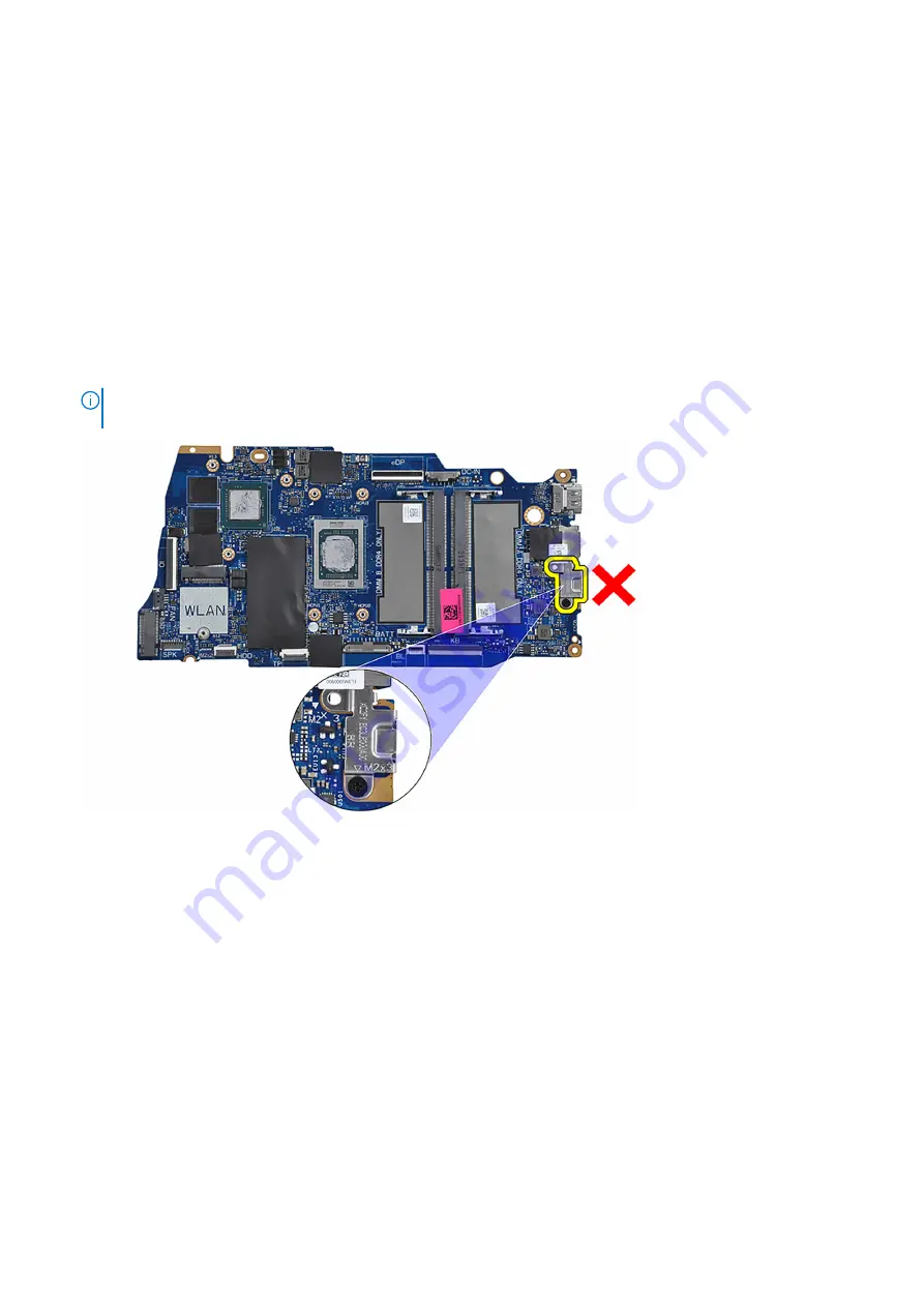
NOTE:

 For systems shipped with a USB Type-C port, do not remove the type-C bracket that is secured to the system

board.

Installing the system board

Prerequisites

If you are replacing a component, remove the existing component before performing the installation process.

About this task

The following image indicates the connectors on your system board.

88

Removing and installing components

Summary of Contents for Inspiron 15 3520

Page 1: ...Inspiron 15 3520 Service Manual Regulatory Model P112F Regulatory Type P112F001 P112F002 P112F007 P112F008 March 2022 Rev A00 ...

Page 2: ...ential damage to hardware or loss of data and tells you how to avoid the problem WARNING A WARNING indicates a potential for property damage personal injury or death 2022 Dell Inc or its subsidiaries All rights reserved Dell EMC and other trademarks are trademarks of Dell Inc or its subsidiaries Other trademarks may be trademarks of their respective owners ...

Page 3: ...y precautions 21 Removing the 3 cell battery 22 Installing the 3 cell battery 22 Removing the 4 cell battery 23 Installing the 4 cell battery 24 Disconnecting the battery cable 25 Connecting the battery cable 26 M 2 solid state drive 27 Removing the M 2 2230 solid state drive 27 Installing the M 2 2230 solid state drive 28 Removing the M 2 2280 solid state drive 29 Installing the M 2 2280 solid st...

Page 4: ...y assembly 58 Hinge caps 61 Removing the hinge caps 61 Installing the hinge caps 63 Display bezel 64 Removing the display bezel 64 Installing the display bezel 65 Hinges 66 Removing the hinges 66 Installing the hinges 68 Display panel 70 Removing the display panel 70 Installing the display panel 73 Camera module 77 Removing the camera module 77 Installing the camera module 78 eDP cable 79 Removing...

Page 5: ...asswords 103 Updating the BIOS 104 Updating the BIOS in Windows 104 Updating the BIOS using the USB drive in Windows 104 Updating the BIOS in Linux and Ubuntu 104 Updating the BIOS from the F12 One Time boot menu 104 Chapter 5 Troubleshooting 106 Handling swollen Lithium ion batteries 106 Locate the Service Tag or Express Service Code of your Dell computer 106 System diagnostic lights 107 SupportA...

Page 6: ...atory_compliance WARNING Disconnect your computer from all power sources before opening the computer cover or panels After you finish working inside the computer replace all covers panels and screws before connecting your computer to an electrical outlet CAUTION To avoid damaging the computer ensure that the work surface is flat dry and clean CAUTION To avoid damaging the components and cards hand...

Page 7: ...ent also called latent or walking wounded failure Perform the following steps to prevent ESD damage Use a wired ESD wrist strap that is properly grounded The use of wireless anti static straps is no longer allowed they do not provide adequate protection Touching the chassis before handling parts does not ensure adequate ESD protection on parts with increased sensitivity to ESD damage Handle all st...

Page 8: ...part arrived in The ESD bag should be folded over and taped shut and all the same foam packing material should be used in the original box that the new part arrived in ESD sensitive devices should be removed from packaging only at an ESD protected work surface and parts should never be placed on top of the ESD bag because only the inside of the bag is shielded Always place parts in your hand on th...

Page 9: ...e that no stray screws remain inside your computer 2 Connect any external devices peripherals or cables you removed before working on your computer 3 Replace any media cards discs or any other parts that you removed before working on your computer 4 Connect your computer and all attached devices to their electrical outlets 5 Turn on your computer Working inside your computer 9 ...

Page 10: ...s to ensure that the correct number of screws and correct screw type is restored when the component is replaced NOTE Some computers have magnetic surfaces Ensure that the screws are not left attached to such surfaces when replacing a component NOTE Screw color may vary with the configuration ordered Table 1 Screw list Component Screw type Quantity Screw image Base cover M2x5 Captive screw 6 2 3 ce...

Page 11: ... OD 5 1 Power button with optional fingerprint reader M2 5x5 M2x2 OD 5 2 1 Display assembly M2 5x5 4 System board M2x3 5 M2x2 OD 5 3 1 USB Type C bracket M2x3 5 2 Touchpad Touchpad bracket M2x2 OD 5 Big Head M2x2 OD 5 Big Head 2 3 Major components of Inspiron 15 3520 The following image shows the major components of Inspiron 15 3520 Removing and installing components 11 ...

Page 12: ...12 Removing and installing components ...

Page 13: ...d 16 Heat sink 17 Fan 18 I O board FFC 19 Hard disk drive Secure Digital SD Card Removing the Secure Digital card Prerequisites 1 Follow the procedure in Before working inside your computer About this task Steps 1 Push the secure digital card to release it from the card slot 2 Slide the secure digital card out of the computer Installing the Secure Digital card Prerequisites If you are replacing a ...

Page 14: ...over Prerequisites 1 Follow the procedure in Before working inside your computer 2 Remove the SD card About this task NOTE Before removing the base cover ensure that there is no SD card installed in the SD card slot on your computer The following images indicate the location of the base cover and provide a visual representation of the removal procedure 14 Removing and installing components ...

Page 15: ...Removing and installing components 15 ...

Page 16: ...16 Removing and installing components ...

Page 17: ...Removing and installing components 17 ...

Page 18: ...nges 4 Lift the base cover off the palm rest and keyboard assembly 5 Disconnect the battery cable from the system board 6 Press and hold the power button for five seconds to ground the computer and drain the flea power Installing the base cover Prerequisites If you are replacing a component remove the existing component before performing the installation process About this task The following image...

Page 19: ...Removing and installing components 19 ...

Page 20: ...20 Removing and installing components ...

Page 21: ... inside your computer Battery Lithium ion battery precautions CAUTION Exercise caution when handling Lithium ion batteries Discharge the battery completely before removing it Disconnect the AC power adapter from the system and operate the computer solely on battery power the battery is fully discharged when the computer no longer turns on when the power button is pressed Do not crush drop mutilate...

Page 22: ...the location of the 3 cell battery and provides a visual representation of the removal procedure Steps 1 Disconnect the battery cable from the system board if applicable 2 Remove the three M2x3 screws that secure the battery to the palm rest and keyboard assembly 3 Remove the battery from the palm rest and keyboard assembly Installing the 3 cell battery Prerequisites If you are replacing a compone...

Page 23: ... removal procedure Steps 1 Disconnect the battery cable from the system board if applicable 2 Remove the four M2x3 screws that secure the battery to the palm rest and keyboard assembly 3 Remove the battery from the palm rest and keyboard assembly NOTE When replacing the 4 cell battery use a scribe push upward through the bottom left screw hole to remove the battery rubber stopper and transfer it t...

Page 24: ...component remove the existing component before performing the installation process About this task The following image indicates the location of the 4 cell battery and provides a visual representation of the installation procedure 24 Removing and installing components ...

Page 25: ...ward through the bottom left screw hole to remove the battery rubber stopper and transfer it to the new replacement 4 cell battery Next steps 1 Install the base cover 2 Install the SD card 3 Follow the procedure in After working inside your computer Disconnecting the battery cable Prerequisites 1 Follow the procedure in Before working inside your computer 2 Remove the SD card 3 Remove the base cov...

Page 26: ...the battery cable Prerequisites If you are replacing a component remove the existing component before performing the installation process About this task The following images indicate the location of the battery cable and provide a visual representation of the installation procedure 26 Removing and installing components ...

Page 27: ... in Before working inside your computer 2 Remove the SD card 3 Remove the base cover About this task NOTE This procedure applies only to computers shipped with an M 2 2230 solid state drive installed NOTE The M 2 card installed on your computer depends on the configuration ordered Supported card configurations on the M 2 card slot M 2 2230 solid state drive M 2 2280 solid state drive The following...

Page 28: ...ing a component remove the existing component before performing the installation process About this task NOTE This procedure applies if you are installing a M 2 2230 solid state drive NOTE The M 2 card installed on your computer depends on the configuration ordered Supported card configurations on the M 2 card slot M 2 2230 solid state drive M 2 2280 solid state drive The following images indicate...

Page 29: ...l the SD card 3 Follow the procedure in After working inside your computer Removing the M 2 2280 solid state drive Prerequisites 1 Follow the procedure in Before working inside your computer 2 Remove the SD card 3 Remove the base cover About this task NOTE This procedure applies only to computers shipped with a M 2 2280 solid state drive installed NOTE The M 2 card installed on your computer depen...

Page 30: ...ing a component remove the existing component before performing the installation process About this task NOTE This procedure applies if you are installing a M 2 2280 solid state drive NOTE The M 2 card installed on your computer depends on the configuration ordered Supported card configurations on the M 2 card slot M 2 2230 solid state drive M 2 2280 solid state drive The following images indicate...

Page 31: ...the M2x2 screw that secures the M 2 thermal plate and the M 2 solid state drive to the palm rest and keyboard assembly Next steps 1 Install the base cover 2 Install the SD card 3 Follow the procedure in After working inside your computer Wireless card Removing the wireless card Prerequisites 1 Follow the procedure in Before working inside your computer 2 Remove the SD card 3 Remove the base cover ...

Page 32: ...e wireless card 3 Disconnect the antenna cables from the wireless card 4 Slide and remove the wireless card from the WLAN slot on the system board Installing the wireless card Prerequisites If you are replacing a component remove the existing component before performing the installation process 32 Removing and installing components ...

Page 33: ...ct the antenna cables to the wireless card The following table provides the antenna cable color scheme for the wireless card supported by your computer Table 2 Antenna cable color scheme Connectors on the wireless card Antenna cable color Silkscreen marking Main White MAIN white triangle Auxiliary Black AUX black triangle Removing and installing components 33 ...

Page 34: ... Remove the SD card 3 Remove the base cover About this task The following images indicate the location of the Input Output board and provide a visual representation of the removal procedure Steps 1 Remove the two M2 5x5 screws that secure the display hinge to the palm rest and keyboard assembly 2 Lift the hinge up to access the I O board 3 Open the latch and disconnect the I O board cable from the...

Page 35: ... the I O board to the screw holes on the palm rest and keyboard assembly 3 Replace the three M2x3 5 screws that secure the I O board to the palm rest and keyboard assembly 4 Connect the fingerprint reader board cable to the connector on the I O board and close the latch if applicable 5 Connect the I O board power cable to the connector on the I O board and close the latch 6 Close the hinge and rep...

Page 36: ... computer 2 Remove the SD card 3 Remove the base cover 4 Remove the fan About this task The following image indicates the location of the Input Output daughter board FFC and provides a visual representation of the removal procedure in an aluminum chassis For systems shipped with a plastic chassis 36 Removing and installing components ...

Page 37: ...ghter board cable underneath the wireless card antenna cables and lift off the palm rest and keyboard assembly Installing the Input Output daughter board FFC Prerequisites If you are replacing a component remove the existing component before performing the installation process About this task The following images indicate the location of the I O daughter board FFC and provide a visual representati...

Page 38: ... daughter board FFC on the palm rest and keyboard assembly For systems shipped with a plastic chassis slide and place the I O daughter board FFC underneath the wireless card antenna cables on the palm rest and keyboard assembly 38 Removing and installing components ...

Page 39: ...SD card 4 Follow the procedure in After working inside your computer Hard drive assembly Removing the hard drive Prerequisites 1 Follow the procedure in Before working inside your computer 2 Remove the SD card 3 Remove the base cover About this task The following images indicate the location of the hard drive and provide a visual representation of the removal procedure Removing and installing comp...

Page 40: ...hard drive assembly 5 Remove the four M3x3 screws that secure the hard drive to the hard drive bracket 6 Slide and remove the hard drive from the hard drive bracket Installing the hard drive Prerequisites If you are replacing a component remove the existing component before performing the installation process About this task The following images indicate the location of the hard drive assembly and...

Page 41: ...e the hard drive assembly on the palm rest and keyboard assembly 6 Align the screw holes on the hard drive assembly to the screw holes on the palm rest and keyboard assembly 7 Replace the four M2x3 5 screws that secure the hard drive assembly to the palm rest and keyboard assembly 8 Connect the hard drive cable to the connector on the system board Next steps 1 Install the base cover 2 Install the ...

Page 42: ...s and provide a visual representation of the removal procedure Steps 1 Using your fingertips carefully spread apart the securing clips on each end of the memory module slot until the memory module pops up 2 Remove the memory module from the memory module slot on the system board NOTE Your computer may have up to two memory modules installed Repeat steps 1 to 2 if there is a second memory module in...

Page 43: ...he notch on the memory module with the tab on the memory module slot on the system board 2 Slide the memory module into the memory module slot on the system board 3 Press down on the memory module until the securing clips click locking the memory module in place NOTE Repeat steps 1 to 3 if there is a second memory module to be installed into your computer Next steps 1 Install the base cover 2 Inst...

Page 44: ...presentation of the removal procedure Steps 1 Disconnect the speaker cable from the system board 2 Unroute the speaker cable from the routing guides on the palm rest and keyboard assembly 3 Lift the speakers along with its cable from the palm rest and keyboard assembly Installing the speakers Prerequisites If you are replacing a component remove the existing component before performing the install...

Page 45: ...ugh the rubber grommets on the speaker 2 Route the speaker cable through the routing guides on the palm rest and keyboard assembly 3 Connect the speaker cable to the system board Next steps 1 Install the base cover 2 Install the SD card 3 Follow the procedure in After working inside your computer Heat sink Removing the heat sink Prerequisites 1 Follow the procedure in Before working inside your co...

Page 46: ...to the system board NOTE Loosen the captive screws in the reverse sequential order mentioned on the heat sink 4 3 2 1 NOTE The number of screws varies depending on the configuration ordered 2 Lift the heat sink from the system board Installing the heat sink Prerequisites If you are replacing a component remove the existing component before performing the installation process About this task NOTE I...

Page 47: ...ng on the configuration ordered Next steps 1 Install the base cover 2 Install the SD card 3 Follow the procedure in After working inside your computer Fan Removing the fan Prerequisites 1 Follow the procedure in Before working inside your computer 2 Remove the SD card 3 Remove the base cover About this task The following images indicate the location of the fan and provide a visual representation o...

Page 48: ...an from the palm rest and keyboard assembly Installing the fan Prerequisites If you are replacing a component remove the existing component before performing the installation process About this task The following images indicate the location of the fan and provide a visual representation of the installation procedure 48 Removing and installing components ...

Page 49: ...fan to the palm rest and keyboard assembly 4 Connect the fan cable to the connector on the system board Next steps 1 Install the base cover 2 Install the SD card 3 Follow the procedure in After working inside your computer Power button board Removing the power button Prerequisites 1 Follow the procedure in Before working inside your computer 2 Remove the SD card Removing and installing components ...

Page 50: ...he single M2x2 screw securing the power button to the palm rest and keyboard assembly 2 Remove the power button from the computer Installing the power button Prerequisites If you are replacing a component remove the existing component before performing the installation procedure About this task The following images indicate the location of the power button and provide a visual representation of th...

Page 51: ...nstall the I O board 4 Install the base cover 5 Install the SD card 6 Follow the procedure in After working inside your computer Power button with fingerprint reader Removing the power button with optional fingerprint reader Prerequisites 1 Follow the procedure in Before working inside your computer 2 Remove the SD card 3 Remove the base cover 4 Remove the wireless card 5 Remove the I O board 6 Re...

Page 52: ...t and keyboard assembly 4 Peel the fingerprint reader Flexible Flat cable from the palm rest and keyboard assembly 5 Lift the power button with fingerprint reader along with its cable off the palm rest and keyboard assembly Installing the power button with optional fingerprint reader Prerequisites If you are replacing a component remove the existing component before performing the installation pro...

Page 53: ...ign the fingerprint reader Flexible Flat cable to the mark at the right of the power button and align the white line on the Flexible Flat cable to the mark on the palm rest and keyboard assembly 4 Close the display hinge 5 Replace the two M2 5x5 screws that secure the display hinge to the palm rest and keyboard assembly Next steps 1 Install the display assembly 2 Install the wireless card 3 Instal...

Page 54: ...Before working inside your computer 2 Remove the SD card 3 Remove the base cover 4 Remove the wireless card About this task The following images indicate the location of the display assembly and provide a visual representation of the removal procedure 54 Removing and installing components ...

Page 55: ...Removing and installing components 55 ...

Page 56: ...56 Removing and installing components ...

Page 57: ...cable from the system board for systems with aluminum chassis 3 Unroute the WLAN antenna cables from the routing guides on the palm rest and keyboard assembly for systems with plastic chassis NOTE The procedure and images documented is for systems shipped with a plastic chassis The same procedure is also applicable for system shipped with aluminum chassis with the exception of the WLAN antenna cab...

Page 58: ...face 5 Remove the display assembly from the palm rest and keyboard assembly Installing the display assembly Prerequisites If you are replacing a component remove the existing component before performing the installation process About this task The following images indicate the location of the display assembly and provide a visual representation of the installation procedure 58 Removing and install...

Page 59: ...Removing and installing components 59 ...

Page 60: ...the display hinges with the screw holes on the palm rest and keyboard assembly 3 Replace the four M2 5x5 screws that secure the display hinges to the palm rest and keyboard assembly 4 Route the WLAN antenna cables through the routing guides on the palm rest and keyboard assembly Adhere the tape to the heat sink and fan to secure the cables in place 60 Removing and installing components ...

Page 61: ... hinge caps Prerequisites NOTE This procedure is applicable for systems with plastic chassis 1 Follow the procedure in Before working inside your computer 2 Remove the SD card 3 Remove the base cover 4 Remove the wireless card 5 Remove the display assembly About this task The following images indicate the location of the hinge caps and provide a visual representation of the installation procedure ...

Page 62: ... hinge cap in the center 2 Using a plastic scribe pry the inner side of the left hinge cap and remove it from the left hinge 3 Pinch the right hinge cap in the center 4 Using a plastic scribe pry the inner side of the right hinge cap and remove it from the right hinge 62 Removing and installing components ...

Page 63: ...onent before performing the installation procedure NOTE This procedure is applicable for systems with plastic chassis About this task The following images indicate the location of the hinge caps and provide a visual representation of the installation procedure Removing and installing components 63 ...

Page 64: ... card 5 Follow the procedure in After working inside your computer Display bezel Removing the display bezel Prerequisites NOTE This procedure is applicable for systems with plastic chassis 1 Follow the procedure in Before working inside your computer 2 Remove the SD card 3 Remove the base cover 4 Remove the wireless card 5 Remove the display assembly 6 Remove the hinge caps About this task The fol...

Page 65: ...ner edge at the bottom side of the display assembly 5 Lift and remove the display bezel from the display assembly Installing the display bezel Prerequisites If you are replacing a component remove the existing component before performing the installation procedure NOTE This procedure is applicable for systems with plastic chassis About this task The following image indicates the location of the di...

Page 66: ... 3 Install the wireless card 4 Install the base cover 5 Install the SD card 6 Follow the procedure in After working inside your computer Hinges Removing the hinges Prerequisites NOTE This procedure is applicable for systems with a plastic chassis only 1 Follow the procedure in Before working inside your computer 2 Remove the SD card 3 Remove the base cover 66 Removing and installing components ...

Page 67: ...play assembly 6 Remove the hinge caps 7 Remove the display bezel About this task The following images indicate the location of the hinge caps and provide a visual representation of the installation procedure Removing and installing components 67 ...

Page 68: ... Lift and remove the right hinge from the display assembly Installing the hinges Prerequisites If you are replacing a component remove the existing component before performing the installation procedure About this task The following images indicate the location of the hinges and provide a visual representation of the installation procedure 68 Removing and installing components ...

Page 69: ...8 screws to secure the hinge to the display panel and back cover 3 Align and place the right hinge on the display assembly 4 Install the three M2 5x3 8 screws to secure the hinge to the display panel and back cover Next steps 1 Install the display bezel Removing and installing components 69 ...

Page 70: ...is applicable for systems with a plastic chassis only 1 Follow the procedure in Before working inside your computer 2 Remove the SD card 3 Remove the base cover 4 Remove the wireless card 5 Remove the display assembly 6 Remove the hinge caps 7 Remove the display bezel 8 Remove the hinges About this task The following images indicate the location of the display panel and provide a visual representa...

Page 71: ...Removing and installing components 71 ...

Page 72: ...72 Removing and installing components ...

Page 73: ...isplay panel NOTE Ensure that the panel has a clean and smooth surface to rest on to prevent damage 5 Disconnect the display cable from the display panel assembly and lift the display panel away from the system NOTE Do not remove the metal brackets from the panel Installing the display panel Prerequisites If you are replacing a component remove the existing component before performing the installa...

Page 74: ...74 Removing and installing components ...

Page 75: ...Removing and installing components 75 ...

Page 76: ...e the display panel on the display assembly 5 Place the display bezel on the display assembly 6 Align the tabs on the display bezel to the slots on the display assembly 7 Press down on the display bezel and snap the display bezel in place Next steps 1 Install the hinges 2 Install the hinge caps 3 Install the display assembly 4 Install the wireless card 5 Install the base cover 6 Install the SD car...

Page 77: ...y bezel 8 Remove the hinges 9 Remove the display panel About this task The following images indicate the location of the camera module and provide a visual representation of the removal procedure Steps 1 Using the pull tab disconnect the camera cable from the camera module 2 Using a plastic scribe pry the camera module from the display assembly NOTE Start prying the camera module in a sequential o...

Page 78: ... of the installation procedure Steps 1 Adhere the camera module in its slot on the display assembly 2 Connect the camera cable to the camera module Next steps 1 Install the display panel 2 Install the hinges 3 Install the display bezel 4 Install the hinge caps 5 Install the display assembly 6 Install the wireless card 7 Install the base cover 8 Install the SD card 9 Follow the procedure in After w...

Page 79: ...ur computer 2 Remove the SD card 3 Remove the base cover 4 Remove the wireless card 5 Remove the display assembly 6 Remove the hinge caps 7 Remove the display bezel 8 Remove the hinges 9 Remove the display panel About this task The following image indicates the location of the eDP cable and provides a visual representation of the removal procedure Removing and installing components 79 ...

Page 80: ...er Installing the eDP cable About this task NOTE The eDP cable installation procedure is applicable only for systems with plastic chassis The following image indicates the location of the eDP cable and provides a visual representation of the installation procedure 80 Removing and installing components ...

Page 81: ...t the eDP cable to the camera Next steps 1 Install the display panel 2 Install the hinges 3 Install the display bezel 4 Install the hinge caps 5 Install the display assembly 6 Install the wireless card 7 Install the base cover 8 Install the SD card Removing and installing components 81 ...

Page 82: ...card 5 Remove the display assembly 6 Remove the hinge caps 7 Remove the display bezel 8 Remove the hinges 9 Remove the display panel 10 Remove the camera module 11 Remove the eDP cable NOTE The display cover and antenna assembly cannot be further disassembled If the WLAN antennas are malfunctioning and needs replacement replace the entire display cover and antenna assembly About this task The foll...

Page 83: ... Follow the procedure in Before working inside your computer 2 Remove the SD card 3 Remove the base cover 4 Remove the 3 cell battery or 4 cell battery whichever applicable About this task The following images indicate the location of the touchpad and provide a visual representation of the removal procedure Removing and installing components 83 ...

Page 84: ...rom the connector on the system board 5 Remove the two screws M2x2 that secure the touchpad to the palm rest and keyboard assembly 6 Lift the touchpad from the palm rest and keyboard assembly Installing the touchpad Prerequisites If you are replacing a component remove the existing component before performing the installation process About this task The following images indicate the location of th...

Page 85: ...e screw holes on the touchpad bracket to the screw holes on the palm rest and keyboard assembly 7 Replace the three M2x2 screws that secure the touchpad bracket to the palm rest and keyboard assembly 8 Connect the hard drive cable to the connector on the system board Next steps 1 Install the 3 cell battery or 4 cell battery whichever applicable 2 Install the base cover 3 Install the SD card 4 Foll...

Page 86: ...llowing image indicates the connectors on your system board 1 Fan connector 2 I O board FFC connector 3 eDP connector 4 DC in port connector 5 Keyboard FFC connector 6 Keyboard backlight FFC connector 7 Battery connector 8 Memory modules 9 Touchpad FFC connector 10 Hard drive FFC connector 11 Wireless connector 12 Speaker cable connector 13 Solid state drive connector The following images indicate...

Page 87: ...Removing and installing components 87 ...

Page 88: ...lexible Printed cable g Power adapter port cable h eDP cable 4 Remove the three M2x3 5 screws and the single M2x2 screw that secures the system board to the palm rest assembly 5 Carefully lift the system board away from the chassis NOTE For systems shipped with a USB Type C port do not remove the type C bracket that is secured to the system board Installing the system board Prerequisites If you ar...

Page 89: ...or 7 Battery connector 8 Memory modules 9 Touchpad FFC connector 10 Hard drive FFC connector 11 Wireless connector 12 Speaker cable connector 13 Solid state drive connector The following images indicate the location of the system board and provide a visual representation of the installation procedure Removing and installing components 89 ...

Page 90: ...90 Removing and installing components ...

Page 91: ... holes on the right display hinge with the screw holes on the system board 7 Replace the two M2 5x5 screws to secure it to the palm rest assembly Next steps 1 Install the display assembly 2 Install the heat sink 3 Install the fan 4 Install the wireless card 5 Install the memory modules 6 Install the M 2 2230 solid state drive or M 2 2280 solid state drive whichever applicable 7 Install the 3 cell ...

Page 92: ...er port from its slot on the palm rest and keyboard assembly Installing the power adapter port Prerequisites If you are replacing a component remove the existing component before performing the installation process About this task The following images indicate the location of the power adapter port and provide a visual representation of the installation procedure 92 Removing and installing compone...

Page 93: ...stall the base cover 3 Install the SD card 4 Follow the procedure in After working inside your computer Palm rest and keyboard assembly Removing the palm rest and keyboard assembly Prerequisites 1 Follow the procedure in Before working inside your computer 2 Remove the SD card 3 Remove the base cover 4 Remove the 3 cell battery or 4 cell battery whichever applicable 5 Remove the M 2 2230 solid sta...

Page 94: ...NOTE The system board can be removed along with the heat sink About this task NOTE The following image shows the palm rest for aluminum chassis which has WLAN antennas attached to it The following image indicates the location of the palm rest and keyboard assembly and provides a visual representation of the removal procedure NOTE For systems with an aluminum chassis both the left and right RF meta...

Page 95: ...d assembly Prerequisites If you are replacing a component remove the existing component before performing the installation process About this task The following image indicates the location of the palmrest and keyboard assembly and provides a visual representation of the installation procedure Removing and installing components 95 ...

Page 96: ...y 5 Install the touchpad 6 Install the hard drive assembly 7 Install the I O board 8 Install the heat sink 9 Install the fan 10 Install the speakers 11 Install the wireless card 12 Install the memory modules 13 Install the M 2 2230 solid state drive or M 2 2280 solid state drive whichever applicable 14 Install the 3 cell battery or 4 cell battery whichever applicable 15 Install the base cover 16 I...

Page 97: ...rivers and downloads When troubleshooting downloading or installing drivers it is recommended that you read the Dell Knowledge Based article Drivers and Downloads FAQ 000123347 3 Drivers and downloads 97 ...

Page 98: ...ling base devices Entering BIOS setup program About this task Turn on or restart your computer and press F2 immediately Navigation keys NOTE For most of the System Setup options changes that you make are recorded but do not take effect until you restart the system Table 3 Navigation keys Keys Navigation Up arrow Moves to the previous field Down arrow Moves to the next field Enter Selects a value i...

Page 99: ...r Asset Tag Displays the asset tag of your computer CPU Type Displays the processor type CPU Speed Displays the processor speed CPU ID Displays the processor identification code CPU Cache L1 Cache Displays the processor L1 cache size L2 Cache Displays the processor L2 cache size L3 Cache Displays the processor L3 cache size First HDD Displays the type of hard drive installed M 2 PCIe SSD Displays ...

Page 100: ...vior Default Multimedia key Keyboard Illumination Selects the operating mode of the keyboard illumination feature Default Dim Keyboard Backlight with AC Selects the timeout value for the keyboard backlight when an AC adapter is plugged into the computer Default 1 minute Keyboard Backlight with Battery Selects the timeout value for the keyboard backlight when the computer is running on battery powe...

Page 101: ...set Default Not Set System Password Status Displays if the system password is clear or set Default Not Set Asset Tag Set your system s Asset Tag Admin Password Allows you to set the administrator password The administrator password controls access to the system setup utility System Password Allows you to set the system password The system password controls access to the computer at boot HDD Passwo...

Page 102: ...ges Save Change Without Exit Allows you to save your changes without exiting the BIOS setup Exit Discarding Changes Allows you to exit the BIOS setup without saving the changes Load Optimal Defaults Allows you to restore default values for all system setup options Discard Changes Allows you to load previous values for all system setup options System and setup password Table 9 System and setup pass...

Page 103: ...the System Setup before attempting to delete or change the existing System and or Setup password You cannot delete or change an existing System or Setup password if the Password Status is Locked About this task To enter the System Setup press F12 immediately after a power on or reboot Steps 1 In the System BIOS or System Setup screen select System Security and press Enter The System Security scree...

Page 104: ... BIOS using the USB drive in Windows Steps 1 Follow the procedure from step 1 to step 6 in Updating the BIOS in Windows to download the latest BIOS setup program file 2 Create a bootable USB drive For more information see the knowledge base article 000145519 at www dell com support 3 Copy the BIOS setup program file to the bootable USB drive 4 Connect the bootable USB drive to the computer that ne...

Page 105: ... the USB drive AC power adapter that is connected to the computer Functional computer battery to flash the BIOS Perform the following steps to perform the BIOS update flash process from the F12 menu CAUTION Do not turn off the computer during the BIOS update process The computer may not boot if you turn off your computer Steps 1 From a turn off state insert the USB drive where you copied the flash...

Page 106: ...cks and cells Do not apply pressure to the surface of the battery Do not bend the battery Do not use tools of any type to pry on or against the battery If a battery gets stuck in a device as a result of swelling do not try to free it as puncturing bending or crushing a battery can be dangerous Do not attempt to reassemble a damaged or swollen battery into a laptop Swollen batteries that are covere...

Page 107: ... memory module 2 5 Invalid memory installed Reset and swap memory modules among the slots If problem persists replace the memory module 2 6 System board Chipset Error Replace the system board 2 7 LCD failure SBIOS message Replace the LCD module 2 8 LCD failure EC detection of power rail failure Replace the system board 3 1 CMOS battery failure Reset the main battery connection If problem persists ...

Page 108: ...tAssist diagnostics provides a set of options for particular devices or device groups It allows you to Run tests automatically or in an interactive mode Repeat tests Display or save test results Run thorough tests to introduce additional test options and provide extra information about the failed device s View status messages that indicate if the tests are completed successfully View error message...

Page 109: ...dust particles on the surface of the screen 4 Press and hold D key and Power on the laptop to enter LCD built in self test BIST mode Continue to hold the D key until the system boots up 5 The screen will display solid colors and change colors on the entire screen to white black red green and blue twice 6 Then it will display the colors white black and red 7 Carefully inspect the screen for abnorma...

Page 110: ...tery is removed For your safety and to protect the sensitive electronic components in your computer you are requested to drain residual flea power before removing or replacing any components in your computer Draining residual flea power also known as a performing a hard reset is also a common troubleshooting step if your computer does not power on or boot into the operating system To drain residua...

Page 111: ...Service Tag or Express Service Code at www dell com support For more information on how to find the Service Tag for your computer see Locate the Service Tag on your computer Dell knowledge base articles for a variety of computer concerns 1 Go to www dell com support 2 On the menu bar at the top of the Support page select Support Knowledge Base 3 In the Search field on the Knowledge Base page type ...

Reviews: