


Optical Drive
21
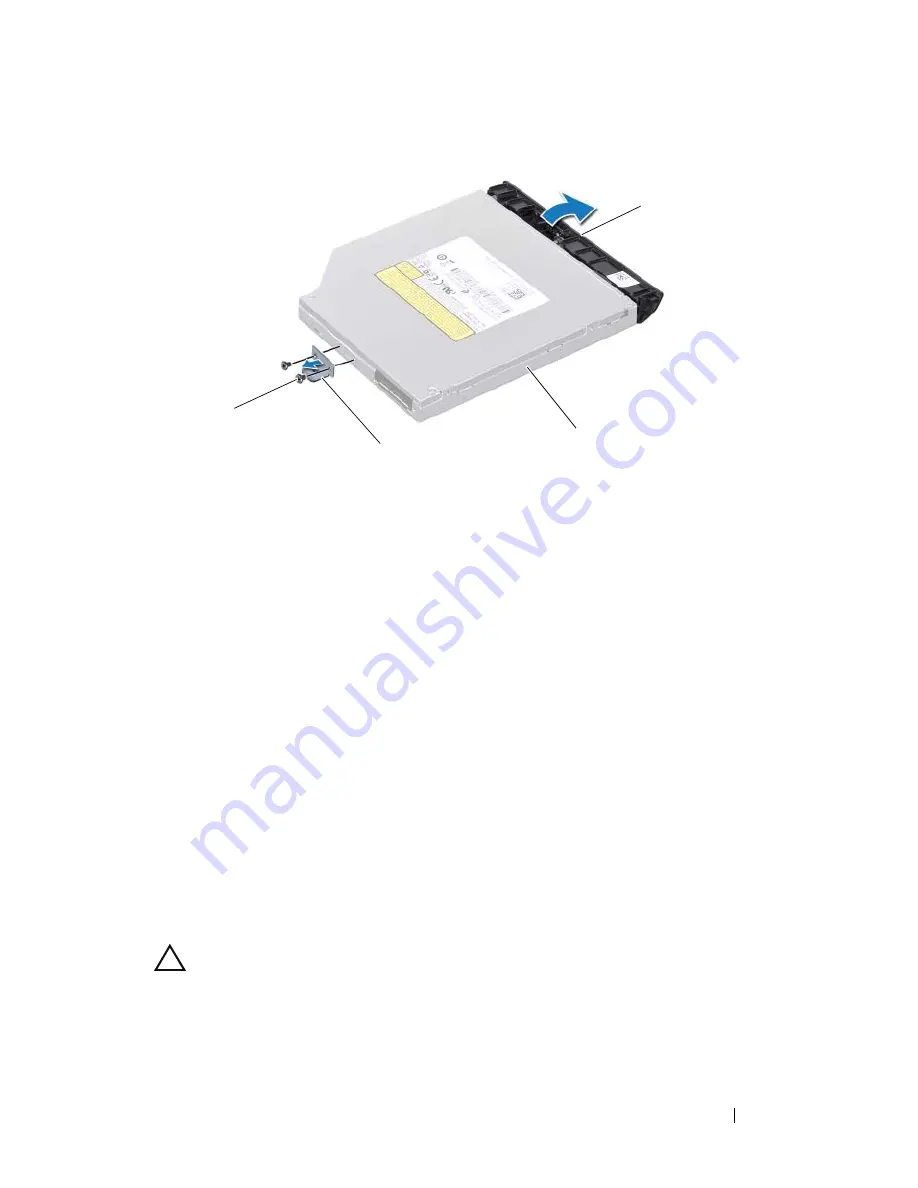
Replacing the Optical Drive
1
Follow the instructions in "Before You Begin" on page 9.
2
Align the tabs on the optical-drive bezel with the slots on the optical drive
and snap the optical-drive bezel into place.
3
Align the screw holes on the optical-drive bracket with the screw holes on
the optical drive and replace the two screws.
4
Slide the optical-drive assembly into the optical-drive compartment until
it is fully seated.
5
Replace the screw that secures the optical-drive assembly to the computer
base.
6
Replace the module cover (see "Replacing the Module Cover" on page 18).
7
Replace the battery (see "Replacing the Battery" on page 16).
CAUTION:
Before turning on the computer, replace all screws and ensure that no
stray screws remain inside the computer. Failure to do so may result in damage to
the computer.
1
screws (2)
2
optical-drive bracket
3
optical drive
4
optical-drive bezel
1
2
3
4
Summary of Contents for Inspiron 14 N4120
Page 1: ...Dell Inspiron N4110 Service Manual Regulatory model P20G Regulatory type P20G001 ...
Page 8: ...8 Contents Replacing the AC Adapter Connector 102 25 Flashing the BIOS 105 ...
Page 12: ...12 Before You Begin ...
Page 22: ...22 Optical Drive ...
Page 26: ...26 Memory ...
Page 30: ...30 Keyboard 6 Replace the battery see Replacing the Battery on page 16 ...
Page 33: ...Palm Rest Assembly 33 1 touch pad cable 2 power button cable 3 hot key board cable 2 3 1 ...
Page 36: ...36 Palm Rest Assembly ...
Page 40: ...40 Hot Key Board ...
Page 44: ...44 Power Button Board ...
Page 52: ...52 Thermal Fan ...
Page 68: ...68 Camera Module ...
Page 76: ...76 VGA Connector Board ...
Page 86: ...86 Speakers ...
Page 94: ...94 Processor Module ...
Page 103: ...AC Adapter Connector 103 ...
Page 104: ...104 AC Adapter Connector ...


