


Dell EqualLogic Configuration Guide v11.3
43
5.4
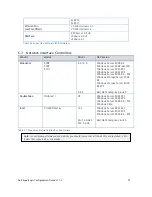
M1000e Ethernet Pass-Through I/O Module
Pass-Through modules are supported for use with EqualLogic SAN solutions. The Pass-Through module
provides a simple, direct path from each blade server’s optional Ethernet mezzanine card to an
externally accessible port. These ports can then be connected to one or more external switches that
are configured for EqualLogic SAN support as described in Section 4.3.
5.5
External Tier Stacking
The second tier for the SAN infrastructure should consist of two or more stackable switches – preferably
from the same vendor as the M1000e switches. The number of external switches required will depend
on the number of arrays being deployed as well as the type of uplink technology being used to connect
the M1000e I/O stacks to the external tier stack.
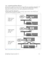
5.6
Stack to Stack Interconnect
Connecting each blade enclosure I/O module stack to the external storage tier stack using either the
1Gb/s external Ethernet ports or by using optional 10Gb/s external uplink modules.
5.6.1
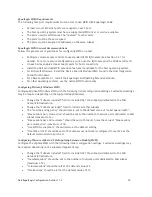
10GbE Uplink Recommendations
The following recommendations should be used when connecting
Aggregate at least two 10GbE ports from each blade I/O module stack for redundancy.
If possible, any Link Aggregation Group used for connecting the I/O modules to the external
switch stack should contain at least 2 links for redundancy. The actual number will depend on
both the number of 10GbE ports available on each stack (spread across multiple modules within
the stack) and the number of 10GbE ports available on the external switch stack.
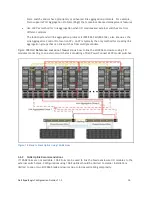
For example, each Cisco 3130X blade I/O module can have up to two 10GbE X2 ports and the
Cisco 3750-E can have at most two 10GbE X2 ports. In most configurations, your external stack
will be comprised of two switches – and a maximum of four 10GbE ports. Regardless of the
number of M1000e enclosures, there are only four available ports to use for uplinking.
Therefore, only four 10GbE ports total can be used for uplinking: two ports per redundant stack
in the dual stack blade configuration, or four ports for the single stack blade configuration.
Distribute 10GbE links among multiple switches within each I/O module stack if supported
When the blade solution consists of more than one M1000e enclosure, the 10GbE ports used for
up-linking should be distributed between multiple enclosures to protect against a complete
enclosure failure. Doing this requires that the M1000e I/O Modules be stacked.
Distribute 10GbE links evenly between all switches within the external switch stack if
supported
When the external switch stack consists of more than one switch, the 10GbE ports used for up-
linking should be distributed between all switches in the stack to protect against a switch
failure.
Use Switch vendor preferred method for link aggregation (if all switches from same vendor)
Summary of Contents for EqualLogic PS4000
Page 1: ...Dell EqualLogic Configuration Guide Dell EqualLogic Storage Infrastructure and Solutions ...
Page 11: ...Dell EqualLogic Configuration Guide v11 3 6 Figure 1 Partially Connected Controller Failover ...
Page 44: ...Dell EqualLogic Configuration Guide v11 3 39 Figure 14 Mixed Speed Redundant SAN ...


