background image


Dell EqualLogic Configuration Guide v11.3 

33 


4.4.2


Multi-Path I/O 

There are generally two types of multi-path access methods for communicating from a host to an 
external device.  For general networking communications, the preferred method of redundant 
connections is the teaming of multiple NICs into a single, virtual network connection entity.  For 
storage, the preferred method of redundant connection is the use of Multi-Path IO (MPIO).  Though 
some storage solution can and do support either method for iSCSI connectivity, EqualLogic requires the 
use of MPIO to enable multiple NIC/HBA connections to be utilized for access to an EqualLogic SAN. 


Note:

 As a best practice, we recommend using the same NIC devices in your server for all 

connection paths to the iSCSI SAN. This will minimize the complexity of server configuration 
management. 

For maximum performance, ensure that the PCI express slot hosting the network controller has 
the same specifications as the network controller. For example, if the network controller has a 
PCIe x8 interface then ensure that it is installed into a PCIe slot that can support 8 or more PCIe 
lanes. 

Figure 12 Redundant NIC Connections from Server to SAN using two installed PCI-E NICs


Summary of Contents for EqualLogic PS4000

Page 1: ...Dell EqualLogic Configuration Guide Dell EqualLogic Storage Infrastructure and Solutions ...

Page 2: ...LIED WARRANTIES OF ANY KIND 2010 Dell Inc All rights reserved Reproduction of this material in any manner whatsoever without the express written permission of Dell Inc is strictly forbidden For more information contact Dell Dell the DELL logo and the DELL badge PowerConnect Dell EqualLogic PowerEdge and PowerVault are trademarks of Dell Inc Broadcom is a registered trademark of Broadcom Corporatio...

Page 3: ...roller Failover 5 2 3 4 Firmware 7 2 4 RAID Policies 9 2 4 1 RAID 5 9 2 4 2 RAID 6 10 2 4 3 RAID 10 11 2 4 4 RAID 50 12 3 Peer Storage Operations 14 3 1 Groups 14 3 2 Pools 14 3 3 Volumes 15 3 3 1 Volume Attributes 16 3 3 2 Volume Features 17 3 3 3 Thin Provisioning 17 3 3 4 Snapshots 18 3 3 5 Cloning 18 3 3 6 Replication 19 3 3 7 Clustering 24 4 SAN Design 25 4 1 Implementation of Standards 25 4 ...

Page 4: ...gle M1000e Enclosure Integration 41 5 3 Multiple M1000e Enclosure Integration 41 5 4 M1000e Ethernet Pass Through I O Module 43 5 5 External Tier Stacking 43 5 6 Stack to Stack Interconnect 43 5 6 1 10GbE Uplink Recommendations 43 5 6 2 1GbE Uplink Recommendations 44 Appendix A Network Ports and Protocols 47 A 1 Required Ports and Protocols 47 A 2 Optional Ports and Protocols 47 Appendix B Recomme...

Page 5: ... 2 Enabling the PortFast Option to Configure STP Edge Ports 59 E 3 Configuring Flow Control 59 E 4 Disabling Unicast Storm Control 59 E 5 Configuring Jumbo Frames 60 Appendix F Cisco IOS based Switch Configuration 61 F 1 Enabling the PortFast Option to Configure STP Edge Ports 62 F 2 Configuring Flow Control 62 F 3 Disabling Unicast Storm Control 63 F 4 Configuring Jumbo Frames 63 Related Publicat...

Page 6: ...d be used strictly as a guide in planning an EqualLogic SAN solution It should not be considered a statement of support for any specific configuration Actual viability of any configuration will depend on the capabilities of the individual components switches network interface controllers initiators etc that make up the SAN infrastructure 1 1 Audience This configuration guide is intended for storag...

Page 7: ...s for Peer Storage The four digit model number indicates the major feature sets and generational information The first digit is the family and is typically referred to as the x thousand family where x is currently either 5 or 6 The second digit designates the chassis form factor 16 drives vs 48 drives The last two are digits designate the controller type 00 indicates a controller with 1GbE ports 1...

Page 8: ...0 2048 Snapshots of a volume 512 128 Replicas of a volume 512 128 Replication partners per group 16 2 Replication partners per volume 1 1 Volumes in a collection 8 8 Collections in a group snapshot and replication 100 100 Volume connections per pool and per group each time an iSCSI initiator connects to a volume counts as a connection 2048 a with 4 pools maximum 512 per pool 4096 b with 4 pools ma...

Page 9: ...ler Type Faceplate Network Interfaces Storage Type Notes Type 1 3 x 1GbaseT 3 x 1Gb SFP combo SATA Original Controller Design PS50 PS2400 1GB Cache Type 2 3 x 1GbaseT 3 x 1Gb SFP combo SATA PS50 PS2400 1GB Cache Type 3 SAS Type 3 SATA 3 x 1GbaseT SAS SATA PS3000 PS5000 1GB Cache Small Form Factor Cannot mix Type 3 SAS with Type 3 SATA Type 4 3 x 1GbaseT SAS PS3000 PS5000 1GB Cache Small Form Facto...

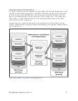
Page 10: ...thernet port on the active controller that is connected to the SAN must have its corresponding port on the passive controller also connected to the same SAN network In the event of a controller failure the passive controller will immediately activate and continue to process all data requests to the array The following changes occur during fail over The backup controller automatically enables each ...

Page 11: ...Dell EqualLogic Configuration Guide v11 3 6 Figure 1 Partially Connected Controller Failover ...

Page 12: ...ce improvements The firmware version number takes the following form X Y Z X is used to identify the major release number This changes when there are very significant changes in the features and functionality Y is the minor release number This changes as new minor features or improvements in existing features are made for a given major release Z denotes maintenance releases This changes whenever a...

Page 13: ... iSCSI initiator configuration settings that will minimize potential for I O disruption during the upgrade process Latest updates to the supported firmware upgrade paths In addition to the Release Notes the process for updating controller firmware is described in detail in the following document Support ID required for login access PS Series Storage Arrays Updating Storage Array Firmware available...

Page 14: ...arity blocks are not located on a single disk in the RAID set RAID 5 implementations can tolerate a single drive failure without data loss For EqualLogic arrays using a RAID 5 policy Table 5 shows the drive layouts that are enforced based on the number of drives in each array and the hot spare configuration Disk Drives Hot Spare No Hot Spare 7 6 Data Parity 1 Hot spare RAID Policy for RAID 5 witho...

Page 15: ... failures per RAID set at the same time without data loss RAID 6 is not recommended for workloads consisting mainly of random writes For EqualLogic arrays using a RAID 6 policy Table 7 shows the drive layouts that are enforced based on the number of drives in each array and the hot spare configuration Disk Drives Hot Spare No Hot Spare 7 6 Data Parity 1 Hot spare 7 Data Parity 8 7 Data Parity 1 Ho...

Page 16: ...mplementations can tolerate one drive failure per mirror pair For EqualLogic arrays using a RAID 10 policy Table 9 shows the drive layouts that are enforced based on the number of drives in each array and the hot spare configuration Disk Drives Hot Spare No Hot Spare 7 6 Data 3 mirrors 1 Hot spare N A a 8 6 Data 3 mirrors 2 Hot spares 8 data 4 mirrors 14 12 Data 6 mirrors 2 Hot spares 14 Data 7 mi...

Page 17: ...t are enforced based on the number of drives in each array and the hot spare configuration Disk Drives Hot Spare No Hot Spare 7 6 Data Parity 1 Hot spare N A a 8 6 Data Parity 2 Hot spares 8 Data Parity 14 12 Data Parity 2 Hot spares 14 Data Parity 16 14 Data Parity 2 Hot spares 16 Data Parity 48 b 46 Data Parity 2 Hot spares N A c a RAID 50 requires an even number of disk drives A 7 drive configu...

Page 18: ...000 2000 7 b 1000 8 c 1000 14 d 740 2500 4000 5000 16 600 1200 1752 3000 3600 4800 5400 6000 7200 9000 12000 48 19500 23400 39000 78000 a Solid State Disk b Legacy PS50E c PS4000E and PS6000E only d Legacy PS70E PS100E PS100X PS200E PS300E and PS400E Table 12 RAID 50 Total Storage Available with Hot Spares in GB ...

Page 19: ...ways at least one pool in any group and it is called the default pool unless the name is changed Regardless of the name of this pool it is always considered the default storage pool All newly added members are automatically assigned to the default pool The default pool cannot be deleted Pools can be used as part of an overall tiered storage strategy for the SAN Tiered storage is storage that is di...

Page 20: ...ning a unique RAID policy Do not mix arrays with different drive technologies SATA SAS SSD within a single pool unless they are running a unique RAID policy Do not mix arrays with different controller speeds 1GbE 10GbE within a single pool unless they are each running unique RAID policies To override the automated performance decisions for a specific volume indicate a preferred RAID type for that ...

Page 21: ...racters Volumes are assigned a unique iSCSI Qualified Name iqn that consists of the following parts iqn followed by a period Year and Month of first full month that the naming authority was registered with standards body EqualLogic s value is 2001 5 followed by a The storage provider s domain name in reverse order For example com equallogic A colon Vendor specified information to identify an iSCSI...

Page 22: ... the maximum in use space setting the volume will go into an offline state Converting a volume to a thin provisioned volume may not reduce the physical allocation of space the volume is using Actual physical space recovered will depend on previous writing patterns for the OS file system hosted on the volume All initial settings for minimum volume reserve In use volume reserve warning level and max...

Page 23: ...s value can be set to a lower value based on the application s data change rate snapshot backup plan or role that the snapshot will be used The following items should be considered when determine the size of a volume s snapshot reserve Data change rate for the application s who is using the volume Defragmentation policy of the OS or application using the volume The role or purpose for creating the...

Page 24: ...ness applications and data By replicating business critical volumes you ensure that your business operations can resume quickly on a partner group in the event of a disaster on the primary group You also have the ability to restore the configuration to its original state if the problem on the original group can be corrected The replication process does not require placing volumes offline Thus you ...

Page 25: ...ction of the path for the Fast Failback replication feature if it is enabled for the replica set Figure 5 shows how a single group can support replication of multiple primary volumes to different secondary replication partner groups Figure 6 shows how you can create bi directional replication paths between partner groups Figure 7 shows a common scenario in which multiple primary groups replicate t...

Page 26: ...Dell EqualLogic Configuration Guide v11 3 21 Figure 5 Replication Partnerships with Multiple Groups ...

Page 27: ...Dell EqualLogic Configuration Guide v11 3 22 Figure 6 Partner Groups with Bi Directional Replication Figure 7 Multiple Groups Replicating to a Single Secondary Group ...

Page 28: ...group for Replication Reserve and Local Reserve plus delegated space for storing replica sets in the secondary group This is illustrated in Figure 8 below A single delegated space on the secondary group must be used for all volumes received from a specific primary group Delegated space for a replication partnership must be assigned to a pool the Default pool by default Delegated space for differen...

Page 29: ...in the Group Manager Help documentation b Start with 105 then add to that the maximum number of replicas expected to be stored in the replica set minus 1 multiplied by the expected Change Rate Table 14 Replication Space Sizing Guidelines 3 3 7 Clustering To support a shared storage environment EqualLogic allows concurrent access to any volume Concurrent volume access is enabled on a per volume bas...

Page 30: ... iSCSI target names for group volumes Once the IP address of an iSNS server is entered in an iSCSI initiator s configuration utility the setting is persistent across initiator sessions A PS Series group can be configured to register with up to three iSNS servers 4 2 General Requirements and Recommendations For EqualLogic PS Arrays the following general SAN design requirements apply For all members...

Page 31: ...d to iSCSI traffic even on dedicated switches If necessary create a second VLAN for management traffic The actual VLAN configuration of your iSCSI SAN will be dictated by your SAN network design requirements and the features of the iSCSI SAN switches being used Jumbo frames should be enabled If you choose to use jumbo frames then all nodes in the SAN fabric must have jumbo frames enabled For best ...

Page 32: ...u should use switches that have the ability to transmit pause frames to external devices in the event that the device cannot adequately forward traffic in a timely fashion Support for Jumbo Frames This is not a requirement But the use of jumbo frames may yield desirable results Most iSCSI SAN implementations should benefit from using jumbo frames The actual impact on SAN throughput when using jumb...

Page 33: ... provide the preferred method for creating an inter switch connection within a Layer 2 network infrastructure Stacking is typically accomplished using a vendor proprietary high bandwidth low latency interconnect that allows two or more switches to be connected in such a way that each switch becomes part of a larger virtual switch A stackable switch will provide a set of dedicated stacking ports In...

Page 34: ...regation solution is designed to reduce or eliminate the need and the overhead of the Spanning Tree Protocol that must be used in the two previous options If available these proprietary options should be considered They may be very useful in allowing the network administrator to create a more efficient multi switch layer 2 network infrastructure for a SAN Be aware that these proprietary solutions ...

Page 35: ...th for each array added 10GbE switches attached to 10GbE array controllers 1 5 arrays 20 30Gb of IST bandwidth between each switch 6 arrays At least 6Gb of IST bandwidth per array between each switch 1GbE switches connecting to 10GbE switches in a mixed speed SAN Actual requirements will vary For more details see Section 4 6 Integrating 1GbE and 10GbE SANs Table 16 Switch Interconnect Design Guide...

Page 36: ...nderstand the stacking technology and limit stack size in accordance with total throughput requirements and connection counts Link Aggregation Groups LAG Create a data path between switches in one location or subnet with those in another location or subnet Pros Leverages Ethernet standard extensions Can be used to interconnect switches from different vendors Can use Link Aggregation Protocols LACP...

Page 37: ... Installed NIC 2 NIC Connections to SAN X X X X X X Table 18 Redundant Server NIC Configurations Using the Dell PowerEdge R610 server as an example you configure redundant connection paths to the SAN switches as shown in Figure 11 below The R610 server shown in Figure 11 has one additional dual port PCI E NIC installed This configuration leaves two unused ports on the LOM controller for connecting...

Page 38: ... connectivity EqualLogic requires the use of MPIO to enable multiple NIC HBA connections to be utilized for access to an EqualLogic SAN Note As a best practice we recommend using the same NIC devices in your server for all connection paths to the iSCSI SAN This will minimize the complexity of server configuration management For maximum performance ensure that the PCI express slot hosting the netwo...

Page 39: ...IO Configure Microsoft Windows MPIO with the following initial configuration settings Customized settings may be required depending on the supported application s Change the Subnets included field to include ONLY the subnet s dedicated to the SAN network infrastructure Change the Subnets excluded field to include all other subnets The Load balancing policy should remain set to the default value of...

Page 40: ...ices recommendations will be used to derive all examples Unless otherwise stated all reference designs will promote end to end host to volume redundant paths A minimal number of switches will be illustrated that allows the design concept to be understood Actual implementations will vary depending on customer s actual network infrastructure If sharing physical switches with other non SAN traffic as...

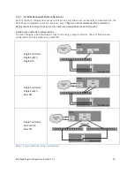
Page 41: ... recommended for production deployment since they do not provide end to end redundant connection paths Single Array Controller Configurations You can configure a Dell EqualLogic array to run using a single controller Table 19 below shows configurations using a single array controller Single Controller Single Switch Single NIC Single Controller Single Switch Dual NIC Single Controller Dual Switch D...

Page 42: ...nfigure a Dell EqualLogic array to run using dual controllers Table 20 below shows configurations using a single array controller Dual Controller Single Switch Single NIC Dual Controller Dual Switch Single NIC Dual Controller Single Switch Dual NIC Table 20 Dual Controller Array Configurations ...

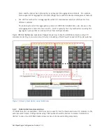
Page 43: ... design of a mixed speed iSCSI SAN is the feature set and port densities provided by the Ethernet switches you will be using in your SAN To create a redundant mixed speed iSCSI SAN at a minimum we recommend that you start with dual 1GbE and dual 10GbE switches Figure 14 shows an example SAN design where two switches of each type are used The design in Figure 14 is based on the features provided by...

Page 44: ...Dell EqualLogic Configuration Guide v11 3 39 Figure 14 Mixed Speed Redundant SAN ...

Page 45: ...with external switch stacks via aggregated links as described in Section 4 3 1 Use the switch vendor preferred method for link aggregation if all switches from same vendor Use LACP for link aggregation when I O modules and external switches are from different vendors Using 10GbE port options where available See Figure 18 If blade I O modules are stacked o Aggregate at least two 10GbE ports from ea...

Page 46: ...e two redundant switches in the fabric slots B1 B2 or C1 C2 should be stacked together as shown in Figure 15 below Figure 15 Single Enclosure Switch Stacking 5 3 Multiple M1000e Enclosure Integration Two options are available when configuring the blade I O modules into stacks Dual I O Module Stacks The I O modules in one half of the redundant fabric B1 or C1 of each M1000e enclosure should be stac...

Page 47: ...uration scales the number of M1000e blade enclosures to of the number allowed in the Dual Stack configuration For Cisco Catalyst 3130 family of I O modules the enclosure limit would be 4 M1000e s and for the PowerConnect M6220 I O modules the enclosure limit would be 5 M1000e s This configuration is not a preferred method for stacking M1000e blade enclosures See the Dual I O Module Stack in the pr...

Page 48: ...tack should contain at least 2 links for redundancy The actual number will depend on both the number of 10GbE ports available on each stack spread across multiple modules within the stack and the number of 10GbE ports available on the external switch stack For example each Cisco 3130X blade I O module can have up to two 10GbE X2 ports and the Cisco 3750 E can have at most two 10GbE X2 ports In mos...

Page 49: ...typically the only method for creating link aggregation groups that can link switches from multiple vendors Figure 18Error Reference source not found shows how to link the M1000e enclosures using I O modules connecting to an external switch stack consisting of Dell PowerConnect 62XX model switches Figure 18 Stack to Stack Uplink Using 10GbE Links 5 6 2 1GbE Uplink Recommendations If 10GbE links ar...

Page 50: ...stack if supported When the external switch stack consists of more than one switch the 1GbE ports used for up linking should be distributed between all switches in the external switch stack to protect against a switch failure Use Switch vendor preferred method for link aggregation if all switches from same vendor Some switch vendors have proprietary or enhanced link aggregation protocols For examp...

Page 51: ...Dell EqualLogic Configuration Guide v11 3 46 Figure 19 Stack to Stack Uplink Using 1 GbE Links ...

Page 52: ...To the group IP address and all individual member IP addresses EqualLogic Internal UDP 161 SNMP Management operations TCP 9876 Internal iSCSI intra system control TCP 25555 Internal Group communication TCP 20002 Internal Event logging Table 21 Required Ports and Protocols A 2 Optional Ports and Protocols Table 22 lists the optional ports and protocols used for management and alerts They are not re...

Page 53: ...Diagnostics TCP 20 FTP Software update and diagnostic procedures to all individual member IP addresses TCP 25 SMTP E mail and diagnostic notifications from all individual member IP addresses to the configured SMTP server Table 22 Optional Ports and Protocols ...

Page 54: ...rastructure component to be used within a Dell EqualLogic SAN solution as long as it meets minimum standards defined in Section 4 3 required for use within a Dell EqualLogic SAN infrastructure Dell makes no guarantee that these switches will meet the customer s expectations for performance or scalability Dell Labs has developed a set of tests to help determine if an infrastructure component will o...

Page 55: ...ckard ProCurve 3500yl 48G K 12 12 Juniper EX4200 48 10 2R1 8 Nortel Networks ERS 5510 48T 5 0 0 2 Table 23 Recommended Switches 1GbE B 2 Recommended 10GbE Switches Vendor Model Firmware Brocade 8000 8000e 6 3 0a Cisco Nexus 50x0 NX OS v4 2 1 N1 1 Dell PowerConnect 8024F 3 1 1 9 PowerConnect 8024 3 1 1 9 PowerConnect M8024 3 1 2 5 Powerconnect B 8000 B 8000e 6 3 0a Table 24 Recommeded Switches 10Gb...

Page 56: ...ad Product Operating Systems Supported Broadcom iSCSI offload NetExtreme 5708 5709 57711 Microsoft Windows 2008R2 Microsoft Windows 2008 Microsoft Windows 2003 Microsoft Windows Storage Server 2003 R2 VMware vSphere 4 1 Emulex iSCSI Offload Oce101012 I Microsoft Windows 2008R2 Qlogic branded only HBA QLA4050 QLA4052 Microsoft Windows 2008R2 Microsoft Windows 2008 Microsoft Windows 2003 Microsoft W...

Page 57: ...or 3 22 Cisco Cisco Open Source iSCSI Initiator Citrix XenServer 4 0 XenServer 4 1 XenServer 5 0 XenServer 5 5 HP HP UX 11i V1 PA RISC HP UX 11i V2 PA RISC Intel Sept 2004 update only IBM AIX 5 2 ML03 or later Microsoft Windows Server 2008 R2 Windows Server 2008 All SPs Windows Server 2003 SP1 Windows Server 2003 SP2 Windows Server 2003 R2 SP2 Windows Storage Server 2003 R2 Windows Storage Server ...

Page 58: ...003 SP1 Windows Server 2003 SP2 Windows Server 2003 R2 SP2 Windows Storage Server 2003 R2 Windows Storage Server 2003 R2 SP2 Red Hat Enterprise Linux 5 DoubleTake WinBoot i V2 Windows Server 2003 SP1 Windows Server 2003 SP2 Windows Server 2003 R2 SP2 Windows Vista Intel Pro1000 Family 12 3 Drv 12 0 A00 FW 2 4 06 Windows Server 2003 SP1 Windows Server 2003 SP2 Windows Server 2003 R2 SP2 Red Hat Ent...

Page 59: ...rConnect 54xx switch must use the interface command and the port references are in the form of g port For example Port 10 on the Powerconnect 5424 would be referenced as console config interface ethernet g10 To reference a range of ports the interface range command must be used with the port reference in the form of g begport endport For example to reference all ports between port g1 and port g15 ...

Page 60: ...ree mode rstp console config interface ethernet g10 console config if spanning tree portfast console config if exit console config exit console copy running config startup config console exit D 3 Configuring Flow Control Flow control on the PowerConnect 54xx Family of switches is off by default To enable flow control on all ports in the switch use the system flow control command Flow control only ...

Page 61: ... a single port of a PowerConnect 5448 switch console configure console config interface Ethernet g1 console config if no port storm control broadcast enable console config if exit console config exit console copy running config startup config console exit The following steps are an example of how to disable storm control on all ports of a PowerConnect 5448 switch console configure console config i...

Page 62: ... default To enable jumbo frames on the PowerConnect 54xx switch use the port jumbo frame global configuration command Jumbo frames are enabled on all ports on a switch when enabled console configure console config port jumbo frame console config exit console copy running config startup config console exit ...

Page 63: ...if the web interface is preferred E 1 Interface Naming Convention The conventions for naming interfaces on Dell PowerConnect 62xx family of switches are as follows Unit Interface ID each interface is identified by the Unit followed by a symbol and then the Interface ID see below For example 2 g10 identifies gigabit port 10 within the second unit of a stack Unit the unit number is used only in a st...

Page 64: ...figuring Flow Control Flow control on the PowerConnect 62xx Family of switches is off by default To enable flow control on all ports in the switch use the flowcontrol command To enable flow control on all ports of a PowerConnect 6248 enter the following commands console configure console config flowcontrol console config exit console copy running config startup config console exit E 4 Disabling Un...

Page 65: ...e copy running config startup config console exit E 5 Configuring Jumbo Frames Jumbo frames are not enabled by default To enable jumbo frames on the Powerconnect 62xx switch use the mtu interface configuration command with a parameter of 9216 Because the mtu command is an interface configuration command each port must be individually configured with the mtu command All ports on a switch can be con...

Page 66: ...eive a new stack member number and it keeps that number until another is assigned to it Non Stackable switches have a stack member number of 1 The switch port LEDs can be configured in Stack mode to identify the stack member number of a switch Module number The module or slot number on the switch is always 0 Port number Reflects the actual port number on the switch Port numbers always begin at 1 s...

Page 67: ...Use the spanning tree portfast default global configuration command to globally enable the PortFast feature on all non trunking ports This example shows how to globally enable PortFast by default on all access ports Switch config terminal Switch config spanning tree portfast default Switch config end Switch copy running config startup config For additional information on understanding and configur...

Page 68: ...ction describes how to disable unicast storm control on Cisco Catalyst 3750 and 2970 switches The following example shows how to disable unicast storm control on Gigabit Ethernet interface 0 15 on switch 1 and verify the configuration Switch enable Switch configure terminal Switch config interface gigabitethernet1 0 15 Switch config if no storm control unicast level Switch config if exit Switch co...

Page 69: ...hows the output when you try to set Gigabit Ethernet interfaces to an out of range value Switch config system mtu jumbo 25000 Invalid input detected at marker Once the switch completes reload the configuration can be verified by entering the following commands Switch enable Switch configure t Switch config show system mtu Switch config exit The commands shown next are used to enable an individual ...

Page 70: ...figuration Guide v11 3 65 For more information on configuring Jumbo Frames or Giant Frames on Catalyst switches see http www cisco com en US products hw switches ps700 products_configuration_example09186a00 8010edab shtml ...

Page 71: ...egistration required Integrating EqualLogic PS6x10 Arrays with Existing SANs Understanding Data Replication Between Dell EqualLogic PS Series Groups Published in 2009 10 GbE Servers Storage and Virtualization Interoperability Review and Highlights Benefits and Best Practices for Deploying SSDs in an OLTP Environment Using Dell EqualLogic PS Series EqualLogic support site registration required Conf...

Page 72: ...ualLogic SANs MSTP Interoperability of Dell PowerConnect 62XX Switches Using Active Directory for Account Authentication to a PS Series Group VLAN Interoperability of the Dell PowerConnect M6220 Published in 2006 Aligning Disk Sectors for Optimal Performance in Microsoft Windows Published in 2005 PS Series Groups Network Connection and Performance Guidelines Red Hat Linux Clusters Using a PS Serie...

Page 73: ...THIS WHITE PAPER IS FOR INFORMATIONAL PURPOSES ONLY AND MAY CONTAIN TYPOGRAPHICAL ERRORS AND TECHNICAL INACCURACIES THE CONTENT IS PROVIDED AS IS WITHOUT EXPRESS OR IMPLIED WARRANTIES OF ANY KIND ...

Reviews: