Dell EMC PowerEdge XE7440 Installation And Service Manual Download Page 56

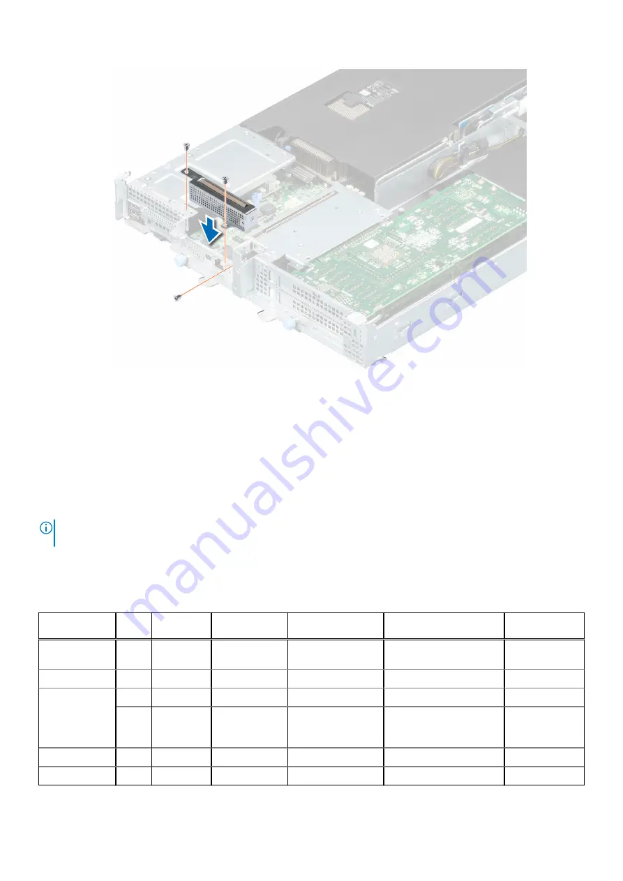
Figure 22. Installing the PCIe dummy bracket

Next steps

1.

Install the sled

.

2. Follow the procedure listed in 

After working inside your system

.

Expansion cards

NOTE:

 A missing or an unsupported expansion card riser logs a System Event Log (SEL) event. This does not prevent your

system from powering on and no BIOS, POST messages, or F1 or F2 pause is displayed.

PCIe slot priority

Table 7. Supported expansion options 

Location

Width Card

length

Bracket

height

Controlling CPU

PCIe width

Usage

DCS_MEZZ
slot-1

NA

NA

NA

CPU1

X8

miniPERC

OCP Slot-3

NA

NA

NA

CPU1

X8

OCP 2.0

PCIe riser
Slot-4

DW

FL

FH

CPU1

X16

FE1/NV100S

SW

FL

FH

CPU1

X16

CX4 NIC /
BCM57414 NIC/
T4

PCIe Slot-5

NA

NA

NA

CPU2

X8

PERC

PCIe Slot-6

NA

NA

NA

CPU2

X8

PERC

56

Installing and removing system components

Summary of Contents for EMC PowerEdge XE7440

Page 1: ...Dell EMC PowerEdge XE7440 Installation and Service Manual Regulatory Model B24S Series Regulatory Type B24S001 August 2020 Rev A00 ...

Page 2: ...ential damage to hardware or loss of data and tells you how to avoid the problem WARNING A WARNING indicates a potential for property damage personal injury or death 2020 Dell Inc or its subsidiaries All rights reserved Dell EMC and other trademarks are trademarks of Dell Inc or its subsidiaries Other trademarks may be trademarks of their respective owners ...

Page 3: ...ll OS drivers 19 Downloading drivers and firmware 20 Channel Firmware Commodities 20 Chapter 4 Pre operating system management applications 24 Options to manage the pre operating system applications 24 System Setup 24 Viewing System Setup 24 System Setup details 25 System BIOS 25 iDRAC Settings utility 43 Device Settings 43 Dell Lifecycle Controller 43 Embedded system management 43 Boot Manager 43...

Page 4: ... riser board 67 Installing the mini PERC riser board 68 Mini PERC adaptor board 69 Removing the mini PERC adaptor board 69 Installing the mini PERC adaptor board 70 Network daughter card 71 Removing the OCP card 71 Installing the OCP card 72 Motherboard bridge module 73 Removing the motherboard bridge module 73 Installing the motherboard bridge module 74 Motherboard interposer board 75 Removing th...

Page 5: ...ing the system board 116 Installing the system board 118 Restoring Service Tag using Easy Restore 119 Trusted Platform Module 120 Upgrading the Trusted Platform Module 120 Initializing TPM for users 121 Initializing the TPM 1 2 for users 121 Initializing the TPM 2 0 for users 121 Chapter 6 Jumpers and connectors 122 System board connectors 122 System board jumper settings 123 Disabling forgotten p...

Page 6: ...ndicator codes 132 Using system diagnostics 132 Dell Embedded System Diagnostics 133 Chapter 9 Getting help 134 Contacting Dell EMC 134 Documentation feedback 134 Accessing system information by using QRL 134 Quick Resource Locator for XE7100 XE7420 and XE7440 systems 135 Receiving automated support with SupportAssist 135 Recycling or End of Life service information 135 Chapter 10 Documentation re...

Page 7: ...ument provides an overview about the system information about installing and replacing components technical specifications diagnostic tools and guidelines to be followed while installing certain components 1 About this document 7 ...

Page 8: ... for intelligent video analytics and media streaming Topics Rear view of the PowerEdge XE7440 sled Inside the system Locating the Express Service Code and Service Tag System information labels Rail sizing and rack compatibility matrix Rear view of the PowerEdge XE7440 sled Figure 1 Rear view of XE7440 sled Table 1 Back panel features Item Indicator button or connector Icon Description 1 USB 3 0 po...

Page 9: ...DRAC or NIC port Enables you to remotely access iDRAC For more information see the Integrated Dell Remote Access Controller User s Guide at https www dell com idracmanuals 8 Rear power button N A Enables you to power on the sled while accessing it from the rear 9 DW PCIe card N A Enables you to connect FE1 card or GPGPU card or NIC card For more information see the Expansion cards section 10 Low P...

Page 10: ...Tag The unique Express Service Code and Service Tag are used to identify the system The information tag is located on the front of the system that includes system information such as Service Tag Express Service Code Manufacture date NIC MAC address QRL label and so on If you have opted for the secure default access to iDRAC the Information tag also contains the iDRAC secure default password If you...

Page 11: ...formation label The Mini Enterprise Service Tag MEST label is located on the rear of the system that includes Service Tag ST Express Service Code Exp Svc Code and Manufacture Date Mfg Date The Exp Svc Code is used by Dell EMC to route support calls to the appropriate personnel Alternatively the Service Tag information is located on a label on left wall of the chassis PowerEdge XE7440 overview 11 ...

Page 12: ...System information labels Figure 4 System board connectors 12 PowerEdge XE7440 overview ...

Page 13: ...Figure 5 Express Service Tag PowerEdge XE7440 overview 13 ...

Page 14: ...Figure 6 Memory information 14 PowerEdge XE7440 overview ...

Page 15: ...Figure 7 System tasks PowerEdge XE7440 overview 15 ...

Page 16: ...vailable at https i dell com sites csdocuments Business_solutions_engineering Docs_Documents en rail rack matrix pdf The document provides the information that is listed below Specific details about rail types and their functionalities Rail adjustability ranges for various rack mounting flange types Rail depth with and without cable management accessories Rack types that are supported for various ...

Page 17: ...ctive as a system administrator and improve the overall availability of Dell EMC servers iDRAC alerts you to system issues helps you to perform remote management and reduces the need for physical access to the system Options to set up iDRAC IP address To enable communication between your system and iDRAC you must first configure the network settings based on your network infrastructure The network...

Page 18: ...ess iDRAC through the shared LOM mode if you have opted for a system that has the shared LOM mode enabled Options to log in to iDRAC To log in into the iDRAC Web User Interface open a browser and enter the IP address You can log in to iDRAC as iDRAC user Microsoft Active Directory user Lightweight Directory Access Protocol LDAP user In the login screen displayed if you have opted for secure defaul...

Page 19: ...rs and firmware section You can also choose any one of the following options to download the firmware For information about how to download the firmware see the documentation links provided in the table Table 4 Options to download firmware Option Documentation link Using Dell Remote Access Controller Lifecycle Controller iDRAC with LC www dell com idracmanuals Using Dell Repository Manager DRM www...

Page 20: ...requirements the following commodities were enabled in the XE7100 or XE7420 or XE7440 NVMe Micron 7300PRO 960 G with 2 5 7 MM carrier for caching journaling logging NVMe Micron 7300PRO 1920 G with 2 5 7 MM carrier for caching journaling logging M 2 NVMe Micron 960 G PCIE Storage Option with 12 16 or 20 slots per card for flash memory M 2 NVMe Micron 1 92 TB PCIE Storage Option with 12 16 or 20 slo...

Page 21: ...rted Secure Enterprise Key Manager SED support Not supported Not supported CloudLink Not supported Not supported SupportAssist for Enterprise Not supported Not supported ServiceNow Not supported Not supported Ansible Enablement Not supported Not supported Quicksync2 Not supported Not supported Third party Connectors Nagios Tivoli CA etc Not supported Not supported Vendor tools The vendor tools req...

Page 22: ...00PRO in iDRAC inventory M 2 NVMe Micron 960 G 1 92 TB PCIE Storage Option with 12 16 or 20 slots per card See the screenshot below as to how this drive is reported in iDRAC Inventory 22 Initial system setup and configuration ...

Page 23: ...ron PCIe storage in iDRAC inventory Adapter for NVMe M 2 PCIe storage option Single and Dual in iDRAC Inventory Figure 12 Adapter for NVMe M 2 PCIe storage options in iDRAC inventory Initial system setup and configuration 23 ...

Page 24: ...igure the BIOS settings iDRAC settings and device settings of your system NOTE Help text for the selected field is displayed in the graphical browser by default To view the help text in the text browser press F1 You can access system setup by one of the following Standard graphical browser The browser is enabled by default Text browser The browser is enabled by using Console Redirection Viewing Sy...

Page 25: ...he operating system begins to load before you press F2 wait for the system to finish booting and then restart the system and try again 3 On the System Setup Main Menu screen click System BIOS System BIOS Settings details About this task The System BIOS Settings screen details are explained as follows Option Description System Information Provides information about the system such as the system mod...

Page 26: ...s options to change the system date and time System Information You can use the System Information screen to view system properties such as Service Tag system model name and BIOS version Viewing System Information To view the System Information screen perform the following steps Steps 1 Power on or restart your system 2 Press F2 immediately after you see the following message F2 System Setup NOTE ...

Page 27: ...gs screen perform the following steps Steps 1 Power on or restart your system 2 Press F2 immediately after you see the following message F2 System Setup NOTE If the operating system begins to load before you press F2 wait for the system to finish booting and then restart the system and try again 3 On the System Setup Main Menu screen click System BIOS 4 On the System BIOS screen click Memory Setti...

Page 28: ...Opportunistic Self Refresh Enables or disables opportunistic self refresh feature This option is set to Disabled by default and is not supported when DCPMMs are in the system Processor Settings You can use the Processor Settings screen to view the processor settings and perform specific functions such as enabling virtualization technology hardware prefetcher logical processor idling Viewing Proces...

Page 29: ...LLC or disable the option to not enter the dead lines in LLC Directory AtoS Enables or disables the Directory AtoS AtoS optimization reduces remote read latencies for repeat read accesses without intervening writes This option is set to Disabled by default Logical Processor Idling Enables you to improve the energy efficiency of a system It uses the operating system core parking algorithm and parks...

Page 30: ...ails are explained as follows Option Description Embedded SATA Enables the embedded SATA option to be set to AHCI Mode or RAID Mode This option is set to AHCI Mode by default Security Freeze Lock Enables you to send Security Freeze Lock command to the embedded SATA drives during POST This option is applicable only for AHCI mode This option is set to Enabled by default Write Cache Enables or disabl...

Page 31: ...s Option Description NVMe Mode Enables you to set the NVMe mode This option is set to Non RAID by default Boot Settings You can use the Boot Settings screen to set the boot mode to either BIOS or UEFI It also enables you to specify the boot order UEFI The Unified Extensible Firmware Interface UEFI is a new interface between operating systems and platform firmware The interface consists of data tab...

Page 32: ...ailure The devices are selected in the Hard Disk Drive Sequence on the Boot Option Setting menu When this option is set to Disabled only the first drive in the list is attempted to boot When this option is set to Enabled all drives are attempted to boot in the order selected in the Hard Disk Drive Sequence This option is not enabled for UEFI Boot Mode This option is set to Disabled by default Gene...

Page 33: ...ode Steps 1 On the System Setup Main Menu screen click System BIOS Boot Settings UEFI BIOS Boot Settings UEFI BIOS Boot Sequence 2 Click Boot Option Settings BIOS UEFI Boot Settings Boot Sequence NOTE Use the arrow keys to select a boot device and use the plus and minus sign keys to move the device down or up in the order 3 Click Exit and then click Yes to save the settings on exit Network Setting...

Page 34: ...or this boot One way means the HTTP server will be authenticated by the client while the client will not be authenticated by the server This option is set to None by default Integrated Devices You can use the Integrated Devices screen to view and configure the settings of all integrated devices including the video controller integrated RAID controller and the USB ports Viewing Integrated Devices T...

Page 35: ...ly field If the Embedded Video Controller is the only display capability in the system that is no add in graphics card is installed then the Embedded Video Controller is automatically used as the primary display even if the Embedded Video Controller setting is set to SR IOV Global Enable Enables or disables the BIOS configuration of Single Root I O Virtualization SR IOV devices This option is set ...

Page 36: ...tion is set to VT100 VT220 by default Redirection After Boot Enables or disables the BIOS console redirection when the operating system is loaded This option is set to Enabled by default System Profile Settings You can use the System Profile Settings screen to enable specific system performance settings such as power management Viewing System Profile Settings To view the System Profile Settings sc...

Page 37: ...is option is set to Balanced Performance by default Number of Turbo Boost Enabled Cores for Processor 1 NOTE If there are two processors installed in the system you will see an entry for Number of Turbo Boost Enabled Cores for Processor 2 Controls the number of turbo boost enabled cores for Processor 1 The maximum number of cores is enabled by default Monitor Mwait Enables the Monitor Mwait instru...

Page 38: ...stem password This option is set to Unlocked by default TPM Security NOTE The TPM menu is available only when the TPM module is installed Enables you to control the reporting mode of the TPM The TPM Security option is set to Off by default You can only modify the TPM Status TPM Activation and the Intel TXT fields if the TPM Status field is set to either On with Pre boot Measurements or On without ...

Page 39: ... Mode PK must be installed and the BIOS performs signature verification on programmatic attempts to update policy objects Deployed Mode restricts the programmatic mode transitions Secure Boot Policy Summary Specifies the list of certificates and hashes that secure boot uses to authenticate images Secure Boot Custom Policy Settings Configures the Secure Boot Custom Policy To enable this option set ...

Page 40: ...rd Prerequisites NOTE You cannot delete or change an existing system or setup password if the Password Status is set to Locked Steps 1 To enter System Setup press F2 immediately after turning on or restarting your system 2 On the System Setup Main Menu screen click System BIOS System Security 3 On the System Security screen ensure that Password Status is set to Unlocked 4 In the System Password fi...

Page 41: ...en you can set the redundant OS information This enables you to set up a physical recovery disk on the system Viewing Redundant OS Control To view the Redundant OS Control screen perform the following steps Steps 1 Power on or restart your system 2 Press F2 immediately after you see the following message F2 System Setup NOTE If your operating system begins to load before you press F2 wait for the ...

Page 42: ...ore you press F2 wait for the system to finish booting and then restart your system and try again 3 On the System Setup Main Menu screen click System BIOS 4 On the System BIOS screen click Miscellaneous Settings Miscellaneous Settings details About this task The Miscellaneous Settings screen details are explained as follows Option Description System Time Enables you to set the time on the system S...

Page 43: ...s including system deployment configuration update maintenance and diagnosis LC is delivered as part of the iDRAC out of band solution and Dell system embedded Unified Extensible Firmware Interface UEFI applications Embedded system management The Dell Lifecycle Controller provides advanced embedded system management throughout the lifecycle of the system The Dell Lifecycle Controller can be starte...

Page 44: ...aunch Lifecycle Controller Exits the Boot Manager and invokes the Dell Lifecycle Controller program System Utilities Enables you to launch System Utilities menu such as System Diagnostics and UEFI shell One shot UEFI boot menu One shot UEFI boot menu enables you to select a boot device to boot from System Utilities System Utilities contains the following utilities that can be launched Launch Diagn...

Page 45: ...s to assist you WARNING Opening or removing the system cover while the system is turned on may expose you to a risk of electric shock CAUTION Do not operate the system without the cover for a duration exceeding five minutes Operating the system without the system cover can result in component damage CAUTION Many repairs may only be done by a certified service technician You should only perform tro...

Page 46: ...elines listed in Safety instruction Steps 1 Power off the system and all attached peripherals 2 Disconnect the system from the electrical outlet and disconnect the peripherals 3 If applicable remove the system from the rack For more information see the Rail Installation Guide relevant to your rail solutions at www dell com xemanuals After working inside your system Prerequisites Follow the safety ...

Page 47: ...sled 3 Using sled handle slide the sled out of the enclosure Figure 13 Removing the sled Next steps 1 Install the sled Installing the sled Prerequisites Follow the safety guidelines listed in Safety instructions Steps 1 Hold the sled on both sides and slide the sled into the enclosure until the sled is locked to the enclosure 2 Push the sled lever under the sled and tighten the captive screws Inst...

Page 48: ...Figure 14 Installing the sled Next steps 1 Follow the procedure listed in After working inside the system 48 Installing and removing system components ...

Page 49: ...ted in the Before working inside your system 3 Remove the sled Steps 1 Hold the air shroud touch points at both ends and lift the air shroud out of the system 2 Push the retention clip down and lift the mini PERC card battery out of the air shroud NOTE Observe the cable routing of the mini PERC card battery that is below the air duct and goes between heat sink and memory sockets Figure 15 Removing...

Page 50: ... the sled Steps Hold the edges of the air shroud and lift the air shroud out of the system Figure 16 Removing the air shroud FH sled Next steps Install the shroud FH sled Installing the air shroud Prerequisites 1 Follow the safety guidelines listed in the Safety instructions 2 Follow the procedure listed in the Before working inside your system Steps 1 Push down the retention clip and press the mi...

Page 51: ... inside your system Installing the air shroud FH sled Prerequisites Follow the safety guidelines listed in the Safety instructions Steps 1 Align the slot on the air shroud with the standoff on the system 2 Lower the air shroud into the system until it is firmly seated Installing and removing system components 51 ...

Page 52: ...fety guidelines listed in the Safety instructions 2 Follow the procedure listed in the Before working inside your system 3 Remove the sled 4 Remove the air shroud 5 If required Remove the air shroud FH sled Steps 1 Disconnect the cooling fan cable that is connected to the motherboard bridge connector 2 Lift the cooling fan out of the cooling fan cage assembly 52 Installing and removing system comp...

Page 53: ...lling a cooling fan Prerequisites Follow the safety guidelines listed in the Safety instructions Steps 1 Insert a cooling fan into the cooling fan cage assembly 2 Connect the cooling fan cable to the motherboard bridge connector Installing and removing system components 53 ...

Page 54: ... bracket Removing the PCIe dummy bracket Prerequisites 1 Follow the safety guidelines listed in the Safety instructions 2 Follow the procedure listed in the Before working inside your system 3 Remove the sled Steps 1 Using the Phillips 1 screwdriver remove the three screws that secure the PCIe dummy bracket to the sled 2 Pull out the PCIe dummy bracket form the sled 54 Installing and removing syst...

Page 55: ...ng the PCIe dummy bracket Prerequisites Follow the safety guidelines listed in the Safety instructions Steps 1 Insert the PCIe dummy bracket into the sled 2 Using the Phillips 1 screwdriver secure the PCIe dummy bracket to the sled with three screws Installing and removing system components 55 ...

Page 56: ...om powering on and no BIOS POST messages or F1 or F2 pause is displayed PCIe slot priority Table 7 Supported expansion options Location Width Card length Bracket height Controlling CPU PCIe width Usage DCS_MEZZ slot 1 NA NA NA CPU1 X8 miniPERC OCP Slot 3 NA NA NA CPU1 X8 OCP 2 0 PCIe riser Slot 4 DW FL FH CPU1 X16 FE1 NV100S SW FL FH CPU1 X16 CX4 NIC BCM57414 NIC T4 PCIe Slot 5 NA NA NA CPU2 X8 PE...

Page 57: ...riser board Removing the cable M 2 riser board Prerequisites 1 Follow the safety guidelines listed in the Safety instructions 2 Follow the procedure listed in the Before working inside your system 3 Remove the sled 4 Remove the air shroud Steps 1 Using the Phillips 1 screwdriver remove the screw that secures the M 2 riser board into system board 2 Pull out the M 2 riser board 3 Disconnect the slim...

Page 58: ...Figure 23 Removing the M 2 riser board 4 Remove the screw and separate the M 2 riser board from the bracket 58 Installing and removing system components ...

Page 59: ... riser board Installing the cable M 2 riser board Prerequisites Follow the safety guidelines listed in the Safety instructions Steps 1 Place the bracket on the cable M 2 riser board and secure it by tightening the screw Installing and removing system components 59 ...

Page 60: ...e from being pinched or crimped 3 Insert and push the M 2 riser board into the system board 4 Using the Phillips 1 screwdriver secure the M2 riser board into the system board with the screw NOTE The numbers on the image do not depict the exact steps The numbers are for representation of sequence 60 Installing and removing system components ...

Page 61: ...uisites 1 Follow the safety guidelines listed in the Safety instructions 2 Follow the procedure listed in the Before working inside your system 3 Remove the sled 4 Remove the air shroud 5 Remove the PCIe dummy bracket Steps 1 Loosen the captive screw and remove the three screws securing the mini PERC card module to sled 2 Lift the mini PERC card module from the sled Installing and removing system ...

Page 62: ...ni PERC card module 3 Loosen the two captive screws and remove the mini PERC card cable 4 Disconnect the mini PERC battery cable 5 Pull the mini PERC card out of the hook from the mini PERC bracket NOTE Route the cable properly to prevent the cable from being pinched or crimped NOTE The numbers on the image do not depict the exact steps The numbers are for representation of sequence 62 Installing ...

Page 63: ...on accompanying the card Steps 1 Align and insert the mini PERC card into the hook of mini PERC bracket 2 Install the mini PERC cable into the mini PERC card and tighten two captive screws to secure the mini PERC cable 3 Connect the mini PERC battery cable to mini PERC card NOTE Route the cable properly to prevent the cable from being pinched or crimped NOTE The numbers on the image do not depict ...

Page 64: ...d 4 Align the mini PERC card module to the PCIe slot on the system board and press until the PERC riser clicks into place 5 Secure the mini PERC card module by three screws and one captive screw 64 Installing and removing system components ...

Page 65: ...rd battery Removing the mini PERC card battery Prerequisites 1 Follow the safety guidelines listed in the Safety instruction 2 Follow the procedure listed in the Before working inside your system 3 Remove the sled 4 Remove the air shroud 5 Remove the PCIe dummy bracket 6 Remove the mini PERC module Steps Disconnect the mini PERC card battery cable from mini PERC card Installing and removing system...

Page 66: ...eps Install the mini PERC card battery Installing the mini PERC card battery Prerequisites Follow the safety guidelines listed in the Safety instructions Steps Connect the mini PERC battery cable into mini PERC card 66 Installing and removing system components ...

Page 67: ...listed in After working inside the system Mini PERC riser board Removing the mini PERC riser board Prerequisites 1 Follow the safety guidelines listed in the Safety instruction 2 Follow the procedure listed in the Before working inside your system 3 Remove the sled 4 Remove the air shroud 5 Remove the PCIe dummy bracket 6 Remove the mini PERC module Installing and removing system components 67 ...

Page 68: ...he mini PERC riser board Next steps Install the mini PERC riser board Installing the mini PERC riser board Prerequisites Follow the safety guidelines listed in the Safety instruction Steps Insert the mini PERC riser board on system board slot 68 Installing and removing system components ...

Page 69: ... Mini PERC adaptor board Removing the mini PERC adaptor board Prerequisites 1 Follow the safety guidelines listed in the Safety instructions 2 Follow the procedure listed in the Before working inside your system 3 Remove the sled 4 Remove the air shroud 5 Remove the PCIe dummy bracket 6 Remove the mini PERC card 7 Remove the mini PERC riser board if attached to mini PERC adaptor board Installing a...

Page 70: ... the mini PERC adaptor board Next steps Install the mini PERC adaptor board Installing the mini PERC adaptor board Prerequisites Follow the safety guidelines listed in the Safety instructions Steps 1 Insert the mini PERC adaptor board into mini PERC module 2 Secure the mini PERC adaptor board by tightening the three screws 70 Installing and removing system components ...

Page 71: ...re listed in After working inside the system Network daughter card Removing the OCP card Prerequisites 1 Follow the safety guidelines listed in the Safety instructions 2 Follow the procedure listed in the Before working inside your system 3 Remove the sled 4 Remove the air shroud 5 Remove the PCIe dummy bracket 6 Remove the mini PERC module Installing and removing system components 71 ...

Page 72: ... card up Figure 37 Removing the OCP card Next steps Install the OCP card Installing the OCP card Prerequisites Follow the safety guidelines listed in the Safety instructions Steps 1 Insert the OCP card into the sled aligning the connector on the card with the connector in the system board 2 Align the holes on the card with the guide pins on the blue retention clips 3 Push down to lock the OCP card...

Page 73: ...erboard bridge module Removing the motherboard bridge module Prerequisites 1 Follow the safety guidelines listed in the Safety instructions 2 Follow the procedure listed in the Before working inside your system 3 Remove the sled 4 Remove the air shroud 5 Remove the PCIe dummy bracket 6 Remove the mini PERC card module 7 Remove the cable M 2 riser board 8 Remove the cooling fans Installing and remo...

Page 74: ...g the motherboard bridge module Next steps Install the motherboard bridge module Installing the motherboard bridge module Prerequisites Follow the safety guidelines listed in the Safety instructions Steps 1 Align and insert the motherboard bridge module into the sled 2 Connect the cable to the system board connector NOTE Route the cable properly to prevent the cable from being pinched or crimped 3...

Page 75: ...7 Follow the procedure listed in After working inside your system Motherboard interposer board Removing the motherboard interposer board Prerequisites 1 Follow the safety guidelines listed in the Safety instructions 2 Follow the procedure listed in the Before working inside your system 3 Remove the sled 4 Remove the air shroud 5 Remove the PCIe dummy bracket 6 Remove the mini PERC card module Inst...

Page 76: ...e the screw that secures the motherboard interposer board to the motherboard bridge module 2 Pull out the motherboard interposer board from the motherboard bridge board Figure 41 Removing the motherboard interposer board 3 Remove the screw and separate the motherboard interposer board from the bracket 76 Installing and removing system components ...

Page 77: ...instructions Steps 1 Place the bracket on the motherboard interposer board and secure it by tightening the screw Figure 43 Installing the bracket 2 Insert the motherboard interposer board into the motherboard bridge board slot 3 Using the Phillips 1 screwdriver secure the motherboard interposer board to the motherboard bridge module with a screw Installing and removing system components 77 ...

Page 78: ...bracket 6 Install the air shroud 7 Install the sled 8 Follow the procedure listed in After working inside your system Sled cables kit Removing the sled cables kit Prerequisites 1 Follow the safety guidelines listed in the Safety instructions 2 Follow the procedure listed in the Before working inside your system 3 Remove the sled 4 Remove the air shroud 5 Remove the PCIe dummy bracket 78 Installing...

Page 79: ...oud FH sled Steps 1 Using the Phillips 2 screwdriver remove the four screws that secure the sled cable kit 2 to the sled 2 Lift the sled cable kit 2 from the sled Figure 45 Removing the sled cables kit 2 3 Using the Phillips 2 screwdriver remove the four screws that secure the sled cable kit 1 to the motherboard bridge module 4 Lift the sled cable kit 1 from the motherboard bridge module Installin...

Page 80: ...the sled cables kit Prerequisites Follow the safety guidelines listed in the Safety instructions Steps 1 Align and insert the sled cable kit 2 into the sled 2 Using the Phillips 2 screwdriver secure the sled cable kit 2 on the sled with four screws 80 Installing and removing system components ...

Page 81: ...kit 2 3 Align and insert the sled cable kit 1 into the motherboard bridge module 4 Using the Phillips 2 screwdriver secure the sled cable kit 1 on the motherboard bridge module with four screws Installing and removing system components 81 ...

Page 82: ...the mini PERC module 6 Install the PCIe dummy bracket 7 Install the air shroud 8 Install the sled 9 Follow the procedure listed in After working inside your system Motherboard bridge board Removing the Motherboard bridge board 1 Prerequisites 1 Follow the safety guidelines listed in the Safety instructions 2 Follow the procedure listed in the Before working inside your system 3 Remove the sled 4 R...

Page 83: ...Lift the motherboard bridge board 1 out of the motherboard bridge module bracket Figure 49 Removing the Motherboard bridge board 1 Next steps Install the motherboard bridge board 1 Installing the Motherboard bridge board 1 Prerequisites Follow the safety guidelines listed in the Safety instructions Steps 1 Align and install motherboard bridge board 1 into the motherboard bridge module bracket 2 Us...

Page 84: ...ing the Motherboard bridge board 2 Prerequisites 1 Follow the safety guidelines listed in the Safety instructions 2 Follow the procedure listed in the Before working inside your system 3 Remove the sled 4 Remove the the air shroud FH sled 5 Remove the cooling fans Steps 1 Using the Phillips 2 screwdriver remove the three screws that secure the motherboard bridge board 2 to the motherboard bridge m...

Page 85: ...y guidelines listed in the Safety instructions Steps 1 Align and install the motherboard bridge board 2 into the motherboard bridge module bracket 2 Using the Phillips 2 screwdriver secure the motherboard bridge board 2 to the module bracket with three screws 3 Connect the power cable on the motherboard bridge board 2 connector Installing and removing system components 85 ...

Page 86: ...ng the FE1 card Prerequisites 1 Follow the safety guidelines listed in the Safety instructions 2 Follow the procedure listed in the Before working inside your system 3 Remove the sled 4 Remove the air shroud FH sled Steps 1 Disconnect the power cable 2 Using the Phillips 1 screwdriver remove the screw that secures the FE1 card holder bracket 3 Rotate to open the holder bracket 86 Installing and re...

Page 87: ... the safety guidelines listed in the Safety instructions Steps 1 Connect the power cable 2 Align and slide in the FE1 card into the FHFL interposer board Press until the FE1 card module clicks into place 3 Ensure PCIe bracket assembly in place 4 Slide in the card holder 5 Rotate to close the holder bracket 6 Using the Phillips 1 screwdriver secure the holder bracket with a screw NOTE The numbers o...

Page 88: ...e FE1 air duct Prerequisites 1 Follow the safety guidelines listed in the Safety instructions 2 Follow the procedure listed in the Before working inside your system 3 Remove the sled 4 Remove the air shroud FH sled 5 Remove the FE1 card Steps Release the hook on the air duct that is attached to FE1 PCIe adapter card and lift the air duct 88 Installing and removing system components ...

Page 89: ...tes Follow the safety guidelines listed in the Safety instructions Steps Align and insert the FE1 air duct into FE1 PCIe adapter card Press until the FE1 air duct clicks into place NOTE Fool proof design of FE1 air duct prevents incorrect installation on adapter card Installing and removing system components 89 ...

Page 90: ...M 2 riser card Removing the M 2 riser card Prerequisites 1 Follow the safety guidelines listed in the Safety instructions 2 Follow the procedure listed in the Before working inside your system 3 Remove the sled 4 Remove the air shroud FH sled 5 Remove the FE1 card 6 Remove the air duct Steps Pull out the M 2 riser card form the PCIe adapter card 90 Installing and removing system components ...

Page 91: ...ard Installing the M 2 riser card Prerequisites Follow the safety guidelines listed in the Safety instructions Steps Align and insert the M 2 riser card into FE1 PCIe adapter card Press until the M 2 riser card clicks into place Installing and removing system components 91 ...

Page 92: ...idelines listed in the Safety instructions 2 Follow the procedure listed in the Before working inside your system 3 Remove the sled 4 Remove the air shroud FH sled 5 Remove the FE1 card 6 Remove the FE1 air duct 7 Remove the M 2 riser card Steps 1 Open the M 2 clip hook that holds the M 2 SSD to M 2 riser board Pull out the M 2 SSD NOTE The numbers on the image do not depict the exact steps The nu...

Page 93: ...ip hook from M 2 riser card Next steps Install the M 2 SSD Installing the M 2 SSD Prerequisites Follow the safety guidelines listed in the Safety instructions Steps 1 If removed insert M 2 clip hook into M 2 riser card NOTE Do not use different M 2 SSD form factors or with different capacities For more information about M 2 SSD contact technical support Installing and removing system components 93...

Page 94: ...iser for 22 mm x 80 mm M 2 form factor 2 Align and insert the M 2 SSD on the M 2 riser slot Press down the M 2 SSD to secure it with M 2 clip hook NOTE The numbers on the image do not depict the exact steps The numbers are for representation of sequence 94 Installing and removing system components ...

Page 95: ...adapter card Removing the PCIe adapter card Prerequisites 1 Follow the safety guidelines listed in the Safety instructions 2 Follow the procedure listed in the Before working inside your system 3 Remove the sled 4 Remove the air shroud FH sled 5 Remove the FE1 card 6 Remove the FE1 air duct 7 Remove the M 2 riser card NOTE Temporarily label the M 2 riser cards about its location on PCIe adapter sl...

Page 96: ... securing the front fix bracket then remove front fix bracket 2 Remove the two screws securing the rear fix bracket then remove rear fix bracket Figure 63 Removing the PCIe adapter card 96 Installing and removing system components ...

Page 97: ...ard Prerequisites Follow the safety guidelines listed in the Safety instructions Steps 1 Install the front fix bracket to PCIe adapter card and secure it with the two screws 2 Install the rear fix bracket to PCIe adapter card and secure it with two screws Installing and removing system components 97 ...

Page 98: ... Follow the procedure listed in After working inside your system FHFL interposer board Removing the FHFL interposer board Prerequisites 1 Follow the safety guidelines listed in the Safety instructions 2 Follow the procedure listed in the Before working inside your system 3 Remove the sled 4 Remove the air shroud FH sled 5 Remove the FE1 card 98 Installing and removing system components ...

Page 99: ... board Figure 66 Removing the FH riser module 3 Using the Phillips 2 screwdriver remove the two screws that secure the FHFL interposer board to FH riser module 4 Slide out and lift the FHFL interposer board from the FH riser board Figure 67 Removing the FHFL interposer board Next steps Install the FHFL interposer board Installing and removing system components 99 ...

Page 100: ...clicks into place 2 Using the Phillips 2 screwdriver secure the FHFL interposer board to the FH riser module with two screws Figure 68 Installing the FHFL interposer board 3 Install the FH riser module into the PCIe slot of system board Press until the FH riser module clicks into place 4 Using the Phillips 1 screwdriver secure the FH riser module to the sled with three screws 100 Installing and re...

Page 101: ...1 Follow the safety guidelines listed in the Safety instructions 2 Follow the procedure listed in the Before working inside your system 3 Remove the sled 4 Remove the air shroud FH sled 5 Remove the FE1 card 6 Remove the FHFL interposer board Steps 1 Using the Phillips 2 screwdriver remove the two screws that secure the FH riser board to FH riser module 2 Lift the FH riser board from the FH riser ...

Page 102: ...tes Follow the safety guidelines listed in the Safety instructions Steps 1 Align and insert the FH riser board into FH riser module 2 Using the Phillips 2 screwdriver secure the FH riser board to the FH riser module with two screws Figure 71 Installing the FH riser board 102 Installing and removing system components ...

Page 103: ...safety guidelines listed in the Safety instructions 2 Follow the procedure listed in the Before working inside your system 3 Remove the sled 4 Remove the air shroud Steps 1 Using a Torx T30 screwdriver loosen the screws on the heat sink in the order that is mentioned below a Loosen the first screw three turns b Loosen the second screw completely c Return to the first screw and loosen it completely...

Page 104: ...Figure 72 Removing the processor and heat sink module 4 Insert a CPU dust cover for protection 104 Installing and removing system components ...

Page 105: ...dule Prerequisites CAUTION Never remove the heat sink from a processor unless you intend to replace the processor The heat sink is necessary to maintain proper thermal conditions 1 Follow the safety guidelines listed in the Safety instructions 2 If installed remove the CPU dust cover Installing and removing system components 105 ...

Page 106: ...t sink in the order below a Partially tighten the first screw approximately three turns b Tighten the second screw completely c Return to the first screw and tighten it completely If the PHM slips off the blue retention clips when the screws are partially tightened follow these steps to secure the PHM a Loosen both the heat sink screws completely b Lower the PHM on to the blue retention clips foll...

Page 107: ...touch for some time after the system has been powered off Allow the heat sink to cool before removing it NOTE This procedure is only for replacing a heat sink or a processor This procedure should not be followed while replacing a system board 1 Follow the safety guidelines listed in the Safety instructions 2 Follow the procedure listed in the Before working inside your system 3 Remove the air shro...

Page 108: ...unlock the bracket from the heat sink 4 Lift the bracket and the processor away from the heat sink and place the processor side down on the processor tray 5 Flex the outer edges of the bracket close to the fabric connector to release the bracket from the processor Figure 76 Loosening the processor bracket Figure 77 Removing the processor bracket Next steps Install the fabric processor into the pro...

Page 109: ...rocessor NOTE Ensure that the pin 1 indicator on the bracket is aligned with the pin 1 indicator on the processor before placing the bracket on the processor Figure 78 Installing the processor bracket 4 If you are using an existing heat sink remove the thermal grease from the heat sink by using a clean lint free cloth CAUTION Applying too much thermal grease can result in excess grease coming in c...

Page 110: ...uide pin holes on the bracket match the guide holes on the heat sink Ensure that the pin 1 indicator on the heat sink is aligned with the pin 1 indicator on the bracket before placing the heat sink on the processor and bracket Figure 80 Installing the heat sink onto the processor Next steps 1 Install the processor and heat sink module 110 Installing and removing system components ...

Page 111: ...erformance of your system observe the following general guidelines when configuring your system memory If your system s memory configurations fail to observe these guidelines your system might not boot stop responding during memory configuration or operate with reduced memory System profile selected for example Performance Optimized or Custom can be run at high speed or lower Maximum supported DIM...

Page 112: ...ons allowed depend on the memory mode selected in the System BIOS Table 10 Memory operating modes Memory Operating Mode Description Optimizer Mode The Optimizer Mode if enabled the DRAM controllers operate independently in the 64 bit mode and provide optimized memory performance Mirror Mode The Mirror Mode if enabled the system maintains two identical copies of data in memory and the total availab...

Page 113: ...ndependent channel population order 1 2 4 5 Odd amount of DIMMs per processor allowed Mirror population order 1 2 3 4 5 6 Mirroring is supported with 6 DIMMs per processor Single rank sparing population order 1 2 3 4 5 6 7 8 Populate in this order odd amount per processor allowed Requires two ranks or more per channel Multi rank sparing population order 1 2 3 4 5 6 7 8 Populate in this order odd a...

Page 114: ...socket to fully open CAUTION Handle each memory module only by the card edges ensuring not to touch the middle of the memory module or metallic contacts 3 Lift the memory module away from the system Figure 82 Removing a memory module Next steps Install the memory module Installing a memory module Prerequisites 1 Follow the safety guidelines listed in the Safety instructions 2 Follow the procedure ...

Page 115: ... with your thumbs until the ejectors firmly click into place When the memory module is properly seated in the socket the levers on the memory module socket align with the levers on the other sockets that have memory modules installed Figure 83 Installing a memory module Next steps 1 Install the air shroud 2 Install the sled 3 Follow the procedure listed in After working inside the system 4 To veri...

Page 116: ...tic scribe to pry out the system battery b Gently press the metal clip as shown to release the battery c Remove the battery from the plastic socket 3 To install a new system battery a Hold the battery with the positive side facing up and slide it under the securing tabs b Press the battery into the connector until it snaps into place Figure 84 System battery installation Next steps 1 Install the s...

Page 117: ...le e OCP card f Sled cable kit g Motherboard bridge board module h cable M2 riser card i FH riser board j System memory k Processor and heat sink Steps 1 Using a Phillips 2 screwdriver remove the eight screws securing the system board to the chassis NOTE Do not lift the system board by holding a memory module slot any other connector or component 2 Slightly lift the system board and slide it towar...

Page 118: ...mbly CAUTION Do not lift the system board by holding a memory module processor or other components CAUTION Take care not to damage the system identification button while placing the system board into the chassis 2 Holding the system board holder lower and push the system board towards the back of the system until it is seated 3 Using a Phillips 2 screwdriver fasten the eight screws that secure the...

Page 119: ...cense UEFI configuration and the system configuration data after replacing the system board All data is backed up in a backup Flash drive device automatically If BIOS detects a new system board and the Service Tag in the backup Flash drive device is different BIOS prompts the user to restore the backup information About this task Below is a list of options available 1 Restore the Service Tag licen...

Page 120: ...lug in module breaks the cryptographic binding the removed TPM cannot be reinstalled or installed on another system board Removing the TPM Steps 1 Locate the TPM connector on the system board 2 Press to hold the module down and remove the screw using the security Torx 8 bit shipped with the TPM module 3 Slide the TPM module out from its connector 4 Push the plastic rivet away from the TPM connecto...

Page 121: ...u screen click System BIOS System Security Settings 3 From the TPM Security option select On with Preboot Measurements 4 From the TPM Command option select Activate 5 Save the settings 6 Restart your system Initializing the TPM 2 0 for users Steps 1 While booting your system press F2 to enter System Setup 2 On the System Setup Main Menu screen click System BIOS System Security Settings 3 From the ...

Page 122: ...tem board jumper settings Disabling forgotten password System board connectors Figure 88 PowerEdge XE7440 system board connectors Table 12 System Board Connectors and Description Item Connector Description 1 PCIe B NVMe B connector 2 PCIe A NVMe A connector 3 PCIe Slot 5 Slot 5 x16 PCIe Gen3 from CPU 2 4 DIMM sockets 4 DIMM B8 DIMM B4 DIMM B5 DIMM B6 5 DIMM sockets 4 DIMM A8 DIMM A4 DIMM A5 DIMM A...

Page 123: ...retained at system boot 1 2 The BIOS configuration settings are cleared at system boot PWRD_EN 1 2 The BIOS password feature is enabled 2 3 The BIOS password feature is disabled iDRAC local access is unlocked at next AC power cycle iDRAC password reset is enabled in F2 iDRAC settings menu CAUTION Be careful when changing the BIOS settings The BIOS interface is designed for advanced users Any chang...

Page 124: ...u assign a new system and or setup password you must move the jumper back to pins 2 and 4 NOTE If you assign a new system and or setup password with the jumper on pins 4 and 6 the system disables the new password s the next time it boots 5 Reconnect the system to its electrical outlet and power on the system including any attached peripherals 6 Power off the system including any attached periphera...

Page 125: ...tions Supported operating systems System battery Expansion bus specifications Memory specifications Drives and storage specifications Video specifications Environmental specifications Dimensions of the PowerEdge XE7440 sled Figure 89 Dimensions of the PowerEdge XE7440 sled Table 14 Dimensions of the PowerEdge XE7440 sled X Y Z 373 4 mm 14 74 inches 56 65 mm 2 23 inches 691 mm 27 20 inches 7 Techni...

Page 126: ... 18 fans These are divided into three fan zones Chassis Node_A and Node_B and each zone has six fans The chassis fans are single rotor fans and sled fans are dual rotor fans For Half Width HW sled sled 1 is Node 1 and sled 2 is Node 2 Table 16 Fan numbering PowerEdge systems Fan numbering XE7100 Chassis 1 6 XE7440 Single sled 7 12 13 18 XE7420 Dual sleds Node_A 7 12 Node_B 13 18 NOTE The reading a...

Page 127: ...ut the specific versions and additions see https www dell com ossupport System battery The PowerEdge XE7440 sled uses a CR 2032 3V replaceable lithium coin cell battery NOTE There is a system battery in each of the sleds Expansion bus specifications The PowerEdge XE7440 sled supports four Generation 3 capable PCIe slots Table 18 Expansion bus specifications PCIe Slots Description Form factor x8 DC...

Page 128: ...or the PowerEdge XE7440 sled with enclosure Maximum number of drives in the enclosure Maximum number of drives assigned per sled 100 x 3 5 inch drive systems 100 SAS or SATA hard drives and SSDs per sled 4 x 2 5 inch drive systems with NVMe The NVMe backplane supports either of these configurations Two NVMe drives and two SAS or SATA hard drives or SSDs per sled Upto 20 x M 2 NVMe drive for FE1 ca...

Page 129: ...perating in the expanded temperature range system performance may be impacted NOTE When operating in the expanded temperature range ambient temperature warnings may be reported in the System Event Log Operating temperature derating specifications Table 23 Operating temperature Operating temperature derating Specifications 35 C 95 F Maximum temperature is reduced by 1 C 300 m 1 8 F 984 ft above 900...

Page 130: ...ts do not apply to IT equipment designed to be used outside a data center in environments such as an office or factory floor NOTE Air entering the data center must have MERV11 or MERV13 filtration Conductive dust Air must be free of conductive dust zinc whiskers or other conductive particles NOTE This condition applies to data center and non data center environments Corrosive dust Air must be free...

Page 131: ... 24 executed shock pulses 6 G in the positive and negative x y z axis for up to 11 ms four pulses on each side of the system Storage Six consecutively executed shock pulses of 71 G in the positive and negative x y z axes for up to 2 ms one pulse on each side of the system Maximum altitude specifications Table 30 Maximum altitude specifications Maximum altitude Specifications Operating 3048 m 10 00...

Page 132: ...ivity indicator is blinking green Indicates that the NIC is connected to a valid network at less than its maximum port speed and data is being sent or received Link indicator is green and activity indicator is off Indicates that the NIC is connected to a valid network at its maximum port speed and data is not being sent or received Link indicator is amber and activity indicator is off Indicates th...

Page 133: ...stics starts executing the tests on all the detected devices Running the Embedded System Diagnostics from Boot Manager Run the Embedded System Diagnostics ePSA if your system does not boot Steps 1 When the system is booting press F11 2 Use the up arrow and down arrow keys to select System Utilities Launch Diagnostics 3 Alternatively when the system is booting press F10 select Hardware Diagnostics ...

Page 134: ...nter your Service Tag field b Click Submit The support page that lists the various support categories is displayed 4 For general support a Select your product category b Select your product segment c Select your product The support page that lists the various support categories is displayed 5 For contact details of Dell EMC Global Technical Support a Click Global Technical Support b Enter your sys...

Page 135: ...nment you can receive the following benefits Automated issue detection SupportAssist monitors your Dell EMC devices and automatically detects hardware issues both proactively and predictively Automated case creation When an issue is detected SupportAssist automatically opens a support case with Dell EMC Technical Support Automated diagnostic collection SupportAssist automatically collects system s...

Page 136: ...ee the Getting Started Guide document that is shipped with your system www dell com xemanuals Configuring your system For information about the iDRAC features configuring and logging in to iDRAC and managing your system remotely see the Integrated Dell Remote Access Controller User s Guide For information about understanding Remote Access Controller Admin RACADM subcommands and supported RACADM in...

Page 137: ...penmanagemanuals For information about installing and using Dell SupportAssist see the Dell EMC SupportAssist Enterprise User s Guide https www dell com serviceabilitytools For information about partner programs enterprise systems management see the OpenManage Connections Enterprise Systems Management documents www dell com openmanagemanuals Working with the Dell PowerEdge RAID controllers For inf...

Reviews: