


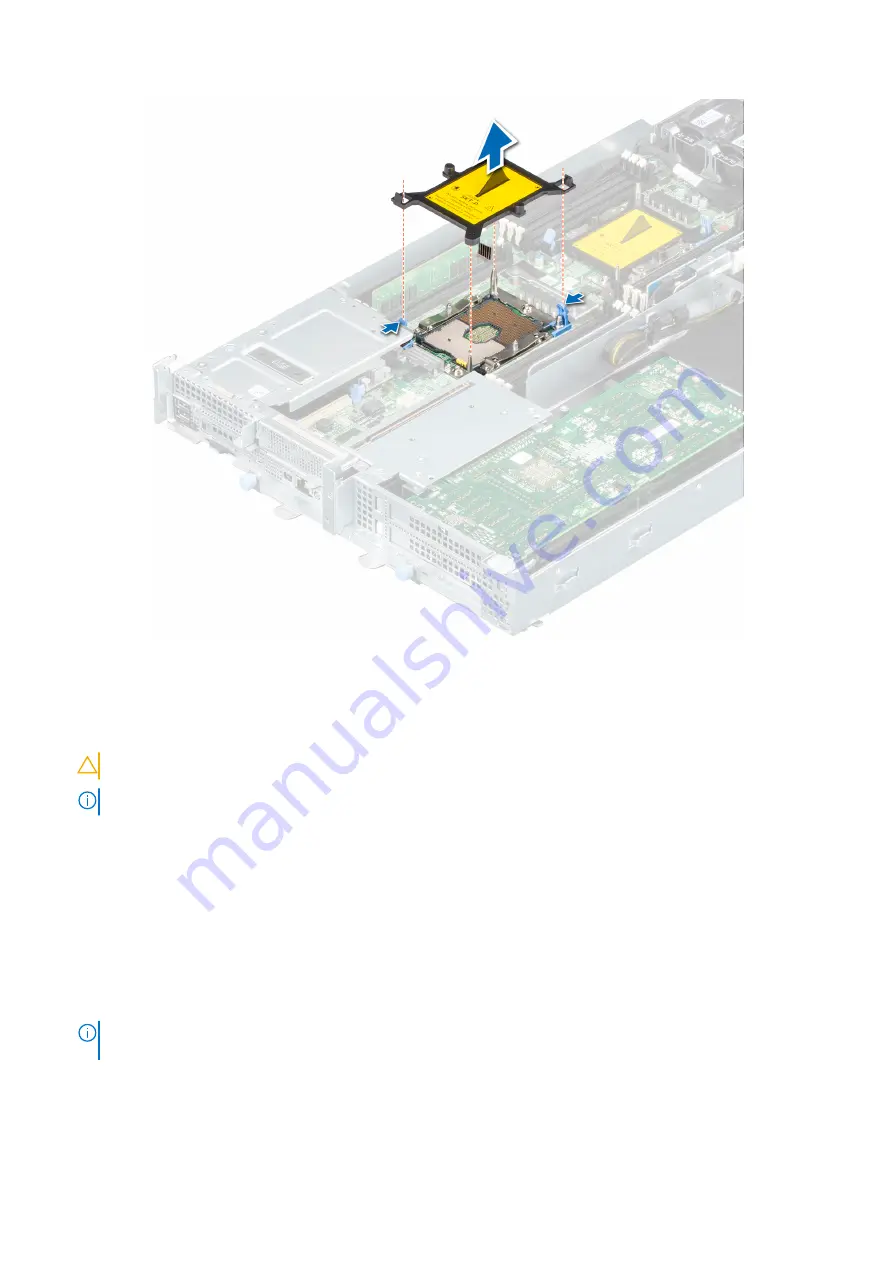
Figure 74. Removing CPU dust cover
Steps
1. Align the pin indicator of the heat sink to the system board and then place the processor and heat sink module (PHM) on the
processor socket.
CAUTION:
To avoid damaging the fins on the heat sink, do not press down on the heat sink fins.
NOTE:
Ensure that the PHM is held parallel to the system board to prevent damaging the components.
2. Push the blue retention clips inward to allow the heat sink to drop into place.
3. Using the Torx #T30 screwdriver, tighten the screws on the heat sink in the order below:
a. Partially tighten the first screw (approximately three turns).
b. Tighten the second screw completely.
c. Return to the first screw and tighten it completely.
If the PHM slips off the blue retention clips when the screws are partially tightened, follow these steps to secure the PHM:
a. Loosen both the heat sink screws completely.
b. Lower the PHM on to the blue retention clips, following the procedure described in step 2.
c. Secure the PHM to the system board, following the replacement instructions listed in this step above.
NOTE:
The processor and heat sink module retention screws should not be tightened to more than 0.13 kgf-m (1.35
N.m or 12 in-lbf).
106
Installing and removing system components
Summary of Contents for EMC PowerEdge XE7440
Page 12: ...System information labels Figure 4 System board connectors 12 PowerEdge XE7440 overview ...
Page 13: ...Figure 5 Express Service Tag PowerEdge XE7440 overview 13 ...
Page 14: ...Figure 6 Memory information 14 PowerEdge XE7440 overview ...
Page 15: ...Figure 7 System tasks PowerEdge XE7440 overview 15 ...


