background image

Installation procedure for SSD

About this task

Installation of the SSD requires removal of the bottom panel, and the SSD bracket is preinstalled in the EGW-5200.

Steps

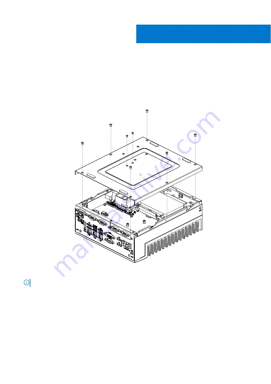
1. Remove the eight screws from the bottom panel of the EGW-5200, as shown in the following figure, and remove the bottom

panel.

Figure 1. Bottom panel screw locations

NOTE:

 If 4G or 5G is installed, you must also remove the remaining four screws.

2. Remove the four screws of the SSD bracket, as shown in the following figure.

I

4

Installation procedure for SSD

Summary of Contents for EMC Edge Gateway 5200

Page 1: ...Dell EMC Edge Gateway 5200 Service Manual January 2022 Rev A00 ...

Page 2: ...ential damage to hardware or loss of data and tells you how to avoid the problem WARNING A WARNING indicates a potential for property damage personal injury or death 2022 Dell Inc or its subsidiaries All rights reserved Dell EMC and other trademarks are trademarks of Dell Inc or its subsidiaries Other trademarks may be trademarks of their respective owners ...

Page 3: ...tion procedure for 2x isolated COM 422 485 or 232 uFM module 20 Part IV Installation procedure for 2x GbE with PoE uFM module 29 Part V Installation procedure for 2x GbE LAN uFM module 38 Part VI Installation procedure for 2x Canbus uFM module 47 Part VII Installation procedure for 8x DI O uFM module 54 Contents Contents 3 ...

Page 4: ...0 Steps 1 Remove the eight screws from the bottom panel of the EGW 5200 as shown in the following figure and remove the bottom panel Figure 1 Bottom panel screw locations NOTE If 4G or 5G is installed you must also remove the remaining four screws 2 Remove the four screws of the SSD bracket as shown in the following figure I 4 Installation procedure for SSD ...

Page 5: ...ng figure Figure 3 SSD mounted to SSD bracket NOTE Four M3 screws are included in the unit package 4 Slide the SSD and SSD bracket assembly into place with the SSD back to the device as shown in the following figure Replace the screws in step 2 to secure the assembly to the motherboard Installation procedure for SSD 5 ...

Page 6: ...Figure 4 SSD assembly installation 5 Reattach the bottom panel See the screw locations in step 1 6 Installation procedure for SSD ...

Page 7: ...the dimensions of the antenna 42 0 0 3 184 0 1 0 38 5 0 5 210 0 1 0 13 0 0 3 13 0 0 3 A A Figure 5 4G 5G LTE antenna dimensions in mm Table 1 Expansion module packing list 4G Item Quantity Notes Screw M3 x 6L 1 Torque required 4 0 kgf cm Screw M3 x 4L 7 Torque required 4 0 kgf cm Standoff H7 8 1 Torque required 4 5 kgf cm Standoff H19 5 2 Torque required 4 5 kgf cm Bracket 1 4G M 2 1 SMA cable 3 A...

Page 8: ...equired 4 5 kgf cm Standoff H19 5 2 Torque required 4 5 kgf cm Bracket 1 5G M 2 1 SMA cable 4 Antenna 4 5G label 1 5G heat sink 1 Thermal pad 1 Steps 1 Remove the eight screws from the bottom panel of the EGW 5200 as shown in the following figure and remove the bottom panel Figure 6 Bottom panel screw locations 2 Remove the screws and nuts from the inside of the bottom panel and side panel as show...

Page 9: ...Figure 7 Bottom panel screw locations Figure 8 Side panel screws Installation procedure for 4G and 5G expansion modules 9 ...

Page 10: ...rubber insert from the ANT1 ANT4 5G only ANT5 and ANT6 antenna holes Figure 10 ANT1 antenna hole in side panel Figure 11 ANT4 ANT5 and ANT6 antenna holes in back panel and side panel 10 Installation procedure for 4G and 5G expansion modules ...

Page 11: ...he flat section of the antenna hole Position the cable connector so that the sheet metal of the panel is between the two washers Figure 12 Align SMA cable with antenna hole Figure 13 Position sheet metal A between SMA cable connector washers B C Figure 14 SMA cables connected Installation procedure for 4G and 5G expansion modules 11 ...

Page 12: ...the following figures Use cable clips to secure the cables Figure 15 4G cable routing Table 3 4G cable routing Antenna Function Cable length cm ANT1 4G Main 10 ANT5 4G GNSS 30 ANT6 4G Auxiliary 30 12 Installation procedure for 4G and 5G expansion modules ...

Page 13: ... 5G cable routing Table 4 5G cable routing Antenna Function Cable length cm ANT1 5G FR1 TX RX 10 ANT4 LTE 5G RX 20 ANT5 LTE 5G RX 30 ANT6 5G FR1 TX RX 30 Installation procedure for 4G and 5G expansion modules 13 ...

Page 14: ...all the 4G or 5G module in the location indicated with a red rectangle in the following figure Figure 18 M 2 module location 7 Apply the thermal pad as shown in the following figure 14 Installation procedure for 4G and 5G expansion modules ...

Page 15: ...Figure 19 Thermal pad 8 Slide the protection bracket of IPEX connectors into position as shown in the following figure Installation procedure for 4G and 5G expansion modules 15 ...

Page 16: ...tandoff as shown in the following figure Figure 21 Standoff installed 10 Assemble the standoffs on the heat sink Screw the standoffs tightly into position as shown in the following figures 16 Installation procedure for 4G and 5G expansion modules ...

Page 17: ...andoff screws assembled 11 To apply the heat sink onto the M 2 module screw the heat sink into position as shown in the following figure then use the screws and nuts to reattach to the side panel Installation procedure for 4G and 5G expansion modules 17 ...

Page 18: ...12 Organize the SMA cables in the chassis to avoid kinks Figure 25 SMA cable organization 13 Use the twelve screws to reattach the bottom panel to the chassis and the heat sink 18 Installation procedure for 4G and 5G expansion modules ...

Page 19: ...Figure 26 Reattach the bottom panel Installation procedure for 4G and 5G expansion modules 19 ...

Page 20: ... kgf cm Cable tie 2 Rubber cap 2 Sheet metal I O panel 1 RS 422 and RS 485 mPCIe 1 Dual port COM cable 1 Cable 1 Cable 1 Cable 1 Table 6 Expansion module packing list for RS 232 Item Quantity Notes Screw M3 x 4L 8 Torque required 4 0 kgf cm Screw M2 5 x 6L 2 Torque required 3 0 kgf cm Standoff H4 8 Torque required 4 5 kgf cm Nut M3 4 Torque required 4 0 kgf cm Cable tie 2 Rubber cap 2 Sheet metal ...

Page 21: ...at sink to the side panel and motherboard as shown in the following figures Figure 28 Heat sink screw locations 3 Remove the screws that secure the mPCIe assembly to the motherboard and disconnect the WiFi cables as shown in the following figure then remove the assembly M 2 to mPCIe adapter board and WiFi card from the motherboard Installation procedure for 2x isolated COM 422 485 or 232 uFM modul...

Page 22: ...llowing figure Figure 30 Disconnect COM port cable 5 Remove the SMA cables from the ANT2 and ANT3 antenna ports as shown in the following figure Figure 31 Remove SMA cables 6 Install screws and nuts to holes previously used to secure the heat sink in the side panel and bottom panel as shown in the following figures 22 Installation procedure for 2x isolated COM 422 485 or 232 uFM module ...

Page 23: ...ews and nuts on bottom panel NOTE Reuse screws removed from this step 7 Remove the screws of the front I O panel as shown in the following figure Remove the 4 port COM cable from the front I O panel Installation procedure for 2x isolated COM 422 485 or 232 uFM module 23 ...

Page 24: ...ont I O panel with the port labeled A to COM1 and B to COM2 then connect the other end of the cable to the motherboard header Figure 35 Connect new COM ports to I O panel Figure 36 Connect dual port COM cable to motherboard header 24 Installation procedure for 2x isolated COM 422 485 or 232 uFM module ...

Page 25: ...el Isolated COM B RS 485 A Label Isolated COM A RS 485 B Label Isolated COM B RS 232 Isolated COM A RS 232 Isolated COM B 10 Secure the Isolated COM I O panel to the front I O panel Use the two screws to the sides of the Isolated COM I O panel and the two screws on the bottom edge of the chassis as shown in the following figure Figure 38 Isolated COM I O panel installed on front I O panel 11 Insta...

Page 26: ...0 Isolated COM 232 mPCIe installed on motherboard 12 Connect the cables from the Isolated COM ports to the Isolated COM mPCIe module Use a cable tie as shown with a red circle in the following figure 26 Installation procedure for 2x isolated COM 422 485 or 232 uFM module ...

Page 27: ...rts to Isolated COM 232 mPCIe module with cable tie COM A CN1 COM B CN2 13 Use the screws to reattach the bottom panel See the screw locations in step 1 14 Insert the rubber caps into the antenna holes as shown in the following figure Installation procedure for 2x isolated COM 422 485 or 232 uFM module 27 ...

Page 28: ...Figure 43 Antenna hole caps 28 Installation procedure for 2x isolated COM 422 485 or 232 uFM module ...

Page 29: ...x 4L 14 Torque required 4 0 kgf cm Screw M3 x 5L 1 Torque required 4 0 kgf cm Standoff H4 4 Torque required 4 5 kgf cm Nut M3 4 Torque required 4 0 kgf cm Screw M2 5 x 6L 2 Torque required 3 0 kgf cm Cable tie 2 Rubber cap 2 Cable clip 1 Sheet metal I O panel 1 Bracket 1 PoE PCBA 1 PoE mPCIe 1 Dual port COM cable 1 Cable 2 Thermal pad 1 Steps 1 Remove the eight screws from the bottom panel of the ...

Page 30: ...f the heat sink to the side panel and motherboard as shown in the following figures Figure 45 Heat sink screw locations 3 Remove the screws that secure the mPCIe assembly to the motherboard and disconnect the WiFi cables as shown in the following figure then remove the assembly M 2 to mPCIe adapter board and WiFi card from the motherboard 30 Installation procedure for 2x GbE with PoE uFM module ...

Page 31: ... the following figure Figure 47 Disconnect COM port cable 5 Remove the SMA cables from the ANT2 and ANT3 antenna ports as shown in the following figure Figure 48 Remove SMA cables 6 Install screws and nuts to holes previously used to secure the heat sink in the side panel and bottom panel as shown in the following figures Installation procedure for 2x GbE with PoE uFM module 31 ...

Page 32: ...nd nuts on bottom panel NOTE Reuse screws removed from Step 1 Nuts are included in the kit 7 Remove the screws of the front I O panel as shown in the following figure Remove the 4 port COM cable from the front I O panel 32 Installation procedure for 2x GbE with PoE uFM module ...

Page 33: ... the front I O panel with the port labeled A to COM1 and B to COM2 then connect the other end of the cable to the motherboard header Figure 52 Connect new COM ports to I O panel Figure 53 Connect dual port COM cable to motherboard header Installation procedure for 2x GbE with PoE uFM module 33 ...

Page 34: ... uFM board to the I O panel that is included in the Expansion Module using the two screws and the nut and washer of the DC IN jack as shown in the following figures Figure 55 GbE with PoE I O panel Figure 56 GbE with PoE uFM module with I O panel 11 Secure the bracket to the motherboard using four screws as shown in the following figure 34 Installation procedure for 2x GbE with PoE uFM module ...

Page 35: ...the uFM module to the bracket and device chassis and secure the GbE with PoE I O panel to the front I O panel as shown in the following figures Figure 58 uFM module secured to bracket and chassis Installation procedure for 2x GbE with PoE uFM module 35 ...

Page 36: ...le clip on bracket 14 Secure the mPCIe LAN board to the motherboard as shown in the following figure Figure 61 mPCIe LAN board secured to motherboard 15 Connect the LAN cables from the GbE with PoE module to the mPCIe LAN board Use cable ties as shown with red circles in the following figure 36 Installation procedure for 2x GbE with PoE uFM module ...

Page 37: ...d with cable ties 16 Use the screws to reattach the bottom panel See the screw locations in step 1 17 Insert the rubber caps into the antenna holes as shown in the following figure Figure 63 Antenna hole caps Installation procedure for 2x GbE with PoE uFM module 37 ...

Page 38: ...ew M3 x 4L 14 Torque required 4 0 kgf cm Screw M3 x 5L 1 Torque required 4 0 kgf cm Standoff H4 4 Torque required 4 5 kgf cm Nut M3 4 Torque required 4 0 kgf cm Screw M2 5 x 6L 2 Torque required 3 0 kgf cm Cable tie 2 Rubber cap 2 Cable clip 1 Sheet metal I O panel 1 Bracket 1 LAN PCBA 1 LAN mPCIe 1 Dual port COM cable 1 LAN cable 2 Steps 1 Remove the eight screws from the bottom panel of the EGW ...

Page 39: ... of the heat sink to the side panel and motherboard as shown in the following figures Figure 65 Heat sink screw locations 3 Remove the screws that secure the mPCIe assembly to the motherboard and disconnect the WiFi cables as shown in the following figure then remove the assembly M 2 to mPCIe adapter board and WiFi card from the motherboard Installation procedure for 2x GbE LAN uFM module 39 ...

Page 40: ... in the following figure Figure 67 Disconnect COM port cable 5 Remove the SMA cables from the ANT2 and ANT3 antenna ports as shown in the following figure Figure 68 Remove SMA cables 6 Install screws and nuts to holes previously used to secure the heat sink in the side panel and bottom panel as shown in the following figures 40 Installation procedure for 2x GbE LAN uFM module ...

Page 41: ... and nuts on bottom panel NOTE Reuse screws removed from step 1 Nuts are included in the kit 7 Remove the screws of the front I O panel as shown in the following figure Remove the 4 port COM cable from the front I O panel Installation procedure for 2x GbE LAN uFM module 41 ...

Page 42: ... to the front I O panel with the port labeled A to COM1 and B to COM2 then connect the other end of the cable to the motherboard header Figure 72 Connect new COM ports to I O panel Figure 73 Connect dual port COM cable to motherboard header 42 Installation procedure for 2x GbE LAN uFM module ...

Page 43: ...two screws on the panel as shown in the following figure Figure 74 GbE LAN ports installed on GbE LAN I O panel 10 Install the bracket on the motherboard as shown in the following figure Figure 75 Bracket installed Installation procedure for 2x GbE LAN uFM module 43 ...

Page 44: ...odule to the bracket as shown in the following figure Figure 76 GbE LAN module installed 12 Install the GbE LAN mPCIe module on the motherboard Use the two screws in the corners of the module as shown in the following figure Figure 77 GbE LAN mPCIe installed on motherboard 13 Attach the cable clip to the bracket as shown in the following figure 44 Installation procedure for 2x GbE LAN uFM module ...

Page 45: ...hown with red circles in the following figure Figure 79 Cables from uFM to mPCIe module with cable ties 15 Use the screws to reattach the bottom panel See the screw locations in step 1 16 Insert the rubber caps into the antenna holes as shown in the following figure Installation procedure for 2x GbE LAN uFM module 45 ...

Page 46: ...Figure 80 Antenna hole caps 46 Installation procedure for 2x GbE LAN uFM module ...

Page 47: ... M3 x 4L 8 Torque required 4 0 kgf cm Standoff H4 8 Torque required 4 5 kgf cm Screw M2 5 x 6L 2 Torque required 3 0 kgf cm Nut M3 4 Torque required 4 0 kgf cm Cable tie 2 Rubber cap 2 Sheet metal I O panel 1 Canbus mPCIe 1 Dual port COM cable 1 Cable 2 Steps 1 Remove the eight screws from the bottom panel of the EGW 5200 as shown in the following figure and remove the bottom panel Figure 81 Botto...

Page 48: ...ns 3 Remove the screws that secure the mPCIe assembly to the motherboard and disconnect the WiFi cables as shown in the following figure then remove the assembly M 2 to mPCIe adapter board and WiFi card from the motherboard Figure 83 Motherboard screws and WiFi cable connectors 4 Disconnect the 4 port COM cable from the motherboard header and from the front I O panel and cut the cable tie as shown...

Page 49: ... shown in the following figure Figure 85 Remove SMA cables 6 Install screws and nuts to holes previously used to secure the heat sink in the side panel and bottom panel as shown in the following figures Figure 86 Install screws and nuts on side panel Installation procedure for 2x Canbus uFM module 49 ...

Page 50: ... as shown in the following figure Remove the 4 port COM cable from the front I O panel Figure 88 I O panel screw locations 8 Install the new dual port COM cable included Connect to the front I O panel with the port labeled A to COM1 and B to COM2 then connect the other end of the cable to the motherboard header 50 Installation procedure for 2x Canbus uFM module ...

Page 51: ...the four screws on the panel as shown in the following figure Figure 91 Canbus ports installed on Canbus I O panel 10 Secure the Canbus I O panel to the front I O panel Use the two screws to the sides of the Canbus I O panel and the two screws on the bottom edge of the chassis as shown in the following figure Installation procedure for 2x Canbus uFM module 51 ...

Page 52: ... the two screws in the corners of the module as shown in the following figure Figure 93 Canbus mPCIe installed on motherboard 12 Connect the cables from the Canbus ports to the Canbus mPCIe module Use a cable tie as shown with a red circle in the following figure 52 Installation procedure for 2x Canbus uFM module ...

Page 53: ...th cable tie 13 Use the screws to reattach the bottom panel See the screw locations in step 1 14 Insert the rubber caps into the antenna holes as shown in the following figure Figure 95 Antenna hole caps Installation procedure for 2x Canbus uFM module 53 ...

Page 54: ...m Screw M2 5 x 6L 2 Torque required 3 0 kgf cm Screw M3 x 6L 2 Torque required 4 0 kgf cm Standoff H4 6 Torque required 4 5 kgf cm Standoff H7 2 Torque required 4 5 kgf cm Nut M3 4 Torque required 4 0 kgf cm Cable tie 2 Rubber cap 2 Sheet metal I O panel 1 Bracket 1 DI O PCBA 1 Dual port COM cable 1 DI O cable 1 Steps 1 Remove the eight screws from the bottom panel of the EGW 5200 as shown in the ...

Page 55: ...crews 2 Remove the screws of the front I O panel as shown in the following figure Figure 97 I O panel screw locations 3 Disconnect the 4 port COM cable from the motherboard header and from the front I O panel and cut the cable tie as shown in the following figure Installation procedure for 8x DI O uFM module 55 ...

Page 56: ...d B to COM2 then connect the other end of the cable to the motherboard header Figure 99 Connect new COM ports to I O panel Figure 100 Connect dual port COM cable to motherboard header 5 Secure the DI O uFM module to the DI O front panel Use the two screws on the panel as shown in the following figure 56 Installation procedure for 8x DI O uFM module ...

Page 57: ...all the bracket on the motherboard as shown in the following figure Figure 102 Bracket installed 7 Install two standoffs on the bracket as shown in the following figure Figure 103 Standoffs installed on bracket Installation procedure for 8x DI O uFM module 57 ...

Page 58: ... two screws to secure the module to the standoffs on the bracket as shown in the following figure Figure 104 DI O module installed 9 Connect the DI O cable Use a cable tie as shown with a red circle in the following figure Figure 105 DI O cable with cable tie Pin mappings are shown in the following figure and table 58 Installation procedure for 8x DI O uFM module ...

Page 59: ...0 2 DI1_L 11 DI1_H 20 DO1 3 DI2_L 12 DI2_H 21 DO2 4 DI3_L 13 DI3_H 22 DO3 5 DI4_L DI5_L 14 DI4_H 23 DO4 6 GND_DIO 15 DI5_H 24 DO5 7 DI6_L DI7_L 16 DI6_H 25 DO6 8 VDIO_EXT 17 DI7_H 26 DO7 9 5V0_DIO 18 GND_DIO 10 Use the screws to reattach the bottom panel See the screw locations in step 1 Installation procedure for 8x DI O uFM module 59 ...

Reviews: