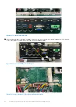
9. Secure the Isolated COM ports to the Isolated COM I/O panel. Use the four screws on the panel, as shown in the following
figure.
Figure 37. COM ports installed on Isolated COM I/O panel
Use the following table to configure the Isolated COM ports.
Table 7. Isolated COM port mappings
Cable > Port
Cable > Port
RS-422 A Label > Isolated COM A
RS-422 B Label > Isolated COM B
RS-422 A Label > Isolated COM A
RS-485 A Label > Isolated COM B
RS-485 A Label > Isolated COM A
RS-485 B Label > Isolated COM B
RS-232 > Isolated COM A
RS-232 > Isolated COM B
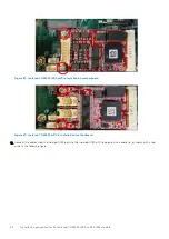
10. Secure the Isolated COM I/O panel to the front I/O panel. Use the two screws to the sides of the Isolated COM I/O panel
and the two screws on the bottom edge of the chassis, as shown in the following figure.
Figure 38. Isolated COM I/O panel installed on front I/O panel
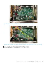
11. Install the Isolated COM mPCIe module on the motherboard. Use the two screws in the corners of the module, as shown in
the following figure.
Installation procedure for 2x isolated COM 422/485 or 232 uFM module
25


