background image

NOTE:

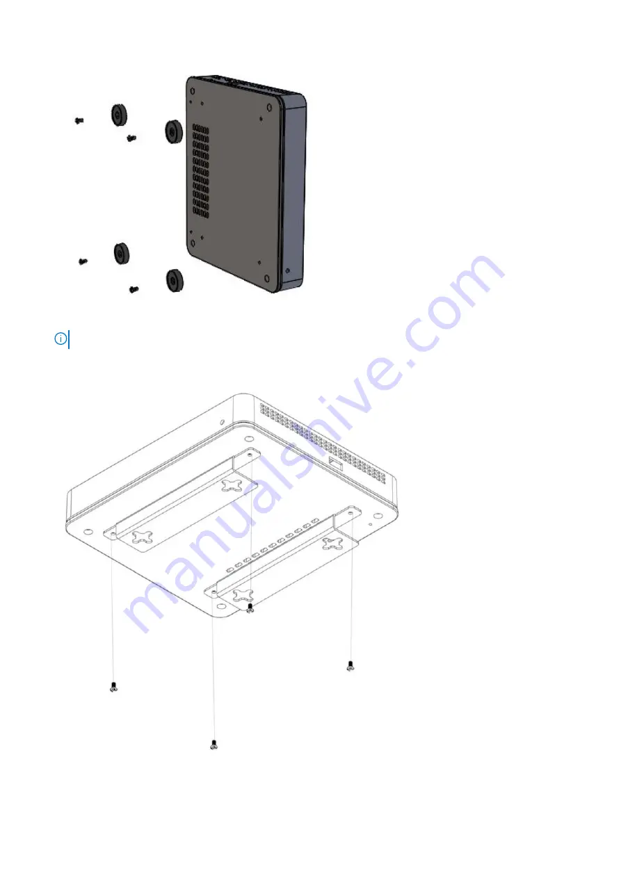
 The rubber feet must be removed because they share the same screw holes with the wall mount brackets.

2. Using a torque screwdriver, attach the included wall mount brackets to the platform using the four M3 screws that mounted

the rubber feet.

3. Anchor the screws into the wall surface.
4. Slide the cross-shaped cutouts of the wall. mount brackets into the screws that are anchored to the wall

12

Edge 510 LTE installation

Summary of Contents for EMC Edge 510 LTE

Page 1: ...Dell EMC Edge 510 LTE Installation guide February 2021 Rev A01 ...

Page 2: ...tial damage to hardware or loss of data and tells you how to avoid the problem WARNING A WARNING indicates a potential for property damage personal injury or death 2016 2020 Dell Inc or its subsidiaries All rights reserved Dell EMC and other trademarks are trademarks of Dell Inc or its subsidiaries Other trademarks may be trademarks of their respective owners ...

Page 3: ...ter 4 Edge 510 LTE installation 10 Unpack 10 SIM card 10 Desktop mount 11 Wall mount 11 Rack mount 13 Platform power on 14 Platform setup 14 Configure Edge 510 LTE activation 17 Chapter 5 Specifications 19 Chassis physical design 19 IEEE standards 20 Agency compliance 20 USA Federal Communications Commission statement 20 FCC caution 20 Industry Canada Statement 20 Brasil Aviso da Anatel 22 Europea...

Page 4: ...ptical transceivers which comply with the limits of Class 1 laser radiation Figure 1 Class 1 laser product tag NOTE When no cable is connected visible and invisible laser radiation may emit from the aperture of the optical transceiver ports Avoid exposure to laser radiation Do not stare into open apertures NOTE Read this guide before unpacking the device For unpacking instructions see Unpack Regul...

Page 5: ...prise wide configuration real time monitoring and orchestrates the data flow into and through the SD WAN overlay network NOTE To search for drivers and downloads go to www dell com drivers Topics Introduction Features Physical dimensions LEDs Edge 510 LTE configuration Prerequisites Introduction The Dell EMC Edge 510 LTE is a high performance purpose built platform It is a fixed desktop form facto...

Page 6: ...external PSU on top of the Edge 510 LTE platform Desktop mount with rubber feet and wall mount accessories included Optional rack mount accessory available Physical dimensions 8 1 in x 7 1 in x 1 57 in W x D x H 20 6 cm x 18 0 cm x 4 0 cm W x D x H LEDs The Dell EMC Edge 510 LTE has a service indicator LED display on the front of the platform This indicator displays the status of the platform the ...

Page 7: ... Link down Edge 510 LTE configuration Two core CPU Four 1 GbE networking ports One Mini USB 2 0 console port Two USB 2 0 Type A AC power supply No fan Airflow on sides and back Prerequisites The following is a list of components that are required for successful platform installation NOTE For detailed installation instructions see Site preparations and Site installation Dell EMC Edge 510 LTE platfo...

Page 8: ...red earth ground socket outlet Environmental platform location continuous temperature range is 0 C to 40 C 32 F to 104 F Operating humidity 5 to 85 RH noncondensing continuously 5 to 90 RH noncondensing Short term 1 of operational hour per year In a dry clean well ventilated and temperature controlled room away from heat sources such as hot air vents or direct sunlight Away from sources of severe ...

Page 9: ...s If you do not install your Edge 510 LTE platform and components immediately properly store the platform and all components using these guidelines Storage location temperature must remain constant The storage range is from 40 C to 70 C 40 to 158 F Store on a dry surface or floor away from direct sunlight heat and air conditioning ducts Store in a dust free environment NOTE ESD damage can occur wh...

Page 10: ...ntainer and immediately report any evidence of damage When unpacking the platform ensure that the following items are included AC power cable NOTE Power cable is in a separate box from the unit Two RJ45 cables One Dell EMC Edge 510 LTE platform Two antennas AC to DC power adapter Wall mount brackets Dell EMC Edge 510 LTE Set Up Guide Safety and Regulatory Information Warranty and Support Informati...

Page 11: ...0 LTE includes two wall mount brackets WARNING When mounting the Edge 510 platform to the wall face the Ethernet ports up towards the ceiling and the system status LED panel facing the floor NOTE Ensure that the platform is in a well ventilated environment with clearance around the air vents Wall mount brackets have a cross shaped cutout NOTE Before mounting the unit to the wall verify that the wa...

Page 12: ...ing a torque screwdriver attach the included wall mount brackets to the platform using the four M3 screws that mounted the rubber feet 3 Anchor the screws into the wall surface 4 Slide the cross shaped cutouts of the wall mount brackets into the screws that are anchored to the wall 12 Edge 510 LTE installation ...

Page 13: ...e dual rackmount tray separately You must have a torque screwdriver to complete this installation NOTE Verify that you torque to 5 lb in when driving the screws into the bracket and platform NOTE Remove the rubber feet from the bottom of the platform when mounting on a rack mount tray NOTE Ensure that the platform is in a well ventilated environment with clearance around the air vents 1 Place one ...

Page 14: ...ing The ambient temperature around the platform which may be higher than the room temperature is within the limits that are specified for the Edge 510 LTE For more information see Specifications There is no source of heat near the unit NOTE If components are mishandled ESD damage can occur Always wear an ESD preventive wrist or heel ground strap when handling the platform and components Platform s...

Page 15: ...Edge 510 LTE and secure it by turning the lock screw Connect the AC power cable to the power adapter and plug the other end of AC power cable into AC power outlet NOTE Connect the power adapter to a properly wired earth ground AC power outlet 2 Attach either the GE3 or GE4 1 Gb WAN Ethernet port to an available Internet connection NOTE Use ONLY the GE3 or GE4 1 Gb WAN Ethernet ports for Internet c...

Page 16: ...tative 5 Follow the instructions in the email to complete the Edge 510 LTE activation NOTE Keep your email application open during activation Connect your device to power and any either ethernet cables or USB modems Find and connect to the Wi Fi network that looks like velocloud followed by 3 more letters numbers e g velocloud xyz where xyz is the last three digits of service tag of the Edge510 un...

Page 17: ...ur SD WAN Orchestrator account to request an activation key and configure the new Edge 510 LTE unit Assign an activation key 1 Select the Edge Overview tab 2 Select Send Activation Email 3 Enter a valid email address in the activation display window that is sent to a site contact This Send Activation Email wizard includes sample activation instructions in the message body that is sent to the Site ...

Page 18: ...il are for cellular settings for example SIM PIN Network APN and Username NOTE Run the LTE Modem Information diagnostic test for troubleshooting purposes for a configured Edge 510 LTE device The LTE Modem Information diagnostic test gathers diagnostic information like signal strength and connection information NOTE Check your email for the activation invitation 18 Edge 510 LTE installation ...

Page 19: ...ower adapter weight 2 29 lbs 0 91 Kg AC power input 100 VAC 240 VAC 50 60 Hz AC maximum current draw per system 100 VAC 1 5 A 240 VAC 0 9 A Typical power consumption 15 W Maximum power consumption 28 W RoHS information Go to Restricted Material Compliance Table 3 Edge 510 LTE temperatures Feature Specification Operating temperature 0 C 40 C 32 F 104 F Storage temperature 40 C 70 C 40 F to 158 F Op...

Page 20: ...e radio frequency energy and if not installed and used in accordance with the instructions may cause harmful interference to radio communications However there is no guarantee that interference will not occur in a particular installation If this equipment does cause harmful interference to radio or television reception which can be determined by turning the equipment off and on the user is encoura...

Page 21: ...g in conjunction with any other antenna or transmitter except tested built in radios Cet appareil et son antenne ne doivent pas être situés ou fonctionner en conjonction avec une autre antenne ou un autre émetteur exception faites des radios intégrées qui ont été testées Radiation Exposure Statement This equipment complies with IC radiation exposure limits set forth for an uncontrolled environment...

Page 22: ...ility Low Voltage Directive EU R TTE The following is a list and reference to the relevant Harmonised Standards used EN 55032 2015 EN 55024 2010 EN 301 489 1 V2 2 0 EN 301 489 17 V3 2 0 EN 300 328 V2 1 1 EN 301 893 V2 1 1 EN 302 502 V2 1 1 EN 62311 2008 EN 60950 1 2006 A11 2009 A1 2010 A12 2011 A2 2013 EN 301 908 13 V11 1 2 The CE testing and RED GAP analysis was performed by a third party test la...

Page 23: ...return and recycling of used appliances as applicable throughout the European Union This label is applied to various products to indicate that the product is not to be thrown away but rather reclaimed upon end of life per this Directive Figure 3 The European WEEE symbol In accordance with the European WEEE Directive electrical and electronic equipment EEE is to be collected separately and to be re...

Page 24: ...age scroll down to the bottom of the web page and select your country from the drop down menu To obtain product specific information enter the 7 character service tag or the 11 digit express service code of your appliance and click submit To view the appliance service tag or express service code pull out the luggage tag on the upper right side of the appliance To receive more technical support cli...

Reviews: