background image

5. Close the 

front panel door

.

6. Install the:

a.

intrusion switch

b.

front bezel

c.

side cover

7. Follow the procedure in 

After working inside your computer

.

Optional VGA module

Removing optional VGA module

1. Follow the procedure in 

Before working inside your computer

.

2. Remove the:

a.

Side cover

b.

Front bezel

3. Open the 

front panel door

4. Remove the 

system fan

.

5. To remove the optional VGA module:

a. Remove the two (M3X3) screws that secure the optional VGA module to the system.

56

Disassembly and reassembly

Summary of Contents for D18M

Page 1: ...OptiPlex XE3 Tower Service Manual Regulatory Model D18M Regulatory Type D18M005 August 2021 Rev A01 ...

Page 2: ...14 Front panel door 15 Opening the front panel door 15 Closing front panel door 15 3 5 inch hard drive assembly 16 Removing 3 5 inch hard drive assembly 16 Installing 3 5 inch hard drive assembly 17 3 5 inch hard drive 19 2 5 inch hard drive assembly 20 Removing the 2 5 inch drive assembly 20 Installing the 2 5 inch drive assembly 20 2 5 inch hard drive 21 Optical drive 22 Removing optical drive 2...

Page 3: ... Installing heatsink assembly 51 Processor 52 Removing processor 52 Installing processor 53 System fan 54 Removing system fan 54 Installing system fan 55 Optional VGA module 56 Removing optional VGA module 56 Installing optional VGA module 57 System board 58 Removing system board 58 Installing the system board 61 Chapter 3 Drivers and downloads 64 Chapter 4 System setup 65 Boot Sequence 65 Navigat...

Page 4: ... Chapter 5 Troubleshooting 77 Enhanced Pre Boot System Assessment ePSA diagnostics 77 Running the ePSA Diagnostics 77 Diagnostics 77 Backup media and recovery options 79 Recovering the operating system 79 Battery status lights 80 Chapter 6 Getting help and contacting Dell 81 4 Contents ...

Page 5: ...tial damage to hardware or loss of data and tells you how to avoid the problem WARNING A WARNING indicates a potential for property damage personal injury or death 2017 2021 Dell Inc or its subsidiaries All rights reserved Dell EMC and other trademarks are trademarks of Dell Inc or its subsidiaries Other trademarks may be trademarks of their respective owners ...

Page 6: ...technical assistance team Damage due to servicing that is not authorized by Dell is not covered by your warranty See the safety instructions that is shipped with the product or at www dell com regulatory_compliance CAUTION Before touching anything inside your computer ground yourself by touching an unpainted metal surface such as the metal at the back of the computer While you work periodically to...

Page 7: ...ponents especially sensitive components such as expansion cards processors memory DIMMs and system boards Very slight charges can damage circuits in ways that may not be obvious such as intermittent problems or a shortened product life span As the industry pushes for lower power requirements and increased density ESD protection is an increasing concern Due to the increased density of semiconductor...

Page 8: ...st plug the wrist strap s bonding wire into the tester while it is strapped to your wrist and push the button to test A green LED is lit if the test is successful a red LED is lit and an alarm sounds if the test fails Insulator Elements It is critical to keep ESD sensitive devices such as plastic heat sink casings away from internal parts that are insulators and often highly charged Working Enviro...

Page 9: ...onnect any external devices peripherals or cables you removed before working on your computer 3 Replace any media cards discs or any other parts that you removed before working on your computer 4 Connect your computer and all attached devices to their electrical outlets 5 Turn on your computer Turning off your computer Windows 10 CAUTION To avoid losing data save and close all open files and exit ...

Page 10: ...tray or loose screws inside your computer may severely damage your computer 1 Replace all screws and ensure that no stray screws remain inside your computer 2 Connect any external devices peripherals or cables you removed before working on your computer 3 Replace any media cards discs or any other parts that you removed before working on your computer 4 Connect your computer and all attached devic...

Page 11: ...r Power button Heat sink fan Coin cell battery Heat sink Processor System fan Optional VGA module System board Side cover Removing side cover 1 Follow the procedure in Before working inside your computer 2 To release the side cover a Slide the blue tab to release the side cover from the computer 1 b Slide the side cover toward the back of the computer 2 c Lift the side cover to remove it from the ...

Page 12: ...de cover 1 Place the side cover on the computer and slide the side cover forward 1 2 Slide the side cover until the click sound and the blue tab secures the side cover to the computer 2 12 Disassembly and reassembly ...

Page 13: ...the procedure in Before working inside your computer 2 Remove the side cover 3 To remove the front bezel a Lift the tabs to release the front bezel from the chassis 1 b Push the front bezel away from the chassis 2 c Pull the front bezel to release it from the chassis 3 Disassembly and reassembly 13 ...

Page 14: ...the front bezel to align the tab holders on the chassis 2 Slide and press the front bezel until the tabs click in place 3 Install the side cover 4 Follow the procedure in After working inside your computer 14 Disassembly and reassembly ...

Page 15: ...CAUTION The front panel door opens only to a limited extent See the printed image on the front panel door for the maximum permissible level 3 Pull the front panel door to open it Closing front panel door 1 Push the front panel door on the computer and press the side cover forward until the panel door clicks into place Disassembly and reassembly 15 ...

Page 16: ...rive assembly 1 Follow the procedure in Before working inside your computer 2 Remove the a side cover b front bezel 3 To remove the hard drive assembly a Disconnect the hard drive assembly cables from the connectors on the hard drive NOTE Ensure to remove the SATA blue cable first to ease in removing the hard drive data cable 16 Disassembly and reassembly ...

Page 17: ...e assembly 1 c Press the blue tab 2 and pull the hard drive assembly out of the computer 3 Installing 3 5 inch hard drive assembly 1 Insert the hard drive assembly into the slot on the computer until it clicks into place 1 Disassembly and reassembly 17 ...

Page 18: ... the hard drive assembly 2 3 Connect the SATA cable and the power cable to the connectors on the hard drive 4 Install the a front bezel b side cover 5 Follow the procedure in After working inside your computer 18 Disassembly and reassembly ...

Page 19: ...n 25 to avoid damage to the tabs b Pull the hard drive out of the hard drive bracket c Lift the hard drive out of the hard drive bracket 2 Installing the 3 5 inch hard drive into the hard drive bracket 1 Align the hard drive to the side of the hard drive bracket and pull the other end tabs to insert the pins on the bracket into the hard drive 1 2 Insert the hard drive into the hard drive bracket a...

Page 20: ...assembly cables from the connectors on the drive 1 b Press the blue tabs on both sides 2 and pull the drive assembly out of the computer 3 NOTE Gently press the blue tabs to avoid damage to the plastic tabs Installing the 2 5 inch drive assembly 1 Insert the drive assembly into the slot on the computer and press until it clicks into place 1 2 2 Connect the SATA cable and the power cable to the con...

Page 21: ...2 5 inch drive from the drive bracket 1 Follow the procedure in Before Working Inside Your Computer 2 Remove the a side cover b front bezel c 2 5 inch drive assembly 3 To remove the drive a Pull one side of the drive bracket to disengage the pins on the bracket from the slots on the drive 1 b Lift the drive out of the drive bracket 2 Disassembly and reassembly 21 ...

Page 22: ...bezel c cover 4 Follow the procedure in After working inside your computer Optical drive Removing optical drive 1 Follow the procedure in Before working inside your computer 2 Remove the a side cover b front bezel 3 Open the front panel door 4 To remove the optical drive assembly a Disconnect the data cable and power cable from the connectors on the optical drive 1 NOTE Ensure to unroute the cable...

Page 23: ...c Press the blue release tab 1 and slide the optical drive out of the computer 2 Disassembly and reassembly 23 ...

Page 24: ...Installing optical drive 1 Insert the optical drive into the optical drive bay until the blue release tab clicks into place 24 Disassembly and reassembly ...

Page 25: ...2 Open the front panel door 2 3 Route the data cable and power cable under the drive cage 4 Connect the data cable and power cable to the connectors on the optical drive 3 Disassembly and reassembly 25 ...

Page 26: ...g M 2 PCle SSD optional 1 Follow the procedure in Before working inside your computer 2 Remove the a side cover b front bezel 3 Open the front panel door 4 To remove the M 2 PCIe SSD a Remove the screw that secures the M 2 PCIe SSD to the system board 1 b Slide out the M 2 PCIe SSD from the connector on the system board 2 26 Disassembly and reassembly ...

Page 27: ...Installing M 2 PCle SSD 1 Slide out the M 2 PCIe SSD from the connector on the system board 1 2 Replace the screw that secures the M 2 PCIe SSD to the system board 2 Disassembly and reassembly 27 ...

Page 28: ...ocedure in Before working inside your computer 2 Remove the a side cover b front bezel 3 Open the front panel door 4 To remove the SD card reader a Disconnect the SD card reader cable from the connector on the system board 1 b Remove the screw that secures the SD card reader to the front panel door 2 c Lift the SD card reader out of the computer chassis 3 28 Disassembly and reassembly ...

Page 29: ...the SD card reader into the slot on the front panel door 1 2 Tighten the screw to secure the SD card reader to the front panel door 2 3 Connect the SD card reader cable to the connector on the system board 3 Disassembly and reassembly 29 ...

Page 30: ...ure in Before working inside your computer 2 Remove the a side cover b front bezel 3 Open the front panel door 4 To remove the memory module a Push the memory module retention tabs on both sides of the memory module 1 b Pull the memory module from the memory module connector on the system board 2 NOTE Follow the step 4a 4b to remove the other memory modules 30 Disassembly and reassembly ...

Page 31: ...tch on the memory module with the tab on the memory module connector 2 Insert the memory module into the memory module socket 1 3 Press the memory module until the memory module retention tabs click into place 2 Disassembly and reassembly 31 ...

Page 32: ...on card optional 1 Follow the procedure in Before working inside your computer 2 Remove the a side cover b front bezel 3 Open the front panel door 4 To remove the PCIe expansion card a Pull the blue release tab that secures the PCIe expansion card to the system board 1 b Pull the card retention latch and lift the PCIe expansion card from the connector on the system board 2 3 32 Disassembly and rea...

Page 33: ...t of the computer 5 Repeat the steps to remove any additional PCle expansion card Installing PCIe expansion card 1 Insert the M 2 PCle Card to the connector and push the PCle Card to secure the card with the connector 1 2 Release the card retention latch to secure the PCle expansion card 2 Disassembly and reassembly 33 ...

Page 34: ...or PSU 1 Follow the procedure in Before working inside your computer 2 Remove the a side cover b front bezel 3 Open the front panel door 4 To release the PSU a Press the latch and disconnect the PSU cables from the connectors on the system board 1 b Unroute the PSU cable from the retention clip to release the cable 2 3 4 5 c Press the latch and disconnect the cables from the connector on the syste...

Page 35: ...5 To remove the PSU a Remove the screw 3 to release the PSU from the computer chassis 1 b Press the release tab 2 c Slide and lift the PSU away from the computer 3 Disassembly and reassembly 35 ...

Page 36: ...Installing power supply unit or PSU 1 Insert the PSU into the PSU slot and slide it toward the back of the computer until it clicks into place 1 2 36 Disassembly and reassembly ...

Page 37: ...the screws 3 to secure the PSU to the computer chassis 3 3 Route the PSU cables through the retention clips 2 3 4 5 4 Connect the PSU cables to the connectors on the system board 1 6 Disassembly and reassembly 37 ...

Page 38: ...orking inside your computer 2 Remove the a side cover b front bezel 3 Open the front panel door 4 To remove the intrusion switch a Press the latch and disconnect the intrusion switch cable from the connector on the system board and pull the cable 1 b Unroute the intrusion switch cable from the fan grommet 2 c Slide the intrusion switch and push it to remove from the computer 3 38 Disassembly and r...

Page 39: ...ntrusion switch and slide the switch into the slot on the computer chassis 1 2 Route the intrusion switch cable through the fan grommet 2 3 Connect the intrusion switch cable to the connector on the system board 3 Disassembly and reassembly 39 ...

Page 40: ... Removing speaker 1 Follow the procedure in Before working inside your computer 2 Remove the a side cover b front bezel 3 Open the front panel door 4 To remove the speaker a Disconnect the speaker cable from the connector on the system board 1 b Press the release tabs 2 and slide the speaker out of the slot 3 40 Disassembly and reassembly ...

Page 41: ...Installing speaker 1 Insert the speaker into the slot 1 and slide it until it clicks into place 2 2 Connect the speaker cable to the connector on the system board 3 Disassembly and reassembly 41 ...

Page 42: ...computer 2 Remove the a side cover b front bezel 3 Open the front panel door 4 To release the power switch a Pull the socket to disconnect the power switch cable from the system board 1 b Unroute the power switch cable through the retention clip 2 c Press the release tabs using a plastic scribe and slide the power switch out from the front of the computer 3 d Close the front panel door 4 42 Disass...

Page 43: ...5 Pull the power switch out from the computer Disassembly and reassembly 43 ...

Page 44: ...Installing power button 1 Insert the power switch into the slot from the front of the computer 44 Disassembly and reassembly ...

Page 45: ...Press the power switch to the slot on the computer chassis 2 4 Route the power switch cable through the retention clip 3 5 Align the cable with the pins on the connector and push to connect the cable Disassembly and reassembly 45 ...

Page 46: ...computer 2 Remove the a side cover b front bezel 3 Open the front panel door 4 To remove the heatsink fan assembly a Disconnect the heatsink fan assembly cable from the connector on the system board 1 b Remove the screws that secure the fan to the heat sink 2 NOTE Ensure to insert the Torx screw driver from top screw hole to remove the screws c Lift the heatsink fan away from the computer 3 46 Dis...

Page 47: ...n 1 Place the fan on the heatsink assembly 1 2 Tighten the screws 4 to secure the fan to the heatsink assembly 2 3 Connect the heatsink fan assembly cable to the connector on the system board 3 Disassembly and reassembly 47 ...

Page 48: ...moving coin cell battery 1 Follow the procedure in Before working inside your computer 2 Remove the a side cover b front bezel 3 Open the front panel door 4 To remove the coin cell battery a Press the release latch until the coin cell battery pops out 1 b Lift the coin cell battery from the connector on the system board 2 48 Disassembly and reassembly ...

Page 49: ...y 1 Hold the coin cell battery with the sign facing up and slide it under the securing tabs at the positive side of the connector 1 2 Press the battery into the connector until it locks into place 2 Disassembly and reassembly 49 ...

Page 50: ...Remove the a side cover b bezel 3 Open the front panel door 4 To remove the heatsink assembly a Disconnect the heatsink fan assembly cable from the connector on the system board 1 b Loosen the captive screws 4 that secure the heatsink assembly to the system board 2 NOTE Remove the screw in the sequential order 1 2 3 4 as printed on the system board c Lift the heatsink assembly away from the comput...

Page 51: ...the heatsink assembly on the processor 1 2 Tighten the captive screws to secure the heatsink assembly to the system board 2 NOTE Tighten the screws in a sequential order 1 2 3 4 as printed on the system board 3 Connect the heatsink fan assembly cable from the connector on the system board 3 Disassembly and reassembly 51 ...

Page 52: ...your computer 2 Remove the a side cover b front bezel 3 Open the front panel door 4 Remove the heat sink fan 5 Remove the heat sink 6 To remove the processor a Release the socket lever by pushing the lever down and out from under the tab on the processor shield 1 b Lift the lever upward until the lever pops out of the processor shield 2 c Lift the processor out of the socket 3 52 Disassembly and r...

Page 53: ... Place and align the processor on the socket such that the slots on the processor align with the socket keys 1 CAUTION Do not use force to seat the processor When the processor is positioned correctly it engages easily into the socket 2 Close the processor shield by sliding it under the retention screw 2 3 Lower the socket lever and push it under the tab to lock and secure the processor 3 Disassem...

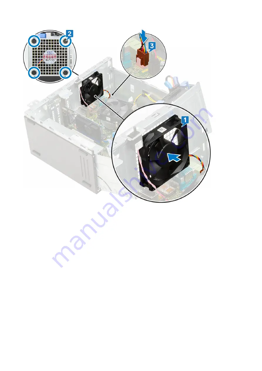
Page 54: ...fter working inside your computer System fan Removing system fan 1 Follow the procedure in Before working inside your computer 2 Remove the a side cover b front bezel c intrusion switch 3 Open the front panel door 4 To remove the system fan a NOTE Ensure to remove the intrusion switch before uninstalling the system fan 54 Disassembly and reassembly ...

Page 55: ...r 3 Installing system fan 1 Align the grooves of the system fan with the grommets on the chassis wall 1 2 Pass the grommets through the corresponding grooves on the system fan 3 Stretch the grommets and slide the system fan toward the computer until it locks into place 2 NOTE Install the lower two grommets first 4 Connect the system fan cable to the connector on the system board 3 Disassembly and ...

Page 56: ...r Optional VGA module Removing optional VGA module 1 Follow the procedure in Before working inside your computer 2 Remove the a Side cover b Front bezel 3 Open the front panel door 4 Remove the system fan 5 To remove the optional VGA module a Remove the two M3X3 screws that secure the optional VGA module to the system 56 Disassembly and reassembly ...

Page 57: ...from the system 2 Installing optional VGA module 1 Insert the VGA module into its slot from the inside of your computer 1 and connect the VGA cable to the connector on the system board 2 2 Replace the two M3X3 screws to secure the optional VGA module to the system Disassembly and reassembly 57 ...

Page 58: ...fore working inside your computer 2 Remove the a side cover b front bezel 3 Open the front panel door 4 Remove the a heat sink fan b heat sink c processor d expansion card e M 2 PCle SSD f SD card reader g memory module 5 Disconnect the following cables from the system board a PSU 1 b power cable and SATA cable 2 c speaker 3 d PSU 4 e power distribution for optical drive and hard drive 5 58 Disass...

Page 59: ...6 To remove the system board a Remove the screws 8 that secure the system board to the computer chassis Disassembly and reassembly 59 ...

Page 60: ...b Slide and lift the system board away from the computer 1 2 60 Disassembly and reassembly ...

Page 61: ... 2 2 Lower the system board into the computer until the connectors at the back of the system board align with the slots on the chassis and the screw holes on the system board align with the standoffs on the computer 3 Tighten the screws 8 to secure the system board to the computer 1 Disassembly and reassembly 61 ...

Page 62: ...e following cables to the system board 5 Route all the cables through the routing clips a power distribution for optical drive and hard drives 1 b PSU 2 c speaker cable 3 d SATA data cable for optical dive and hard drive cables 4 cables 4 e PSU cable 5 62 Disassembly and reassembly ...

Page 63: ...e SSD c expansion card d SD card reader e processor f heat sink g heat sink fan 7 Close the front panel door 8 Install the a front bezel b side cover 9 Follow the procedure in After working inside your computer Disassembly and reassembly 63 ...

Page 64: ...rivers and downloads When troubleshooting downloading or installing drivers it is recommended that you read the Dell Knowledge Based article Drivers and Downloads FAQ 000123347 3 64 Drivers and downloads ...

Page 65: ...ng smart power on Boot Sequence Boot sequence enables you to bypass the System Setup defined boot device order and boot directly to a specific device for example optical drive or hard drive During the Power on Self Test POST when the Dell logo appears you can Access System Setup by pressing F2 key Bring up the one time boot menu by pressing F12 key The one time boot menu displays the devices that ...

Page 66: ...er Optical Drive if available SATA Hard Drive if available Diagnostics NOTE Choosing Diagnostics displays the SupportAssist screen The boot sequence screen also displays the option to access the System Setup screen System Setup options NOTE Depending on the computer and its installed devices the items listed in this section may or may not appear Table 1 General Option Description System Informatio...

Page 67: ...its installed devices the items listed in this section may or may not appear SATA Operation Allows you to configure the operating mode of the integrated hard drive controller Disabled The SATA controllers are hidden RAID ON SATA is configured to support RAID mode selected by default AHCI SATA is configured for AHCI mode Serial Port Allows you to determine how the built in serial port to operate Th...

Page 68: ...ult Intel HD Graphics NOTE If you do not select Auto the on board graphics device will be present and enabled Table 4 Security Option Description Admin Password Allows you to set change and delete the admin password System Password Allows you to set change and delete the system password Internal HDD 0 Password Allows you to set change and delete the computer s internal HDD Internal HDD 3 Password ...

Page 69: ...default Key Storage Enable default SHA 256 default Disabled Enabled default Computrace This field lets you Activate or Disable the BIOS module interface of the optional Computrace Service from Absolute Software Enables or disables the optional Computrace service designed for asset management Deactivate This option is selected by default Disable Activate Chassis Intrusion Allows you to control the ...

Page 70: ...cted file Append from File Adds a key to the current database from a user selected file Delete Deletes the selected key Reset All Keys Resets to default setting Delete All Keys Deletes all the keys NOTE If you disable the Custom Mode all the changes made will be erased and the keys will restore to default settings Table 6 Intel Software Guard Extensions Option Description Intel SGX Enable Allows y...

Page 71: ...lds NOTE This feature does not work if you turn off your computer using the switch on a power strip or surge protector or if Auto Power is set to disabled Deep Sleep Control Allows you to define the controls when Deep Sleep is enabled Disabled Enabled in S5 only Enabled in S4 and S5 This option is Enabled in S4 and S5 by default Fan Control Override Allows you to determine the speed of the system ...

Page 72: ...imal The system boots quickly unless the BIOS has been updated memory changed or the previous POST did not complete Thorough The system does not skip any steps in the boot process Auto This allows the operating system to control this setting this works only when the operating system supports Simple Boot Flag This option is set to Minimal by default Table 10 Manageability Option Description USB pro...

Page 73: ...Table 14 Advanced configurations Option Description ASPM Allows you to activate the state power management Auto Default Disabled L1 Only Updating the BIOS Updating the BIOS in Windows CAUTION If BitLocker is not suspended before updating the BIOS the next time you reboot the system it will not recognize the BitLocker key You will then be prompted to enter the recovery key to progress and the syste...

Page 74: ...s to complete the BIOS update Updating the BIOS from the F12 One Time boot menu Update your computer BIOS using the BIOS update exe file that is copied to a FAT32 USB drive and booting from the F12 One Time boot menu CAUTION If BitLocker is not suspended before updating the BIOS the next time you reboot the system it will not recognize the BitLocker key You will then be prompted to enter the recov...

Page 75: ... access the data stored on your computer if it is not locked and left unattended NOTE System and setup password feature is disabled Assigning a system setup password You can assign a new System or Admin Password only when the status is in Not Set To enter the system setup press F2 immediately after a power on or reboot 1 In the System BIOS or System Setup screen select Security and press Enter The...

Page 76: ...it from System Setup The computer restarts Enabling smart power on To enable Smart Power On and the ability to wake a system from S3 S4 and S5 sleep states with a move of a mouse or press of a key on the keyboard perform these steps 1 Make sure the following BIOS settings under Power Management setup option are set as mentioned here USB Wake Support as Enabled Deep Sleep Control as Disabled 2 Conn...

Page 77: ...tion Always ensure that you are present at the computer terminal when the diagnostic tests are performed Running the ePSA Diagnostics Invoke diagnostics boot by either of the methods that are suggested below 1 Power on the computer 2 As the computer boots press the F12 key when the Dell logo is displayed 3 In the boot menu screen use Up Down arrow key to select the Diagnostics option and then pres...

Page 78: ...supply is normal A device might be malfunctioning or incorrectly installed Refer to the table below for Amber Blinking Pattern diagnostics suggestion and possible failures Steady Off S0 no PWRGD_PS Code fetch 0 Boot Failure This is a system fault error condition including the power supply Only the 5VSB rail on the power supply is working correctly Off Steady S0 no PWRGD_PS Code fetch 1 This indica...

Page 79: ...ected 3 4 BIOS state 7 BIOS Post code Old LED pattern 1001 Fatal Motherboard error 3 5 BIOS state 8 BIOS Post code Old LED pattern 1010 Mem config modules incompatible or invalid config 3 6 BIOS state 9 BIOS Post code Old LED pattern 1011 combine Other pre video activity and resource configuration codes BIOS to eliminate 1100 code 3 7 BIOS state 10 BIOS Post code Old LED pattern 1110 Other pre pos...

Page 80: ...ist OS Recovery User s Guide at www dell com serviceabilitytools Click SupportAssist and then click SupportAssist OS Recovery Battery status lights If the computer is connected to an electrical outlet the battery light operates as follows Alternately blinking amber light and white light An unauthenticated or unsupported non Dell AC adapter is attached to your laptop Re plug battery connector repla...

Page 81: ...r Express Service Code at www dell com support For more information on how to find the Service Tag for your computer see Locate the Service Tag on your computer Dell knowledge base articles for a variety of computer concerns 1 Go to www dell com support 2 On the menu bar at the top of the Support page select Support Knowledge Base 3 In the Search field on the Knowledge Base page type the keyword t...

Reviews: