background image

NOTE:

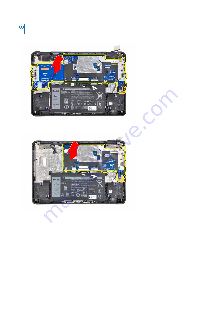
 When removing the system board, carefully lift the system board from the left side to remove it from the

palm-rest assembly. Lifting the system board from another side may damage components connected to the palm-rest.

Chromebook 3110 With a USB-A Port on the Right Side:

Chromebook 3110 Without a USB-A Port on the Right Side:

Installing the system board

Prerequisites

If you are replacing a component, remove the existing component before performing the installation procedure.

About this task

The following image indicates the connectors on your system board.

Removing and installing components

35

Summary of Contents for Chromebook 3110

Page 1: ...Chromebook 3110 Service Manual Regulatory Model P29T Regulatory Type P29T002 P29T003 June 2022 Rev A01 ...

Page 2: ...damage to hardware or loss of data and tells you how to avoid the problem WARNING A WARNING indicates a potential for property damage personal injury or death 2022 Dell Inc or its subsidiaries All rights reserved Dell Technologies Dell and other trademarks are trademarks of Dell Inc or its subsidiaries Other trademarks may be trademarks of their respective owners ...

Page 3: ...ard 16 Installing the SIM card 17 WWAN card 18 Removing the WWAN card 18 Installing the WWAN card 19 Battery 20 Lithium ion battery precautions 20 Removing the 3 cell battery 20 Installing the 3 cell battery 21 Battery cable 23 Removing the battery cable 23 Installing the battery cable 23 Keyboard 24 Removing the keyboard 24 Installing the keyboard 26 Display assembly 27 Removing the display assem...

Page 4: ...ay cable 60 Display back cover and antenna assembly 61 Removing the display back cover and antenna assembly 61 Installing the display back cover and antenna assembly 62 Palm rest assembly 62 Removing the palm rest assembly 62 Installing the palm rest assembly 63 Chapter 3 Troubleshooting 65 Handling swollen Lithium ion batteries 65 Recovering the operating system 65 WiFi power cycle 66 Drain resid...

Page 5: ...touching anything inside your computer ground yourself by touching an unpainted metal surface such as the metal at the back of the computer While you work periodically touch an unpainted metal surface to dissipate static electricity which could harm internal components CAUTION When you disconnect a cable pull it by its connector or its pull tab not the cable itself Some cables have connectors with...

Page 6: ...n and ensure that you remove all jewelry such as watches bracelets or rings prior to bonding yourself and the equipment Electrostatic discharge ESD protection ESD is a major concern when you handle electronic components especially sensitive components such as expansion cards processors memory DIMMs and system boards Very slight charges can damage circuits in ways that may not be obvious such as in...

Page 7: ...t once per week A wrist strap tester is the best method for doing this test If you do not have your own wrist strap tester check with your regional office to find out if they have one To perform the test plug the wrist strap s bonding wire into the tester while it is strapped to your wrist and push the button to test A green LED is lit if the test is successful a red LED is lit and an alarm sounds...

Page 8: ... loose screws inside your computer may severely damage your computer Steps 1 Replace all screws and ensure that no stray screws remain inside your computer 2 Connect any external devices peripherals or cables you removed before working on your computer 3 Replace any media cards discs or any other parts that you removed before working on your computer 4 Connect your computer and all attached device...

Page 9: ...s is to ensure that the correct number of screws and correct screw type is restored when the component is replaced NOTE Some computers have magnetic surfaces Ensure that the screws are not left attached to such surfaces when replacing a component NOTE Screw color may vary with the configuration ordered Table 1 Screw list Component Screw type Quantity Screw image Base cover Captive screws 9 3 cell ...

Page 10: ...port on the right side M2x4 7 System board for systems without USB Type A port on the right side M2x4 4 Display Bezel M2 5x3 8 4 Display panel M2x3 4 Display hinges M2x3 M2 5x2 5 2 4 Major components of Chromebook 3110 The following image shows the major components of Chromebook 3110 10 Removing and installing components ...

Page 11: ...1 Base cover 2 System board 3 Battery 4 Speakers 5 Computer chassis 6 Display assembly Removing and installing components 11 ...

Page 12: ...ntative for purchase options Base cover Removing the base cover Prerequisites 1 Follow the procedure in Before working inside your computer About this task The following images indicate the location of the base cover and provide a visual representation of the removal procedure NOTE For Chromebook 3110 systems shipped with WWAN the base cover is secured using Torx 5 not Phillips 0 screws 12 Removin...

Page 13: ...astic scribe pry the base cover from the U shaped indents at the top and continue working on the sides to open the base cover 3 Lift and remove the base cover off the palm rest assembly 4 Use the pull tab to disconnect the battery cable from the connector system board Removing and installing components 13 ...

Page 14: ...g the installation procedure About this task The following images indicate the location of the base cover and provide a visual representation of the installation procedure NOTE For Chromebook 3110 systems shipped with WWAN the base cover is secured using Torx 5 not Phillips 0 screws 14 Removing and installing components ...

Page 15: ...Removing and installing components 15 ...

Page 16: ...ocedure in After working inside your computer SIM card Removing the SIM card Prerequisites 1 Follow the procedure in Before working inside your computer 2 Remove the base cover About this task NOTE The following steps are applicable only for 4G LTE enabled systems The following image indicates the location of the SIM card and provides a visual representation of the removal procedure Steps 1 Gently...

Page 17: ...tation of the installation procedure Steps 1 Align and slide the SIM card into the SIM card slot on the system board NOTE Align the SIM card parallel to the system board Insert the SIM card carefully in the direction of the SIM card slot 2 Gently push the SIM card until it fits into place For more information about how to enable 4G in your Chromebook see Connect to a mobile data network Next steps...

Page 18: ...mage indicates the location of the WWAN card and provides a visual representation of the removal procedure Steps 1 Remove the screw M2x3 that secures the WWAN card bracket to the WWAN card on the system board 2 Lift and remove the WWAN card bracket from the WWAN card 3 Disconnect the WWAN antenna cables from the connectors on the WWAN card 4 Slide and remove the WWAN card from the WWAN card slot o...

Page 19: ...the notch on the WWAN card with the tab on the WWAN card slot 2 Slide the WWAN card at an angle into the WWAN card slot 3 Connect the WWAN antenna cables to the connectors on the WWAN card 4 Align and place the WWAN card bracket on the system board 5 Replace the screw M2x3 to secure the WWAN card and WWAN card bracket to the system board NOTE For instructions on how to find your computer s Interna...

Page 20: ...not lost or misplaced to prevent accidental puncture or damage to the battery and other system components If the battery gets stuck inside your computer as a result of swelling do not try to release it as puncturing bending or crushing a lithium ion battery can be dangerous In such an instance contact Dell technical support for assistance See www dell com contactdell Always purchase genuine batter...

Page 21: ...y 3 Lift the 3 cell battery off the palm rest assembly Installing the 3 cell battery Prerequisites If you are replacing a component remove the existing component before performing the installation procedure About this task The following images indicate the location of the 3 cell battery and provide a visual representation of the installation procedure Removing and installing components 21 ...

Page 22: ... screws M2x4 to secure the 3 cell battery to the palm rest assembly 3 Route the battery cable through the routing channels between the system board and 3 cell battery Next steps 1 Install the base cover 2 Follow the procedure in After working inside your computer 22 Removing and installing components ...

Page 23: ...ides a visual representation of the removal procedure Steps Disconnect the battery cable from the connector on the battery Installing the battery cable Prerequisites If you are replacing a component remove the existing component before performing the installation procedure About this task The following image indicates the location of the battery cable and provides a visual representation of the in...

Page 24: ...edure in After working inside your computer Keyboard Removing the keyboard Prerequisites 1 Follow the procedure in Before working inside your computer 2 Remove the base cover About this task The following images indicate the location of the keyboard and provide a visual representation of the removal procedure 24 Removing and installing components ...

Page 25: ...Removing and installing components 25 ...

Page 26: ... scribe to carefully pry the keyboard from the latches in the palm rest assembly to release the keyboard from the keyboard bracket in the palm rest assembly 6 Lift and remove the keyboard from the palm rest assembly and carefully pull the keyboard FPC cable through the gap on the palm rest assembly Installing the keyboard Prerequisites If you are replacing a component remove the existing component...

Page 27: ... system board 7 Route the battery cable through the routing channels between the system board and 3 cell battery Next steps 1 Install the base cover 2 Follow the procedure in After working inside your computer Display assembly Removing the display assembly Prerequisites 1 Follow the procedure in Before working inside your computer 2 Remove the base cover 3 Remove the WWAN card for systems enabled ...

Page 28: ...28 Removing and installing components ...

Page 29: ...cket from the display cable connector on the system board 8 Peel the conductive tape that secures the display cable on the display hinges 9 Disconnect and peel back the display cable from the system board 10 Open the display assembly at an angle of 90 degrees and place the system on the edge of a flat surface such that the display assembly extends below the edge of the surface 11 Remove the six sc...

Page 30: ...30 Removing and installing components ...

Page 31: ...ystems enabled with 4G LTE route and adhere the WWAN antenna cables through the routing guides on the palm rest assembly 10 Route the WLAN antenna cables through the routing guides on the palm rest assembly 11 Connect the WLAN antenna cables to the connectors on the WLAN card module NOTE For systems shipped with WLAN capabilities route both WLAN antenna cables underneath the tab on the right displ...

Page 32: ...of the system board While replacing the system board the SIM card must be transferred to the new system board About this task The following images indicate the connectors on your system board 1 WLAN card connector 2 Display cable connector 3 Speaker cable connector 4 Battery cable connector 5 Keyboard cable connector 6 Touchpad cable connector 7 WWAN card connector 8 SIM card connector The followi...

Page 33: ...Removing and installing components 33 ...

Page 34: ...m the connectors on the system board 8 Peel the conductive tape that secures the display cable on the display hinges 9 Peel back the display cable from the system board 10 For systems with USB Type A port on the right side remove the two screws M2x4 that secure the right I O bracket to the palm rest assembly 11 Lift and remove the right I O bracket from the palm rest assembly 12 Remove the screw M...

Page 35: ...ected to the palm rest Chromebook 3110 With a USB A Port on the Right Side Chromebook 3110 Without a USB A Port on the Right Side Installing the system board Prerequisites If you are replacing a component remove the existing component before performing the installation procedure About this task The following image indicates the connectors on your system board Removing and installing components 35 ...

Page 36: ...le connector 7 WWAN card connector 8 SIM card connector The following images indicate the location of the system board and provide a visual representation of the installation procedure NOTE If the CPU thermal pad on the palm rest underneath the system board gets detached adhere it back onto the palm rest 36 Removing and installing components ...

Page 37: ...Removing and installing components 37 ...

Page 38: ...e system board from the left side to remove it from the palm rest assembly Lifting the system board from another side may damage components connected to the palm rest Chromebook 3110 With a USB A Port on the Right Side Chromebook 3110 Without a USB A Port on the Right Side 38 Removing and installing components ...

Page 39: ...nd then adhere the piece of conductive tape to secure the display cable in place 11 Connect the display cable touchpad Flexible Flat Cable FFC keyboard Flexible Printed Circuits cable FPC and speaker cable to the connectors on the system board 12 Align and place the display cable bracket on the display cable connector on the system board 13 Replace the screw M2x4 to secure the display cable bracke...

Page 40: ... 2 Remove the base cover 3 Remove the 3 cell battery About this task The following image indicates the location of the speakers and provides a visual representation of the removal procedure Steps 1 Peel back the clear tape that secures the speaker cable to the palm rest 40 Removing and installing components ...

Page 41: ...palm rest the speaker cables must be routed through the routing channels in the palm rest and underneath the tape with an arrow to avoid damaging the speaker cables when installing the base cover 5 Lift the speakers along with their cables off the palm rest assembly Installing the speakers Prerequisites If you are replacing a component remove the existing component before performing the installati...

Page 42: ...peaker cable through the routing channels in the palm res assembly NOTE The speaker cables must be routed through the routing channels at the bottom of the palm rest and underneath the tape with an arrow to avoid damaging the speaker cables when installing the base cover 42 Removing and installing components ...

Page 43: ...er 3 Follow the procedure in After working inside your computer Display bezel Removing the display bezel Prerequisites 1 Follow the procedure in Before working inside your computer 2 Remove the base cover 3 Remove the WWAN card for systems enabled with 4G LTE 4 Remove the display assembly About this task The following images indicate the location of the display bezel and provide a visual represent...

Page 44: ...44 Removing and installing components ...

Page 45: ...e the new stickers over the screws once the screws have been secured NOTE A blade or a plastic scribe can be used to peel the display bezel stickers 2 Remove the four screws M2 5x3 8 that secure the display bezel to the display assembly 3 Use a plastic scribe to carefully pry open the two recesses along the bottom side of the display bezel near the hinge caps Removing and installing components 45 ...

Page 46: ... pry the display bezel as peeling the adhesive on display bezel may damage the display panel 5 Use a plastic scribe to pry open both hinge caps of the display bezel 6 Use a plastic scribe to pry open the outside edge of the left right and top sides of the display bezel 46 Removing and installing components ...

Page 47: ...7 Carefully peel off and remove the display bezel from the display assembly Removing and installing components 47 ...

Page 48: ...component remove the existing component before performing the installation procedure About this task The following images indicate the location of the display bezel and provide a visual representation of the installation procedure 48 Removing and installing components ...

Page 49: ...Removing and installing components 49 ...

Page 50: ...e display bezel NOTE A new set of stickers is included with replacement display bezel When replacing the new display bezel adhere the new stickers over the screws once the screws have been secured Next steps 1 Install the display assembly 2 Install the WWAN card for systems enabled with 4G LTE 3 Install the base cover 4 Follow the procedure in After working inside your computer Display panel Remov...

Page 51: ...lay assembly 5 Remove the display bezel About this task The following images indicate the location of the display panel and provide a visual representation of the removal procedure Removing and installing components 51 ...

Page 52: ...ber spacer on the display cable 6 Disconnect the display cable from the connector on the back of the display panel 7 Lift and remove the display panel from the display assembly Installing the display panel Prerequisites If you are replacing a component remove the existing component before performing the installation procedure About this task The following images indicate the location of the displa...

Page 53: ...Removing and installing components 53 ...

Page 54: ...ere the piece of conductive tape to secure the display cable in place 4 Adhere the conductive tape to secure the display cable connector 5 Flip the display panel to align it with the screw holders on the display assembly 6 Replace the four screws M2x3 to secure the display panel to the display assembly Next steps 1 Install the display bezel 2 Install the display assembly 3 Install the WWAN card fo...

Page 55: ...amera cable from connector on the camera module 2 Peel back the foil tape that secures the camera module 3 Use a plastic scribe to carefully pry up the camera from the bottom side starting from the locations marked by the arrows 4 Lift and remove the camera module from the display assembly Installing the front facing camera Prerequisites If you are replacing a component remove the existing compone...

Page 56: ...abled with 4G LTE 4 Install the base cover 5 Follow the procedure in After working inside your computer Display hinges Removing the display hinges Prerequisites 1 Follow the procedure in Before working inside your computer 2 Remove the base cover 3 Remove the WWAN card for systems enabled with 4G LTE 4 Remove the display assembly 5 Remove the display bezel 6 Remove the display panel About this tas...

Page 57: ...re the display hinges to the display back cover 4 Lift and remove the display hinges from the display back cover Installing the display hinges Prerequisites If you are replacing a component remove the existing component before performing the installation procedure About this task The following image indicates the location of the display hinges and provides a visual representation of the installati...

Page 58: ... secure the display cable in place NOTE For Chromebook 3110 systems shipped with WWAN route the display cable along the routing channels at the bottom left side of the display back cover and then adhere the piece of conductive tape to secure the display cable in place Next steps 1 Install the display panel 2 Install the display bezel 3 Install the display assembly 4 Install the WWAN card for syste...

Page 59: ...icates the location of the display cable and provides a visual representation of the removal procedure Steps 1 Peel back the conductive tape from the left display hinge that secures the display cable in place 2 Disconnect the display cable from the connector on the camera module 3 Peel back the conductive tape that secures the display cable in place 4 Unroute the display cable from the routing cha...

Page 60: ...ing channel on the display back cover 3 Adhere the conductive tape to secure the display cable in place 4 Connect the display cable to the connector on the camera module 5 Adhere the conductive tape on the left display hinge to secure the display cable in place NOTE For Chromebook 3110 systems shipped with WWAN route the display cable along the routing channels at the bottom left side of the displ...

Page 61: ...l 7 Remove the camera 8 Remove the display hinges 9 Remove the display cable About this task NOTE The display back cover and antenna assembly cannot be further disassembled once all the pre removal parts procedures are completed If the WLAN and or WWAN antenna cables are malfunctioning and are required to be replaced replace the entire display back cover and antenna assembly The image below shows ...

Page 62: ...ostrequisites to install the display back cover and antenna assembly Next steps 1 Install the display cable 2 Install the display hinges 3 Install the camera 4 Install the display panel 5 Install the display bezel 6 Install the display assembly 7 Install the WWAN card for systems enabled with 4G LTE 8 Install the base cover 9 Follow the procedure in After working inside your computer Palm rest ass...

Page 63: ... be replaced replace the entire palm rest assembly The following image shows the palm rest assembly after performing the pre removal parts procedures for any palm rest assembly replacement Steps After performing the pre requisites you are left with the palm rest assembly Installing the palm rest assembly Prerequisites If you are replacing a component remove the existing component before performing...

Page 64: ...xt steps 1 Install the speakers 2 Install the system board 3 Install the display assembly 4 Install the keyboard 5 Install the 3 cell battery 6 Install the WWAN card for systems enabled with 4G LTE 7 Install the base cover 8 Follow the procedure in After working inside your computer 64 Removing and installing components ...

Page 65: ...ry to high temperatures or disassemble battery packs and cells Do not apply pressure to the surface of the battery Do not bend the battery Do not use tools of any type to pry on or against the battery If a battery gets stuck in a device as a result of swelling do not try to free it as puncturing bending or crushing a battery can be dangerous Do not attempt to reassemble a damaged or swollen batter...

Page 66: ... before removing or replacing any components in your computer Draining residual flea power also known as a performing a hard reset is also a common troubleshooting step if your computer does not power on or boot into the operating system To drain residual flea power perform a hard reset Steps 1 Turn off your computer 2 Disconnect the power adapter from your computer 3 Remove the base cover 4 Remov...

Page 67: ...Troubleshooting 67 ...

Page 68: ... dell com support For more information on how to find the Service Tag for your computer see Locate the Service Tag on your computer Dell knowledge base articles for a variety of computer concerns 1 Go to www dell com support 2 On the menu bar at the top of the Support page select Support Knowledge Base 3 In the Search field on the Knowledge Base page type the keyword topic or model number and then...

Reviews: