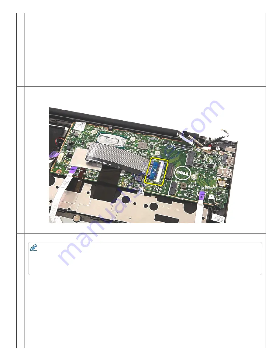
4. Disconnect the keyboard cable, and gently peel it off the system board.
5. Remove two screws securing the system board in place.
NOTE:
Dell Chromebook 13 has a unique hardware writeprotect screw. The hardware writeprotect screw needs to be reinserted back to its original designated
location on the system board (topright screw).
The hardware writeprotect screw needs to be removed in order for the RMA Shim to successfully write VPD (Vendor Product Data, e.g. Serial Number,
Keyboard Part Code, Service Tag, Asset Tag, Model Name, Region), else Shop Floor Tests would fail. If the hardware writeprotect screw was previously
removed for Shop Floor Tests, please reinsert the screw back into place before running Google Required Tests.
Summary of Contents for Chromebook 13-7310
Page 10: ...Bottom Cover ...
Page 16: ...5 Remove the battery from the system 6 Disconnect the battery cable from the battery ...
Page 17: ...7 Complete ...
Page 20: ...4 Remove the M 2 SSD from the system board 5 Complete ...
Page 23: ...3 Remove the single screw securing the WLAN bracket 4 Remove the WLAN bracket from the system ...
Page 24: ...5 Disconnect any antennas that may be connected to the WLAN card ...
Page 25: ...6 Remove the WLAN card from the system board 7 Complete ...
Page 29: ...5 Lift up and remove the I O board 6 Disconnect the I O board cable from the I O board ...
Page 32: ...2 Establishing image 3 Disconnect the fan cable from the system board ...
Page 33: ...4 Remove the two screws securing the fan in place 5 Lift up and remove the fan ...
Page 34: ...6 Complete ...
Page 37: ...4 Lift up and remove the heat sink 5 Complete ...
Page 41: ...5 Lift up and remove the DC in jack from the system 6 Complete ...
Page 49: ...6 Lift up and remove the system board 7 Complete ...
Page 55: ...2 Establishing image 3 Release the antennas from the routing channel ...
Page 56: ...4 Remove the four screws securing the LCD assembly to the system 5 Gently open the palmrest ...
Page 57: ...6 Separate the palmrest from the LCD assembly 7 Complete ...
Page 60: ...3 Use a plastic scribe to gently pry the hinge cover off the LCD assembly 4 Complete ...
Page 67: ...5 Complete ...
Page 70: ...4 Remove the left LCD hinge 5 Release the antenna cables from the right LCD hinge hook ...
Page 74: ...2 Establishing image 3 Remove the four screws securing the LCD panel to the LCD assembly ...
Page 75: ...4 Carefully flip over the LCD panel 5 Peel off the adhesive tape securing the eDP cable ...
Page 76: ...6 Unlock the metal clip securing the eDP connector 7 Disconnect the eDP cable ...
Page 77: ...8 Remove the LCD panel from the LCD assembly ...
Page 78: ...9 Complete ...
Page 81: ...4 Peel open the cloth tape 5 Release the eDP cable from the routing channel ...
Page 82: ...6 Disconnect the camera cable 7 Remove the eDP cable from the LCD cover ...
Page 83: ...8 Complete ...
Page 86: ......


