050
050
/
CHAPTER 9: FANS
Replacing the PCI Fan
Follow the instructions in “Before You Begin” on page
1.
6.
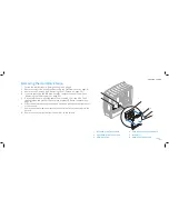
Orient the PCI-fan cable downward and replace the PCI fan in the PCI-fan
2.
shroud.
Align the rubber grommets with the openings in each corner of the PCI-fan
3.
shroud, and then pull the grommets through until they snap into place.
Slide the PCI-fan shroud into the chassis.
4.
Replace the two screws that secure the PCI-fan shroud to the chassis.
5.
Connect the PCI-fan cable to the PCI_FAN1 connector on the master I/O
6.
board (see “Master I/O Board Connectors” on page 12).
Replace the drive-bay shroud (see “Replacing the Drive-Bay Shroud” on
7.
page 23).
Replace the left side-panel (see “Replacing the Left Side-Panel” on page
8.
15).
Connect your computer and devices to electrical outlets, and then turn
9.
them on.
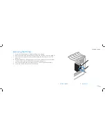
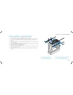
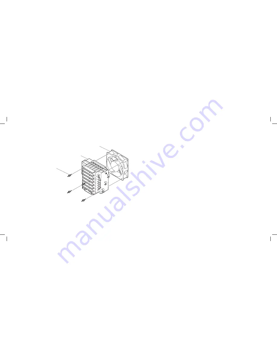
Pull to detach the four rubber grommets that secure the PCI fan to the
7.
PCI-fan shroud.
3
2
1
1 rubber grommets (4)
3 PCI fan
2 PCI-fan shroud
Summary of Contents for Alienware Area-51 ALX
Page 1: ...01 01 ALIENWARE AREA 51 SERVICE MANUAL ...
Page 9: ...CHAPTER 2 TECHNICAL OVERVIEW 09 09 CHAPTER 2 TECHNICAL OVERVIEW CHAPTER 2 TECHNICAL OVERVIEW ...
Page 13: ...CHAPTER 3 CHASSIS 013 013 CHAPTER 3 CHASSIS CHAPTER 3 CHASSIS ...
Page 20: ...CHAPTER 4 SHROUDS 020 020 CHAPTER 4 SHROUDS CHAPTER 4 SHROUDS ...
Page 33: ...CHAPTER 7 DRIVES 033 033 CHAPTER 7 DRIVES CHAPTER 7 DRIVES ...
Page 44: ...CHAPTER 8 FRONT BEZEL 044 044 CHAPTER 8 FRONT BEZEL CHAPTER 8 FRONT BEZEL ...
Page 47: ...CHAPTER 9 FANS 047 047 CHAPTER 9 FANS CHAPTER 9 FANS ...
Page 57: ...CHAPTER 11 TOP I O PANEL 057 057 CHAPTER 11 TOP I O PANEL CHAPTER 11 TOP I O PANEL ...
Page 62: ...CHAPTER 12 BLUETOOTH MODULE 062 062 CHAPTER 12 BLUETOOTH MODULE CHAPTER 12 BLUETOOTH MODULE ...
Page 70: ...CHAPTER 14 PROCESSOR 070 070 CHAPTER 14 PROCESSOR CHAPTER 14 PROCESSOR ...
Page 75: ...CHAPTER 15 MASTER I O BOARD 075 075 CHAPTER 15 MASTER I O BOARD CHAPTER 15 MASTER I O BOARD ...
Page 79: ...CHAPTER 16 SYSTEM BOARD 079 079 CHAPTER 16 SYSTEM BOARD CHAPTER 16 SYSTEM BOARD ...
Page 83: ...CHAPTER 17 POWER SUPPLY 083 083 CHAPTER 17 POWER SUPPLY CHAPTER 17 POWER SUPPLY ...
Page 87: ...CHAPTER 18 BATTERY 087 087 CHAPTER 18 BATTERY CHAPTER 18 BATTERY ...
Page 93: ...CHAPTER 19 SYSTEM SETUP 093 093 CHAPTER 19 SYSTEM SETUP CHAPTER 19 SYSTEM SETUP ...


