019
019
/
CHAPTER 3: CHASSIS
1
1
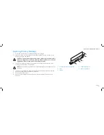
chassis-intrusion switch
Removing the Chassis-Intrusion Switch
Follow the instructions in “Before You Begin” on page
1.
6.
Remove the left side-panel (see “Removing the Left Side-Panel” on page
2.
15).
Disconnect the chassis-intrusion switch cable from the master I/O board
3.
connector.
Slide the chassis-intrusion switch towards the top of the computer and then
4.
pull it away.
Replacing the Chassis-Intrusion Switch
Follow the instructions in “Before You Begin” on page
1.
6.
Route the chassis-intrusion switch cable through the chassis and connect it
2.
to the master I/O board connector.
Replace the chassis-intrusion switch in the chassis.
3.
Slide the chassis-intrusion switch towards the bottom of the computer until
4.
the chassis-intrusion switch snaps into place.
Replace the left side-panel (see “Replacing the Left Side-Panel” on page
5.
15).
Connect your computer and devices to electrical outlets, and then turn
6.
them on.
Summary of Contents for Alienware Area-51 ALX
Page 1: ...01 01 ALIENWARE AREA 51 SERVICE MANUAL ...
Page 9: ...CHAPTER 2 TECHNICAL OVERVIEW 09 09 CHAPTER 2 TECHNICAL OVERVIEW CHAPTER 2 TECHNICAL OVERVIEW ...
Page 13: ...CHAPTER 3 CHASSIS 013 013 CHAPTER 3 CHASSIS CHAPTER 3 CHASSIS ...
Page 20: ...CHAPTER 4 SHROUDS 020 020 CHAPTER 4 SHROUDS CHAPTER 4 SHROUDS ...
Page 33: ...CHAPTER 7 DRIVES 033 033 CHAPTER 7 DRIVES CHAPTER 7 DRIVES ...
Page 44: ...CHAPTER 8 FRONT BEZEL 044 044 CHAPTER 8 FRONT BEZEL CHAPTER 8 FRONT BEZEL ...
Page 47: ...CHAPTER 9 FANS 047 047 CHAPTER 9 FANS CHAPTER 9 FANS ...
Page 57: ...CHAPTER 11 TOP I O PANEL 057 057 CHAPTER 11 TOP I O PANEL CHAPTER 11 TOP I O PANEL ...
Page 62: ...CHAPTER 12 BLUETOOTH MODULE 062 062 CHAPTER 12 BLUETOOTH MODULE CHAPTER 12 BLUETOOTH MODULE ...
Page 70: ...CHAPTER 14 PROCESSOR 070 070 CHAPTER 14 PROCESSOR CHAPTER 14 PROCESSOR ...
Page 75: ...CHAPTER 15 MASTER I O BOARD 075 075 CHAPTER 15 MASTER I O BOARD CHAPTER 15 MASTER I O BOARD ...
Page 79: ...CHAPTER 16 SYSTEM BOARD 079 079 CHAPTER 16 SYSTEM BOARD CHAPTER 16 SYSTEM BOARD ...
Page 83: ...CHAPTER 17 POWER SUPPLY 083 083 CHAPTER 17 POWER SUPPLY CHAPTER 17 POWER SUPPLY ...
Page 87: ...CHAPTER 18 BATTERY 087 087 CHAPTER 18 BATTERY CHAPTER 18 BATTERY ...
Page 93: ...CHAPTER 19 SYSTEM SETUP 093 093 CHAPTER 19 SYSTEM SETUP CHAPTER 19 SYSTEM SETUP ...


