background image

1 – 84

Chapter 1  Troubleshooting

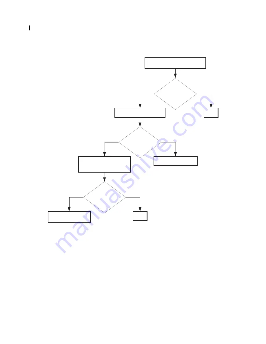
FIP-48  Imaging Drum 091-912/CRUM ID 093-965

Replace the PHD ASSY.

No

Yes

Possible causative parts:PHD ASSY (PL6.1.1)
                                        PWBA MCU (PL9.1.16)

Checking the PHD ASSY installation
Reseat the PHD ASSY.

Does the error still

occur when turning

on the power?

Checking the PHD ASSY type

Is the PHD ASSY

installed the 5110CN?

No

Yes

Does the error still

occur when turning

on the power?

No

Yes

END

Checking after replacing the 
PHD ASSY
Replace the PHD ASSY.

END

Replace the PWBA 
MCU. (RRP9.7)

Summary of Contents for 5110cn - Color Laser Printer

Page 1: ...Dell 5110cn Service Manual 12 Nov 2007 ...

Page 2: ...ten permission of Dell Inc is strictly forbidden Trademarks used in this text Dell and the DELL logo are trademarks of Dell Inc Other trademarks and trade names may be used in this document to refer to the entities claiming the marks and names of their products Dell Inc disclaims any proprietary interest in trademarks and trade names other than its own ...

Page 3: ...l This document is protected by copyright Do not photocopy or duplicate any part of this document in any form without written permission from Dell Inc Dell Inc will not assume responsibility for accidental or incidental damages resulting from technical or editorial errors or omissions in this manual the issue of this manual the execution of descriptions ...

Page 4: ...dental information to descriptions 3 Related documents T Instruction manuals standard manuals Describe operation and handling of this laser printer T Performance specifications Describe in detail various specifications of this laser printer In the event of discrepancy between this manual and the performance specifications the performance specifications shall take preference T Video interface speci...

Page 5: ...ep the power supply off during maintenance operation to prevent electric shock burns and other damages Keep the power plug disconnected during the maintenance operation If the power supply should be kept connected for measurement of voltage or other similar reasons sufficient care should be given to prevent electric shock by following the procedures of this manual While the printer is ON never tou...

Page 6: ...ing units while the printer is running 4 3 High temperature units When servicing high temperature units securing unit etc be sure to turn them OFF to prevent burns injuries and other troubles remove the power plug and start service processes after they have cooled down enough Immediately after completion of operation they are still hot Start services after more than 40 minutes ...

Page 7: ...le of having an injurious action on the human body not to extend the danger over the workers as well as other people around the printer Laser beams have features as follows Frequencies are smaller in width than other beams sun and electric bulbs and phases are uniform so that high monochromatic and convergence performance can be obtained and thin beams of light can reach places at a long distance ...

Page 8: ...ion labels are attached to this laser printer to prevent accidents Check those labels for their peeling or stain when servicing the printer 4 5 1 Caution label for high temperature units 4 5 2 Caution label regarding toner cartridge Ida_Sec00_010FA Ten00004KA ...

Page 9: ...Intro 7 4 5 3 Caution label regarding Imaging Drum and Transfer Roller Ida_Sec00_005FA Ida_Sec00_009FA ...

Page 10: ...Intro 8 4 5 4 Caution label regarding MPF and paper tray 4 5 5 Caution label regarding Developer Frame Ida_Sec00_006FA Ida_Sec00_007FA ...

Page 11: ...Intro 9 4 5 6 Caution label regarding Print Head Ida_Sec00_008FA ...

Page 12: ... Printer The printer must be carried horizontally with two or more persons Extreme care must be taken to avoid personal injuries Check the printer visually for evidence of any damage Peel all tapes off the printer Ten00011KA ...

Page 13: ...ntro 6 4 5 3 Caution label regarding PHD ASSY and BTR ASSY Intro 7 4 5 4 Caution label regarding MSI and paper tray Intro 8 4 5 5 Caution label regarding FRAME ASSY DEVE Intro 8 4 5 6 Caution label regarding ROS ASSY Intro 9 Unpacking the Printer Intro 10 Chapter 1 Troubleshooting 1 1 Chapter 2 Operation of Diagnostic 2 1 Chapter 3 Removal and Replacement Procedures 3 1 Chapter 4 Plug Jack P J Con...

Page 14: ...384 Restart Printer 1 35 FIP 9 007 342 007 345 007 346 007 348 Restart Printer 1 36 FIP 10 007 343 007 345 007 347 007 348 Restart Printer 1 37 FIP 11 007 344 007 346 007 347 007 348 Restart Printer 1 38 FIP 12 009 340 009 341 Restart Printer 1 39 FIP 13 009 360 009 361 009 362 009 363 Restart Printer 1 40 FIP 14 010 354 Restart Printer 1 41 FIP 15 010 378 010 379 010 380 010 381 010 382 010 383 0...

Page 15: ... 972 1 81 FIP 46 Imaging Drum 091 935 1 82 FIP 47 Ready to Print 094 402 1 83 FIP 48 Imaging Drum 091 912 CRUM ID 093 965 1 84 FIP 49 Replace Fuser 010 351 1 85 FIP 50 Insert Fuser 010 317 1 86 FIP 51 Ready to Print 010 421 1 87 FIP 52 Fuser Type 010 358 CRUM ID 093 964 1 88 FIP 53 Transfer Roller 094 911 1 89 FIP 54 Ready to Print 094 422 1 90 FIP 55 BTR Not Detected 094 910 1 91 FIP 56 Load Tray...

Page 16: ...0 Unfused Image or Image Easily Rubs off of Page 1 139 P11 Vertical Dark Line 1 140 P12 Afterimage Ghost 1 141 P13 Partial Deletion 1 142 P14 Horizontal Line Periodical 1 143 P15 Fade Horizontal Vertical 1 145 P16 Color Registration Color Shift 1 147 3 6 Other FIP 1 150 FIP No Power 1 150 FIP Multiple Feed 1 151 4 Abnormal Noise Trouble 1 152 4 1 Entry Chart for Abnormal Noise Troubleshooting 1 15...

Page 17: ...Chapter 1 Troubleshooting Chapter 1 Troubleshooting CONTENTS ...

Page 18: ...tion of a trouble proceed with the troubleshooting process efficiently making use of the Fault Isolation Procedure FIP Operation of Diag tools Chapter 2 Wire connecting diagram Chapter 7 and Principle of operation Chapter 6 1 1 Flow of Troubleshooting Flow of the troubleshooting is as follows Installation status check Trouble status check Execute FIP Trouble recovery check End Send back printer or...

Page 19: ...ot installed close to water service humidifier heat generating unit or fire in very dusty place or a place exposed to air flow from the air conditioning system 6 The laser printer is not installed in a place where volatile gas or inflammable gas is generated 7 The laser printer is not installed under direct sunbeams 8 The laser printer is installed in a well ventilated place 9 The laser printer is...

Page 20: ...quired When checking some parts with the left cover removed and power ON high voltage may be applied by the HVPS Be sure to remove the connector P J141 on the HVPS When connecting the connector P J141 on the HVPS according to the instructions of the FIP never touch the HVPS and parts of high voltage 4 When using Diag tools or other tools of high voltage be sure to keep them covered except when oth...

Page 21: ...connected P12 Plug side with the connector P J12 removed except when attached directly to the board J12 Jack side with the connector P J12 removed except when attached directly to the board 7 P J1 2PIN P J3 4PIN in the FIP means measurement with the plus side of the measuring instrument connected to P J1 and the minus side to 4PIN of P J3 8 P J P 12 in the FIP means measurement for all terminals c...

Page 22: ...f the paper tray at the lower part of the printer is referred to as try 1 the first level of the paper pick up unit feeder unit as try 2 and the second level as the tray3 16 In the FIP existence and non existence of Diag tools maintenance tools are distinguished in some cases Correct troubles according to the instructions in the FIP 17 In the FIP procedures are differentiated depending on specific...

Page 23: ...meet the specifications Reinstall the print media fall within the print media guidelines Yes If not Verify that the settings of the printer for the type and size of the print media are correct Reset the printer settings Yes Reinstall the Fuser Assy BTR Assy PHD Assy and four TONER Cartridges to the printer If not Inspect there is no damage on the tabs for safety interlock of the Covers and Doors R...

Page 24: ... status code or LCD display is displayed When image quality trouble is occurred When abnormal noise is occurred Instruct how to operate End of work Refer to 3 2 Status Code List Refer to 3 3 LCD Display Refer to 3 4 Error Code FIP Refer to 3 5 Entry Chart for Image Quality Troubleshooting Refer to 3 5 Image Quality FIP Refer to 4 1 Entry Chart for Abnormal Noise Troubleshooting Refer to 4 2 Operat...

Page 25: ... 2 FIP The Level 2 FIP is the trouble diagnostic procedure to sort various troubles in addition to the error codes In the troubleshooting executing the steps given in the FIP or checking procedure allows you to find out a cause of trouble in a short time ...

Page 26: ...receiving error signals from the Rear and Front Fans FIP 1 FIP 2 001 364 Restart Printer Contact Support IfMessageReturns IOT Fan Motor 5 Failure MCU detects an error upon receiving error signals from the Rear and LV Fans FIP 1 FIP 3 001 365 Restart Printer Contact Support IfMessageReturns IOT Fan Motor 6 Failure MCU detects an error upon receiving error signals from the Front and LV Fans FIP 2 FI...

Page 27: ...inter Contact Support IfMessageReturns IOT Motor Failure Deve Motor fail is detected MCU detects an error upon receiving error signal from the Motor FIP 10 007 344 Restart Printer Contact Support IfMessageReturns IOT Motor Failure Fuser Motor fail is detected MCU detects an error upon receiving error signal from the Motor FIP 11 007 345 Restart Printer Contact Support IfMessageReturns IOT Motor Fa...

Page 28: ...2 Restart Printer Reseat C Toner Contact Support IOT C Toner CRUM Error Cyan Toner CRUM Communication Error is detected Printer can not read the CRUM data of the cyan toner cartridge FIP 13 009 363 Restart Printer Reseat K Toner Contact Support IOT K Toner CRUM Error Black Toner CRUM Communication Error is detected Printer can not read the CRUM data of the black toner cartridge FIP 13 010 354 Rest...

Page 29: ...5 Restart Printer Contact Support IfMessageReturns ESS On Board RAM W R Check Error The error is detected by On board RAM W R check during initialization FIP 16 016 316 Restart Printer Reseat Memory Contact Support ESS DIMM Slot RAM W R Check Error The error is detected by DIMM slot RAM W R check during initialization FIP 18 016 317 Restart Printer Contact Support IfMessageReturns ESS ROM Check Ma...

Page 30: ...h ROM FIP 19 016 332 Restart Printer Reseat MPC Contact Support MPC RAM R W Test Error The error is detected by MPC RAM W R check FIP 19 016 333 Restart Printer Reseat MPC Contact Support MPC Flash ROM Application Module Checksum Error Checksum error in the MPC Flash ROM FIP 19 016 334 Restart Printer Reseat MPC Contact Support MPC MAC Address Checksum Error Checksum error in the MPC MAC address F...

Page 31: ...ernet parity RAM R W check FIP 16 016 346 Restart Printer Contact Support IfMessageReturns ESS Network Internal Loopback Error The error is detected by On Board Network Internal Loopback check FIP 16 016 350 Restart Printer Reseat Parallel Contact Support IEEE1284 Data Error The error is detected by IEEE1284 controller FIP 21 016 360 Restart Printer Reseat MPC Contact Support PCI Option 0 MPC I F ...

Page 32: ...per IOT Registration Jam 1 The regi sensor cannot detect passage of paper within specified time 2 The regi sensor detected a paper while power is on or interlock is closed FIP 25 Paper Jam 071 101 Open Tray Remove Paper Open close Front Latch IOT Feed Jam The regi sensor cannot detect paper within specified time FIP 26 Paper Jam 077 907 Push Side Button Remove Paper IOT Duplex Jam 1 The duplex jam...

Page 33: ...pe Specified Tray Empty When a tray is specified the tray is empty No Suitable Paper 1 When the printer is waiting for a job or APS is specified all the trays including MPF installed on the printer are empty All Tray Empty 2 When APS is specified a size of paper in all trays including MPF is mismatched All Tray Size Mismatch 3 When a tray is specified a size of paper in the specified tray includin...

Page 34: ...ER can not detect the toner cartridge FIP 32 Y FIP 33 M FIP 34 C FIP 35 K Replace Toner 093 930 093 931 093 932 093 933 Replace XXX Toner NOTE XXX Toner color 093 930 Yellow 093 931 Magenta 093 932 Cyan 093 933 Black IOT Toner Empty The toner empty is detected The value of the Toner Cartridge counter has reached the replacement time The No Toner Sensor on the DISPENSER ASSY HI detected the no tone...

Page 35: ...Y Insert Drum 091 972 Insert Reseat Imaging Drum IOT PHD Detached The PHD detached is detected FIP 45 Imaging Drum 091 935 Replace Imaging Drum IOT PHD Life Over The PHD life over is detected FIP 46 Ready to Print 094 402 Imaging Drum Replace Soon PHD Life Warning The PHD life warning is detected The value of the PHD counter has reached the replacement time FIP 47 Imaging Drum 091 912 Reseat Imagi...

Page 36: ...of the other company FIP 52 CRUM ID 093 964 Reseat Fuser IOT CRUM ID Error The fuser CRUM ID error is detected The Fuser CRUM ID read by the MCU is different from the one that was recorded FIP 52 BTR Transfer Roller 094 911 Replace Transfer Roller IOT BTR Life Over The BTR life over is detected The value of the BTR counter has reached the replacement time FIP 53 Ready to Print 094 422 Replace Tran...

Page 37: ...ected the no tray FIP 56 Tray Detached 024 945 Push in Tray Tray Detached When the printer is waiting for a job or APS is specified all the trays are detached All Tray Detached The Tray Size Switch detected the no tray Tray Detached 024 946 024 947 024 948 024 949 Push in Tray N NOTE N Tray number 024 946 Tray 1 024 947 Tray 2 024 948 Tray 3 024 949 Tray 4 Tray Detached When a tray is specified th...

Page 38: ...ay Empty 2 When APS is specified a size of paper in all trays including MPF is mismatched All Tray Size Mismatch 3 When a tray specified the tray is empty Specified Tray Empty 4 When a tray is specified a size of paper in the specified tray including MPF is mismatched Specified Tray Size Mismatch FIP 30 Load MPF 024 969 Load MPF XXX Load MPF YYY NOTE XXX Paper size YYY Media type Cover Open Close ...

Page 39: ...city The print data size exceeded the memory or the hard disk capacity of the printer FIP 60 PCL Request 016 720 Data Violation Press Set PDL Error PCL error occurs The print data cannot be processed by PCL FIP 61 Invalid Job 016 799 Data Violation Press Set Job Environment Violation Detects violation data for the print condition The print data specifies paper type size not available for the print...

Page 40: ...ion error occurred between MPC and ESS during download FIP 65 Erase Flash Err 016 392 Contact Support IfMessageReturns Download Error An error occurred erasing the Flash FIP 16 Write Flash Err 016 393 Contact Support IfMessageReturns Download Error An error occurred writing to the Flash FIP 16 Verify Error 016 394 Contact Support IfMessageReturns Download Error An error occurred verifying the Flas...

Page 41: ... 1 Troubleshooting Other Reached Limits 016 759 Over your limits Press Set Auditron Error The number of registered users exceeded its upper limit FIP 66 Problem Error Message Error Contents FIP to be referred Flip ...

Page 42: ...REAR function normally Checked by Digital Output DO 3f in IOT Diagnosis In the test close the INTERLOCK SWITCH Replace the PWBA MCU RRP9 7 Checking after replacing the FAN REAR Replace the FAN REAR RRP1 6 Does the error still occur when turning on the power No Yes END Checking after replacing the PWBA MCU Replace the PWBA MCU RRP9 7 Does the error still occur when turning on the power No Yes END R...

Page 43: ...ng the FAN FRONT No Yes Does the FAN FRONT function normally Checked by Digital Output DO 45 in IOT Diagnosis In the test close the INTERLOCK SWITCH Reseat the FAN FRONT Replace the PWBA MCU RRP9 7 END No Yes Does the FAN FRONT function normally Checked by Digital Output DO 45 in IOT Diagnosis In the test close the INTERLOCK SWITCH Replace the FAN FRONT ...

Page 44: ...ed by Digital Output DO 42 in IOT Diagnosis In the test close the INTERLOCK SWITCH Checking after replacing the FAN LV Replace the FAN LV RRP1 13 Does the error still occur when turning on the power No Yes END Checking after replacing the PWBA MCU Replace the PWBA MCU RRP9 7 Does the error still occur when turning on the power No Yes END Replace the LVPS RRP9 3 Reseat the FAN LV RRP1 13 Does the e...

Page 45: ...ew PWBA Possible causative parts PWBA MCU PL9 1 16 PWBA HVPS 9 1 21 Yes No Does the error still occur when turning on the power Checking the connector connection Reseat the following connectors P J16 and P J191 on the PWBA MCU P J141 on the PWBA HVPS P J144 on the PWBA EEPROM STD Checking after replacing the PWBA HVPS Replace the PWBA HVPS RRP9 9 END Yes No Does the error still occur when turning ...

Page 46: ...king the FUSER ASSY installation Reseat the FUSER ASSY Checking the PHD ASSY installation Reseat the PHD ASSY and check the CRUM connector Yes No Does the error still occur when turning on the power END END Checking the PWBA MCU installation Reseat the PWBA MCU RRP9 7 Yes No Does the error still occur when turning on the power END Checking the PWBA HVPS installation Reseat the PWBA HVPS RRP9 9 Yes...

Page 47: ...ing the PHD ASSY Replace the PHD ASSY Yes No Does the error still occur when turning on the power END END Checking after replacing the FUSER ASSY Replace the FUSER ASSY Yes No Does the error still occur when turning on the power END Checking after replacing the PWBA HVPS Replace the PWBA HVPS RRP9 9 Yes No Does the error still occur when turning on the power END Replace the PWBA MCU RRP97 ...

Page 48: ...D PL9 1 12 PWBA MCU PL9 1 16 PWBA HVPS PL9 1 21 Reseat the PWBA EEPROM Checking the failure parts Press the S T and 3 keys after 003 356 error occurred Does the error still occur when turning on the power No Yes Replace the PWBA EEPROM END Is the ADDR 34 displayed No Yes Reseat the FUSER ASSY Does the error still occur when turning on the power No Yes Replace the FUSER ASSY END A ...

Page 49: ...SSY Does the error still occur when turning on the power No Yes END Check the PHD connector Are there any damages on the PHD ASSY connector No Yes Replace the PHD ASSY Does the error still occur when turning on the power No Yes END Replace the PWBA MCU RRP9 7 Replace the PHD ASSY B ...

Page 50: ... 4 displayed No Yes Reseat the PWBA HVPS Does the error still occur when turning on the power No Yes Replace the PWBA HVPS RRP9 9 Reseat the PWBA MCU Does the error still occur when turning on the power No Yes Replace the PWBA MCU RRP9 7 END END ...

Page 51: ...R ASSY PL11 1 1 2 TRAY OPTION FEEDER ASSY PL12 1 1 Checking the Optional Tray installing Reseat the Optional Tray Checking after replacing the Optional Tray Replace the Optional Tray No Yes Replace the PWBA MCU RRP9 7 Does the error still occur when turning on the power END Does the error still occur when turning on the power END ...

Page 52: ...06 377 006 378 006 379 006 380 006 381 006 382 006 383 006 384 Restart Printer Possible causative parts ROS ASSY PL6 1 2 PWBA MCU PL9 1 16 Yes No Checking after replacing the ROS ASSY Replace the ROS ASSY RRP6 1 Replace the PWBA MCU RRP9 7 Does the error still occur when turning on the power END ...

Page 53: ... printer installation No Yes Replace the PWBA MCU RRP9 7 Reseat the printer to the flat surface Does the DRIVE ASSY MAIN function normally Checked by Digital Output DO 00 in IOT Diagnosis In the test close the INTERLOCK SWITCH Reseat the DRIVE ASSY MAIN RRP8 2 No Yes Does the DRIVE ASSY MAIN function normally Checked by Digital Output DO 00 in IOT Diagnosis In the test close the INTERLOCK SWITCH R...

Page 54: ... printer installation No Yes Replace the PWBA MCU RRP9 7 Reseat the printer to the flat surface Does the DRIVE ASSY DEVE function normally Checked by Digital Output DO 16 in IOT Diagnosis In the test close the INTERLOCK SWITCH Reseat the DRIVE ASSY DEVE RRP8 1 No Yes Does the DRIVE ASSY DEVE function normally Checked by Digital Output DO 16 in IOT Diagnosis In the test close the INTERLOCK SWITCH R...

Page 55: ... printer installation No Yes Replace the PWBA MCU RRP9 7 Reseat the printer to the flat surface Does the MOTOR ASSY FUSER function normally Checked by Digital Output DO 1f in IOT Diagnosis In the test close the INTERLOCK SWITCH Reseat the DRIVE ASSY FUSER RRP5 5 No Yes Does the MOTOR ASSY FUSER function normally Checked by Digital Output DO 1f in IOT Diagnosis In the test close the INTERLOCK SWITC...

Page 56: ...power No Yes Possible causative parts HOLDER ASSY ADC PL5 2 19 PWBA MCU PL9 1 16 Checking after replacing the HOLDER ASSY ADC Replace the HOLDER ASSY ADC RRP5 3 Checking the BTR ASSY installation Reseat the BTR ASSY RRP5 3 Does the error still occur when turning on the power No Yes END END Replace the PWBA MCU RRP9 7 ...

Page 57: ...6 Checking the Toner Cartridge Checking the Toner Cartridge installation Reseat the Toner Cartridge Does the error still occur when turning on the power No Yes Checking after replacing the Toner Cartridge Replace the Toner Cartridge END Set the non DELL toner mode through the control panel Does the error still occur when turning on the power No Yes END Checking after replacing the BOX ASSY CRUM RE...

Page 58: ... turning on the power No Yes Possible causative parts PWBA MCU PL9 1 16 Checking the SENSOR HUM installation Reseat the SENSOR HUM RRP9 8 END Does the error still occur when turning on the power No Yes Replace the PWBA MCU RRP9 7 Checking the PWBA MCU installation Reseat the PWBA MCU RRP9 7 END ...

Page 59: ...ing on the power No Yes Possible causative parts FUSER ASSY PL5 1 1 LVPS PL9 1 6 PWBA MCU PL9 1 16 Checking after replacing the FUSER ASSY Replace the FUSER ASSY RRP5 1 Checking the FUSER ASSY installation Reseat the FUSER ASSY RRP5 1 Does the error still occur when turning on the power No Yes END END Checking after replacing the LVPS Replace the LVPS RRP9 3 Does the error still occur when turning...

Page 60: ...24 016 327 016 340 016 344 016 345 016 346 Restart Printer Erase Flash Err 016 392 Write Flash Err 016 393 Verify Error 016 394 No Yes Possible causative parts PWBA ESS PL9 1 3 Checking the PWBA ESS installation Reseat the PWBA ESS Replace the PWBA ESS RRP9 1 Does the error still occur when turning on the power END ...

Page 61: ...WBA ESS PL9 1 3 HDD ASSY PL9 1 25 Checking the HDD ASSY installation Reseat the HDD ASSY Checking after replacing the HDD ASSY Replace the HDD ASSY No Yes Replace the PWBA ESS RRP9 1 Does the error still occur when turning on the power END Does the error still occur when turning on the power END ...

Page 62: ...es No Does the error still occur when printing Checking the Memory module connecting Disconnect Memory module and connect it again Replace Memory Module END Install setting Check the following for evidence fault PWBA ESS installing condition Memory Module installing condition Checking the PWBA installation ...

Page 63: ...nstallation Reseat the MPC ASSY Checking after replacing the MPC ASSY Replace the MPC ASSY END Possible causative parts PWBA ESS PL9 1 3 OPTION NIC MPC ASSY PL9 1 26 Cable Wireless LAN Are the Printer and PC connected with the cable or connected with the Wireless LAN Checking the connection of PC and Printer Yes No Does the error still occur when turning on the power Replace the PWBA ESS RRP9 1 EN...

Page 64: ...eat the original installing position Review the installing position Was installing position changed Does the error still occur when turning on the power Do the settings meet the specification of wireless LAN Yes No A Change the settings Go to FIP 15 ...

Page 65: ...ss Printer Adapter installation Reseat the Wireless LAN Adapter Does the error still occur when turning on the power No Yes Checking the MPC Board installation Reseat the MPC Board END Connect the Wireless Printer Adapter to the USB port on the MPC Does the error still occur when turning on the power No Yes END Checking after replacing the Wireless Printer Adapter Replace the Wireless Printer Adap...

Page 66: ...er PC and cable Check the PC setting and disconnection of the cable Replace the PWBA ESS RRP9 1 When there are not substitute the PC and the cable Does the error still occur when printing No Yes Checking the connector connection Reconnect the printer and the PC with the cable Checking after replacing the cable Replace the cable Does the error still occur when printing No Yes Replace the PWBA ESS R...

Page 67: ...L9 1 26 Yes No Does the error still occur when turning on the power Checking the optional parts installation If 016 360 occurred reseat the MPC ASSY If 016 361 occurred reseat the HDD ASSY Checking after replacing the optional parts Replace the corresponding parts END Yes No Does the error still occur when turning on the power Replace the PWBA ESS RRP9 1 END ...

Page 68: ...No Does the error still occur when the power is turned ON Checking the PWBA ESS connection Disconnect the PWBA ESS and connect it again Replace PWBA ESS END Install setting Check the following for evidence fault PWBA ESS installing condition PWBA MCU installing condition Checking the PWBA installation ...

Page 69: ... Fuser Motor No Yes Replace the FUSER ASSY RRP5 1 Does the number on the screen increase by one every time the Actuator is operated Checked by Digital Input DI 2 in IOT Diagnosis Are there any remain paper or foreign substances in the FUSER ASSY Does the error still occur when printing Checked by Test Print TestPat600 IOT in Diagnosis Does the Fuser Motor function normally Checked by Digital Outpu...

Page 70: ... parts CHUTE ASSY REGI IN PL4 1 20 CHUTE ASSY REGI PL4 2 1 Replace the CHUTE ASSY REGI IN RRP4 3 Checking the Clutch Regi Does the Clutch Regi function normally Checked by Digital Output DO 50 in IOT Diagnosis In the test close the INTERLOCK SWITCH Replace the CHUTE ASSY REGI RRP4 6 ...

Page 71: ...D MSI PL5 3 9 ROLL ASSY FEED PL5 3 20 PWBA MCU PL9 1 16 Checking the paper Jam of Tray Checking the MSI Does the MSI feed the paper No Yes No Yes END Checking the ROLL ASSY FEED MSI Clean the ROLL ASSY FEED MSI Does the paper jam still occur when printing Checked by Test Print TestPat600 IOT in Diagnosis Checking the SOLENOID FEED MSI No Yes Does the SOLENOID FEED MSI function normally Checked by ...

Page 72: ...ED MSI No Yes Are there any damages or foreign substances on the ROLL ASSY FEED Replace or clean the ROLL ASSY FEED No Yes Does the paper jam still occur when printing Checked by Test Print TestPat600 IOT in Diagnosis Replace the CHUTE ASSY DUP OUT RRP5 18 END ...

Page 73: ...n function normally Checked by Digital Output DO 52 in IOT Diagnosis In the test close the INTERLOCK SWITCH Checking after replacing the ROLL ASSY FEED Replace the ROLL ASSY FEED RRP5 9 No Yes Does the paper jam still occur when printing Checked by Test Print TestPat600 IOT in Diagnosis END Replace the FRONT ASSY IN RRP5 17 ...

Page 74: ...ccur into the Standard 500 Tray No Yes Checking the Feeder Does the Feeder feed the paper No Yes Go to the option Tray FIP Checking the ROLL ASSY FEED Clean the ROLL ASSY FEED No Yes Does the paper jam still occur when printing Checked by Test Print TestPat600 IOT in Diagnosis END D E ...

Page 75: ...y Checked by Digital Output DO 56 in IOT Diagnosis In the test close the INTERLOCK SWITCH Checking the ROLL ASSY FEED Standard 500 Tray Are there any damages or foreign substances on the ROLL ASSY FEED No Yes Replace the PICK UP ASSY RRP3 7 Replace or clean the ROLL ASSY FEED Replace the PICK UP ASSY RRP3 7 ...

Page 76: ... Output DO 52 in IOT Diagnosis In the test close the INTERLOCK SWITCH Checking after replacing the ROLL ASSY FEED Replace the ROLL ASSY FEED RRP3 14 No Yes Does the paper jam still occur when printing Checked by Test Print TestPat600 IOT in Diagnosis END Replace the CHUTE ASSY REGI IN RRP4 3 Replace the CHUTE ASSY REGI RRP4 6 ...

Page 77: ... Sensor Dup Jam Does the number on the screen increase by one every time the Actuator is operated Checked by Digital Input DI 1 in IOT Diagnosis Replace the CHUTE ASSY DUP OUT RRP5 18 Does the MOTOR ASSY DUP function normally Checked by Digital Output DO 5 in IOT Diagnosis In the test close the INTERLOCK SWITCH Replace the MOTOR ASSY DUP RRP5 13 Replace the CHUTE ASSY DUP OUT RRP5 18 ...

Page 78: ...ize the same Checking after replacing the CASSETTE ASSY 500 Replace the CASSETTE ASSY 500 Yes No Does the error still occur when printing Change the paper the paper size setting or the printing job Replace the PWBA MCU RRP9 7 Checking the paper size Check the paper size below Paper in the cassette or the tray Paper size setting by the control panel Paper size of the printing job END ...

Page 79: ... 1 ACTUATOR FULL STACK PL5 4 2 PWBA MCU PL9 1 16 Replace the ACTUATOR FULL STACK RRP5 12 Checking the ACTUATOR FULL STACK No Yes Checking the SENSOR PHOTO Full Stack Sensor Does the number on the screen increase by one every time the Actuator is operated Checked by Digital Input DI 0 in IOT Diagnosis Replace the PWBA MCU RRP9 7 Replace the SENSOR PHOTO RRP5 10 ...

Page 80: ...ntrol panel Paper size of the printing job Change the paper the paper size setting or the printing job Checking the paper type Check the paper type below Paper in the cassette or the tray Paper type setting by the control panel Paper type of the printing job Are these paper type the same No Yes Change the paper the paper type setting or the printing job Tray 1 Checking the ACTUATOR NO PAPER MSI A ...

Page 81: ...es Replace the ACTUATOR NO PAPER MSI RRP5 8 Checking the SENSOR PHOTO No Paper Sensor Does the number on the screen increase by one every time the actuator of the SENSOR PHOTO No Paper Sensor is operated Checked by Digital Input DI 10 in IOT Diagnosis No Yes Replace the PWBA MCU RRP9 7 Replace the CHUTE ASSY DUP OUT RRP ...

Page 82: ...PICK UP ASSY RRP3 7 Checking the SENSOR PHOTO No Paper Sensor Does the number on the screen increase by one every time the actuator of the SENSOR PHOTO No Paper Sensor is operated Checked by Digital Input DI 11 in IOT Diagnosis No Yes Replace the PWBA MCU RRP9 7 Replace the PICK UP ASSY RRP3 7 B ...

Page 83: ... PL7 2 9 TONER CARTRIDGE C PL7 2 10 TONER CARTRIDGE K PL7 2 11 Checking the Toner Tape for staying Has the Toner Tape been pulled out No Yes Pull out the Toner Tape Checking the TONER CARTRIDGE installation Is the TONER CARTRIDGE installed correctly No Yes Go to the FIP below Yellow FIP 36 Magenta FIP 37 Cyan FIP 38 Black FIP 39 Reseat the TONER CARTRIDGE ...

Page 84: ...s the error still occur when turning on the power No Yes Checking after replacing the TONER CARTRIDGE Y Replace the TONER CARTRIDGE Y Yes No Does the error still occur when turning on the power END Checking the Toner Sensor Reseat the TONER CARTRIDGE Y END Yes No Does the number on the screen increase by one every time the TONER CARTRIDGE Y is reseated Checked by Digital Input DI 8 in IOT Diagnosi...

Page 85: ...s the error still occur when turning on the power No Yes Checking after replacing the TONER CARTRIDGE M Replace the TONER CARTRIDGE M Yes No Does the error still occur when turning on the power END Checking the Toner Sensor Reseat the TONER CARTRIDGE M END Yes No Does the number on the screen increase by one every time the TONER CARTRIDGE M is reseated Checked by Digital Input DI 9 in IOT Diagnosi...

Page 86: ...es the error still occur when turning on the power No Yes Checking after replacing the TONER CARTRIDGE C Replace the TONER CARTRIDGE C Yes No Does the error still occur when turning on the power END Checking the Toner Sensor Reseat the TONER CARTRIDGE C END Yes No Does the number on the screen increase by one every time the TONER CARTRIDGE C is reseated Checked by Digital Input DI a in IOT Diagnos...

Page 87: ...es the error still occur when turning on the power No Yes Checking after replacing the TONER CARTRIDGE K Replace the TONER CARTRIDGE K Yes No Does the error still occur when turning on the power END Checking the Toner Sensor Reseat the TONER CARTRIDGE K END Yes No Does the number on the screen increase by one every time the TONER CARTRIDGE K is reseated Checked by Digital Input DI b in IOT Diagnos...

Page 88: ...6 Checking after replacing the Toner Cartridge Replace the Toner Cartridge Checking the Toner Cartridge installation Reseat the Toner Cartridge and print the several sheets END Does the error still occur when turning on the power No Yes END Checking the No Toner Sensor No Yes Is the L displayed on the screen Checked by Digital Input DI 18 in IOT Diagnosis Replace the PWBA MCU RRP9 7 Replace the DI...

Page 89: ...6 Checking after replacing the Toner Cartridge Replace the Toner Cartridge Checking the Toner Cartridge installation Reseat the Toner Cartridge and print the several sheets END Does the error still occur when turning on the power No Yes END Checking the No Toner Sensor No Yes Is the L displayed on the screen Checked by Digital Input DI 19 in IOT Diagnosis Replace the PWBA MCU RRP9 7 Replace the DI...

Page 90: ...16 Checking after replacing the Toner Cartridge Replace the Toner Cartridge Checking the Toner Cartridge installation Reseat the Toner Cartridge and print the several sheets END Does the error still occur when turning on the power No Yes END Checking the No Toner Sensor No Yes Is the L displayed on the screen Checked by Digital Input DI 1a in IOT Diagnosis Replace the PWBA MCU RRP9 7 Replace the D...

Page 91: ...16 Checking after replacing the Toner Cartridge Replace the Toner Cartridge Checking the Toner Cartridge installation Reseat the Toner Cartridge and print the several sheets END Does the error still occur when turning on the power No Yes END Checking the No Toner Sensor No Yes Is the L displayed on the screen Checked by Digital Input DI 1b in IOT Diagnosis Replace the PWBA MCU RRP9 7 Replace the D...

Page 92: ...Checking after replacing the Toner Cartridge Replace the Toner Cartridge Checking the Toner Cartridge installation Reseat the Toner Cartridge and print the several sheets Does the error still occur when turning on the power No Yes Replace the PWBA MCU RRP9 7 END END Is the life counter going to reach the replacement time No Yes Replace the toner cartridge Confirming the toner life counter ...

Page 93: ...Checking the Toner Cartridge installation Reseat the Toner Cartridge and print the several sheets Checking after replacing the Toner Cartridge Replace the Toner Cartridge Does the error still occur when turning on the power No Yes Replace the PWBA MCU RRP9 7 END END Is the life counter going to reach the replacement time No Yes Replace the toner cartridge Confirming the toner life counter ...

Page 94: ... Checking the Toner Cartridge installation Reseat the Toner Cartridge and print the several sheets END Checking after replacing the Toner Cartridge Replace the Toner Cartridge Does the error still occur when turning on the power No Yes END Replace the PWBA MCU RRP9 7 Is the life counter going to reach the replacement time No Yes Replace the toner cartridge Confirming the toner life counter ...

Page 95: ... Checking after replacing the Toner Cartridge Replace the Toner Cartridge Checking the Toner Cartridge installation Reseat the Toner Cartridge and print the several sheets Does the error still occur when turning on the power No Yes Replace the PWBA MCU RRP9 7 END END Is the life counter going to reach the replacement time No Yes Replace the toner cartridge Confirming the toner life counter ...

Page 96: ...7 2 11 BOX ASSY CRUM READER PL7 2 12 PWBA MCU PL9 1 16 Checking the Toner Cartridge Checking the Toner Cartridge installation Reseat the Toner Cartridge Does the error still occur when turning on the power No Yes Checking after replacing the Toner Cartridge Replace the Toner Cartridge END Set the non DELL toner mode through the control panel Does the error still occur when turning on the power No ...

Page 97: ...apter 1 Troubleshooting Checking after replacing the BOX ASSY CRUM READER Replace the BOX ASSY CRUM READER RRP7 12 Does the error still occur when turning on the power No Yes Replace the PWBA MCU RRP9 7 END A ...

Page 98: ... ASSY PL6 1 1 PWBA MCU PL9 1 16 Checking the PHD ASSY installation Reseat the PHD ASSY Does the error still occur when turning on the power Checking after replacing the PHD ASSY Replace the PHD ASSY END No Yes Does the error still occur when turning on the power END Replace the PWBA MCU RRP9 7 ...

Page 99: ...rning on the power No Yes Possible causative parts PHD ASSY PL6 1 1 PWBA MCU PL9 1 16 Checking after replacing the PHD ASSY Replace the PHD ASSY Checking the PHD ASSY installation Reseat the PHD ASSY Does the error still occur when turning on the power No Yes Replace the PWBA MCU RRP9 7 END END ...

Page 100: ... PL6 1 1 PWBA MCU PL9 1 16 Checking after replacing the PHD ASSY Replace the PHD ASSY Checking the PHD ASSY installation Reseat the PHD ASSY Does the error still occur when turning on the power No Yes Replace the PWBA MCU RRP9 7 END END Is the life counter going to reach the replacement time No Yes Replace the Imaging Drum Checking the drum life counter ...

Page 101: ...BA MCU PL9 1 16 Checking the PHD ASSY installation Reseat the PHD ASSY Does the error still occur when turning on the power Checking the PHD ASSY type Is the PHD ASSY installed the 5110CN No Yes Does the error still occur when turning on the power No Yes END Checking after replacing the PHD ASSY Replace the PHD ASSY END Replace the PWBA MCU RRP9 7 ...

Page 102: ... on the power No Yes Possible causative parts FUSER ASSY PL5 1 1 PWBA MCU PL9 1 16 Checking after replacing the FUSER ASSY Replace the FUSER ASSY Checking the FUSER ASSY installation Reseat the FUSER ASSY Does the error still occur when turning on the power No Yes END END Replace the PWBA MCU RRP9 7 ...

Page 103: ...arts FUSER ASSY PL5 1 1 PWBA MCU PL9 1 16 Checking the FUSER ASSY installation No Yes Reseat the FUSER ASSY RRP5 1 Checking after replacing the FUSER ASSY Replace the FUSER ASSY RRP5 1 END No Yes Does the error still occur when turning on the power END Replace the PWBA MCU RRP9 7 ...

Page 104: ...ion Reseat the FUSER ASSY Does the error still occur when turning on the power No Yes Checking after replacing the FUSER ASSY Replace the FUSER ASSY Does the error still occur when turning on the power No Yes Replace the PWBA MCU RRP9 7 END END Is the life counter going to reach the replacement time No Yes Replace the Fuser Checking the Fuser life counter ...

Page 105: ...Y installation Reseat the FUSER ASSY RRP5 1 Does the error still occur when turning on the power Checking the FUSER ASSY type Is the FUSER ASSY installed the 5110CN FUSER No Yes Does the error still occur when turning on the power No Yes END Replace the FUSER ASSY Checking after replacing the FUSER ASSY Replace the FUSER ASSY RRP5 1 END Replace the PWBA MCU RRP9 7 ...

Page 106: ...0 PWBA MCU PL9 1 16 Yes Checking the BTR ASSY installation Reseat the BTR ASSY Replace the PWBA MCU RRP9 7 Does the error still occur when turning on the power No Yes END END Checking the Sensor Toner Full Checking after replacing the BTR ASSY Replace the BTR ASSY Is the L displayed on the screen Checked by Digital Input DI 23 in IOT Diagnosis No Replace the Sensor Toner FULL RRP5 4 ...

Page 107: ...he BTR ASSY Checking after replacing the BTR ASSY Replace the BTR ASSY Does the error still occur when turning on the power No Yes Checking the Sensor Toner Full No Yes Is the L displayed on the screen Checked by Digital Input DI 23 in IOT Diagnosis Replace the PWBA MCU RRP9 7 Replace the Sensor Toner FULL RRP5 4 END END Is the life counter going to reach the replacement time No Yes Replace the BT...

Page 108: ... the BTR ASSY Does the error still occur when turning on the power Checking the HOLDER ASSY ADC Clean the sensing section of HOLDER ASSY ADC Does the error still occur when turning on the power No Yes Does the error still occur when turning on the power No Yes END END Checking after replacing the HOLDER ASSY ADC Replace the HOLDER ASSY ADC RRP5 3 END Replace the PWBA MCU RRP9 7 ...

Page 109: ...ve parts CASSETTE ASSY 500 PL2 1 1 Checking the CASSETTE ASSY 500 installation Reseat the CASSETTE ASSY 500 END No Yes Checking the Switch Assy Size Does the Switch Assy Size function normally Checked by Digital Input DI 38 in IOT Diagnosis END Checking after replacing the CASSETTE ASSY 500 Replace the CASSETTE ASSY 500 Does the error still occur when turning on the power No Yes END Replace the pr...

Page 110: ...LOCK Checking the Interlock Switch Mechanism Open and close the Front Cover No Checking the COVER ASSY FRONT HEAD END Does the number on the screen increase by one every time the Front Cover is operated Checked by Digital Input DI 7 in IOT Diagnosis Yes END Are there any damages on the COVER ASSY FRONT HEAD No Yes Replace the COVER ASSY FRONT HEAD RRP1 3 Checking the COVER ASSY TOP PHD Are there a...

Page 111: ...hapter 1 Troubleshooting A Checking after replacing the HARNESS ASSY INTERLOCK Replace the HARNESS ASSY INTERLOCK RRP9 5 Does the error still occur when turning on the power No Yes Replace the LVPS RRP9 3 END ...

Page 112: ...DC installation Reseat the HOLDER ASSY ADC RRP5 3 Checking after cleaning the HOLDER ASSY ADC Clean the HOLDER ASSY ADC RRP5 3 Does the error still occur when turning on the power No Yes Checking after replacing the HOLDER ASSY ADC Replace the HOLDER ASSY ADC RRP5 3 Does the error still occur when turning on the power No Yes END END END Checking the BTR ASSY installation Reseat the BTR ASSY Does t...

Page 113: ...1 96 Chapter 1 Troubleshooting A Replace the PWBA MCU RRP9 7 Does the error still occur when turning on the power No Yes END Checking after replacing the BTR ASSY Replace the BTR ASSY ...

Page 114: ...ry Card installation Reseat the Memory Card Checking after replacing the Memory Card Replace the Memory Card Yes No Does the error still occur when printing Does the error still occur when printing Yes No Does the error still occur when printing Replace the PWBA ESS RRP9 1 END Checking the printing job Divide the printing job into 3 or 4 Yes No Does the error still occur when printing Add the Memo...

Page 115: ...ard installation Reseat the Memory Card and print the Windows test page Checking after replacing the Memory Card Replace the Memory Card Yes No Does the error still occur when printing Is the disk the RAM DISK Yes No Does the error still occur when printing Replace the PWBA ESS RRP9 1 END Checking the printing job Divide the printing job into 3 or 4 Yes No Does the error still occur when printing ...

Page 116: ... test page Yes No Does the error still occur when printing Checking after replacing the Hard Drive Replace the Hard Drive Yes No Does the error still occur when printing Replace the PWBA ESS RRP9 1 END Checking the printing job Divide the printing job into 3 or 4 Yes No Does the error still occur when printing END ...

Page 117: ...tive parts PWBA ESS PL9 1 3 Yes No Does the error still occur when printing Checking the printing job Print the Windows test page Yes No Does the error still occur when printing Checking the PWBA ESS installation Reseat the PWBA ESS RRP9 1 END END Replace the PWBA ESS RRP9 1 ...

Page 118: ...e tray Paper size setting by the control panel Paper size of the printing job Yes No Are these paper type the same Change the paper the paper size setting or the printing job Checking the paper type Check the paper type below Paper in the cassette or the tray Paper type setting by the control panel Paper type of the printing job Replace the PWBA ESS RRP9 1 Change the paper the paper type setting o...

Page 119: ...led to the printer the DELL toner Checking the Toner Cartridge Check the PWBA ESS Cancel the non DELL toner mode by the control panel Yes No Does the error still occur when printing END END Checking after replacing the toner cartridge Replace the toner cartridge Yes No Does the error still occur when printing Replace the PWBA ESS RRP9 1 END ...

Page 120: ... Format Error 016 387 Possible causative parts PWBA ESS PL9 1 3 Yes No Is the download firmware the 5110cn Checking the download firmware Checking the PWBA ESS installation Reseat the PWBA ESS RRP9 1 Yes No Does the error still occur when downloading the firmware Replace the PWBA ESS RRP9 1 END Redownload the correct firmware ...

Page 121: ...BA ESS PL9 1 3 MPC PL9 1 26 Yes No Is the MPC installed on the PWBA ESS Checking the MPC Checking the download MPC firmware Yes No Is the download firmware the 5110cn Install the MPC Checking the MPC installation Reseat the MPC Yes No Does the error still occur when downloading the firmware END Redownload the correct firmware A ...

Page 122: ...SS installation Reseat the PWBA ESS RRP9 1 Yes No Does the error still occur when downloading the firmware END Checking after replacing the MPC Replace the MPC Yes No Does the error still occur when downloading the firmware END Replace the PWBA ESS RRP9 1 ...

Page 123: ...59 Possible causative parts PWBA ESS PL9 1 3 Checking the ColorTrack setting Yes No Replace the PWBA ESS RRP9 1 Is the ColorTrack setting correctly Use the Dell Printer Configuration Web Tool If the 016 759 error occurred check that the number of registered user is 50 or less Set the ColorTrack setting ...

Page 124: ...thin the print media guidelines Yes If not Verify that the settings of the printer for the type and size of the print media are correct Reset the printer settings Yes Reinstall the Fuser Assy BTR Assy PHD Assy and four TONER Cartridges to the printer If not Verify there is no foreign material grooves or any type of damage on the paper transfer path Remove the foreign materials and clean the paper ...

Page 125: ...e only is not correct the engine is faulty When trouble is considered to be on the printer controller side replace the printer controller with proper one and check for proper operation again If the trouble persists even after the replacement check the host side using the image troubleshooting for each condition as described below for effective troubleshooting Leg_Sec001_001FA Start Test Printing I...

Page 126: ...1 109 Chapter 1 Troubleshooting 3 5 1 Image Quality Specifications Test chart 1 Parallelism 2 Perpendicularity ...

Page 127: ...1 110 Chapter 1 Troubleshooting 3 Skew 4 Linearity 5 Magnification Error ...

Page 128: ...1 111 Chapter 1 Troubleshooting 6 Registration 7 Printed Guaranteed Area Kmy01001DA 4mm 4mm 4mm 4mm Guaranteed printing area ...

Page 129: ...Blank Prints P3 Solid Prints P4 Vertical deletion or blank line P5 Horizontal deletion or blank line P6 Black color spots P7 Background or Foggy Print P8 Skewed paper P9 Paper Damage P10 Unfused Image or Image Easily Rubs off of Page P11 Vertical Dark Line P12 Afterimage Ghost P13 Partial Deletion P14 Horizontal Line Periodical P15 Fade Horizontal Vertical P16 Color Registration Color Shift Refere...

Page 130: ...SSY PL5 1 4 PHD ASSY PL6 1 1 DEVE ASSY Y PL7 1 17 DEVE ASSY M PL7 1 18 DEVE ASSY C PL7 1 19 DEVE ASSY K PL7 1 20 DISPENSER ASSY HI PL7 2 22 PWBA HVPS PL9 1 21 Before commencing troubleshooting check the paper transfer path Make sure there is no foreign materials on the transfer path such as the staple paper clip scraps of paper and so on ABCDEabcde12345 ...

Page 131: ...er cartridge installed to the printer the DELL toner No Yes No Yes Checking the paper condition Replace the standard paper with a new and dry one Checking the toner cartridge Replace the toner cartridge to the DELL toner and print ten sheets Test Print Toner Pallet Check in diagnosis Is the image printed correctly END END Is the image printed correctly No Yes Checking the print job Print the windo...

Page 132: ... 4c C Do 4d K in IOT Diagnosis In the test close the INTERLOCK SWITCH Checking after replacing the PHD ASSY Replace the PHD ASSY No Yes Is the image printed correctly END Replace the BTR ASSY Replace the DISPENSER ASSY HI RRP7 4 Checking the DEVE ASSY installation Reseat the faint color DEVE ASSY No Yes Is the image printed correctly END Checking after replacing the DEVE ASSY Replace the faint col...

Page 133: ...ea is blank Possible causative parts BTR ASSY PL5 1 4 PHD ASSY PL6 1 1 PWBA ESS PL9 1 3 PWBA HVPS PL9 1 21 Before commencing troubleshooting check the paper transfer path Make sure there is no foreign materials on the transfer path such as the staple paper clip scraps of paper and so on ...

Page 134: ...rinted correctly Is the image printed correctly No Yes Is the image printed correctly No Yes Is the image printed correctly No Yes Checking the PHD ASSY installation Reseat the PHD ASSY END Checking the BTR ASSY installation Reseat the BTR ASSY Checking the printing data Print the Windows test page END END Replace the PWBA ESS RRP9 1 Replace the PWBA HVPS RRP9 9 ...

Page 135: ...ure there is no foreign materials on the transfer path such as the staple paper clip scraps of paper and so on Is the image printed correctly No Yes Checking the PHD ASSY installation Reseat the PHD ASSY Is the image printed correctly No Yes Checking after replacing the PHD ASSY Replace the PHD ASSY END Checking after replacing the PWBA HVPS Replace the PWBA HVPS RRP9 9 END Is the image printed co...

Page 136: ... along the paper feeding direction ESS and possible causative parts FUSER ASSY PL5 1 1 BTR ASSY PL5 1 4 PHD ASSY PL6 1 1 DEVE ASSY Y PL7 1 17 DEVE ASSY M PL7 1 18 DEVE ASSY C PL7 1 19 DEVE ASSY K PL7 1 20 Before commencing troubleshooting check the paper transfer path Make sure there is no foreign materials on the transfer path such as the staple paper clip scraps of paper and so on ABCDEabcde1234...

Page 137: ...the DEVE ASSY Clean the corresponding DEVE ASSY RRP7 4 END Is the image printed correctly No Yes Checking after replacing the PHD ASSY Replace the PHD ASSY Is the image printed correctly No Yes END A END Is the one color blank Checked by Test Print Yellow Magenta Cyan or Black 20 ESS in Diagnosis Is the image printed normally No Yes END Checking after replacing the DEVE ASSY Replace the DEVE ASSY ...

Page 138: ...1 121 Chapter 1 Troubleshooting A Checking after replacing the FUSER ASSY Replace the FUSER ASSY END Is the image printed correctly No Yes Replace the BTR ASSY ...

Page 139: ...ntally across the page parallel with the paper feeding direction Possible causative parts BTR ASSY PL5 1 4 PHD ASSY PL6 1 1 DEVE ASSY Y PL7 1 17 DEVE ASSY M PL7 1 18 DEVE ASSY C PL7 1 19 DEVE ASSY K PL7 1 20 PWBA ESS 9 1 3 Before commencing troubleshooting check the paper transfer path Make sure there is no foreign materials on the transfer path such as the staple paper clip scraps of paper and so...

Page 140: ...re there any lines matching the table No Yes Checking the blank line s regular intervals See the table of roll interval Checking the PHD ASSY installation Reseat the PHD ASSY Replace the corresponding parts Is the image printed correctly No Yes Checking the BTR ASSY installation Reseat the BTR ASSY Is the image printed correctly No Yes END A END END ...

Page 141: ... Checking after replacing the BTR ASSY Replace the BTR ASSY Is the image printed correctly No Yes END Replace the PWBA ESS RRP9 1 Is the one color blank Checked by Test Print Yellow Magenta Cyan or Black 20 ESS in Diagnosis Checking after replacing the DEVE ASSY Replace the corresponding DEVE ASSY RRP7 4 Is the image printed correctly No Yes Replace the PHD ASSY END ...

Page 142: ...le causative parts BTR ASSY PL5 1 4 PHD ASSY PL6 1 1 DEVE ASSY Y PL7 1 17 DEVE ASSY M PL7 1 18 DEVE ASSY C PL7 1 19 DEVE ASSY K PL7 1 20 Before commencing troubleshooting check the paper transfer path Make sure there is no foreign materials on the transfer path such as the staple paper clip scraps of paper and so on ABCDEabcde12345 ...

Page 143: ...s See the table of roll interval Checking the spot color Replace the corresponding parts No Yes Checking the paper path Clean the paper path between the FUSER ASSY and the BTR ASSY Is the image printed correctly No Yes END A END Is the spot one color Checked by Test Print Yellow Magenta Cyan or Black 20 ESS in Diagnosis Checking the DEVE ASSY Clean the DEVE ASSY Is the image printed correctly No Y...

Page 144: ...nted correctly No Yes Replace the PHD ASSY Checking after replacing the DEVE ASSY Replace the corresponding DEVE ASSY RRP7 4 END B Is the image printed correctly No Yes Replace the BTR ASSY Checking after replacing the PHD ASSY Replace the PHD ASSY END ...

Page 145: ...ath such as the staple paper clip scraps of paper and so on ABCDEabcde12345 Yes No Is the image printed correctly Checking the background Print the Windows test page END Work before troubleshooting Print the 10 sheets by the Test Print Gradation ESS of Diagnosis Clean the HOLDER ASSY ADC Yes No Is the image printed correctly Checking after cleaning the PHD ASSY The PHD ASSY cleaning cycle starts a...

Page 146: ...n the Admin Menu of the printer Print the windows test page Yes No Checking after replacing the PHD ASSY BTR ASSY and the failure color of DEVE ASSY Replace the PHD ASSY BTR ASSY and the DEVE ASSY Y M C or K Checking the Printer Driver Setting Set to On END Yes No Is the Print monochrome documents faster of the Advanced tab on the printer driver On END Replace the printer Is the image printed corr...

Page 147: ...D ASSY PL2 1 12 CHUTE FEEDER ASSY PL3 1 2 HOLDER ASSY RETARD PL4 1 13 CHUTE ASSY REGI PL4 2 1 BTR ASSY PL5 1 4 CHUTE ASSY DUP OUT PL5 3 1 Before commencing troubleshooting check the paper transfer path Make sure there is no foreign materials on the transfer path such as the staple paper clip scraps of paper and so on ABCDEabcde12345 ...

Page 148: ...dition Replace the standard paper with a new and dry one END Remove the foreign substances Checking the envelope setting Was the envelope inserted with the flap closed air vacuumed and short edge facing toward the printer No Yes Reseat the envelopes Are there any foreign substances No Yes Does the skewed paper occur in the MPF No Yes Is the MPF feeding the envelope No Yes Is the image printed corr...

Page 149: ...s Checking the paper guide Adjust the paper guide Replace the BTR ASSY Does the skewed paper occur in the 1Tray Feeder No Yes Does the skewed paper still occur when printing END Checking after replacing the RETARD ASSY Replace the RETARD ASSY No Yes Does the skewed paper still occur when printing Replace the CHUTE FEEDER ASSY END B ...

Page 150: ...ting No Yes Checking the Front Cover latching Open and close the Front Cover several times END Checking after replacing the CHUTE ASSY DUP OUT Replace the CHUTE ASSY DUP OUT RRP5 18 Does the skewed paper still occur when printing No Yes Replace the CHUTE ASSY REGI RRP4 6 END B ...

Page 151: ...e parts RETARD ASSY PL2 1 12 CHUTE FEEDER ASSY PL3 1 2 HOLDER ASSY RETARD PL4 1 13 CHUTE ASSY REGI PL4 2 1 FUSER ASSY PL5 1 1 BTR ASSY PL5 1 4 CHUTE ASSY DUP OUT PL5 3 1 Before commencing troubleshooting check the paper transfer path Make sure there is no foreign materials on the transfer path such as the staple paper clip scraps of paper and so on ...

Page 152: ... trays No Yes checking the paper damage Is the image printed correctly No Yes Checking the FUSER ASSY installation Reseat the FUSER ASSY END Are there any foreign substances No Yes Checking the foreign substance Check the surrounding area of the BTR ASSY the Regi Rolls and PHD ASSY Remove the foreign substances Checking the skewed tray No Yes Does the paper damage occur in the MPF A B C ...

Page 153: ...place the HOLDER ASSY RETARD END Checking the envelope setting Was the envelope inserted with the flap closed air vacuumed and short edge facing toward the printer No Yes Reseat the envelopes Is the MPF feeding the envelope No Yes No Yes Does the paper damage still occur when printing ...

Page 154: ...e Adjust the paper guide Does the paper damage occur in the 1Tray Feeder Does the paper damage still occur when printing No Yes END Checking after replacing the RETARD ASSY Replace the RETARD ASSY Does the paper damage still occur when printing No Yes Replace the CHUTE FEEDER ASSY END B C ...

Page 155: ...he BTR ASSY Are there any damaged on the BTR ASSY No Yes Replace the BTR ASSY C Checking after replacing the CHUTE ASSY DUP OUT Replace the CHUTE ASSY DUP OUT RRP5 18 Does the skewed paper still occur when printing No Yes Replace the CHUTE ASSY REGI RRP4 6 END Checking after replacing the FUSER ASSY Replace the FUSER ASSY Does the paper damage still occur when printing No Yes END ...

Page 156: ...ubleshooting check the paper transfer path Make sure there is no foreign materials on the transfer path such as the staple paper clip scraps of paper and so on ABCDEabcde12345 Is the image printed correctly No Yes Checking the paper condition Replace the standard paper with a new and dry one END Checking the FUSER ASSY installation Reseat the FUSER ASSY Is the image printed correctly No Yes END Re...

Page 157: ...per transfer path Make sure there is no foreign materials on the transfer path such as the staple paper clip scraps of paper and so on ABCDEabcde12345 Are there any spots matching the table No Yes Checking the dark line s regular intervals Print the Windows test page Replace the corresponding parts Does the dark line still occur when printing No Yes Checking after replacing the PHD ASSY Replace th...

Page 158: ...gn materials on the transfer path such as the staple paper clip scraps of paper and so on ABCDEabcde12345 Did the client print the same image of large quantity No Yes Checking the printing Checking the afterimage No Yes END Checking the afterimage Print the Windows test page Is the image printed correctly No Yes Replace the PHD ASSY Reseat the printer END Is the image printed correctly Checked by ...

Page 159: ...oubleshooting check the paper transfer path Make sure there is no foreign materials on the transfer path such as the staple paper clip scraps of paper and so on ABCDEabcde12345 No Yes Checking the partial deletion Is the image printed correctly No Yes END Replace the BTR ASSY Checking after replacing the PHD ASSY Replace the PHD ASSY END Is the image printed correctly Checked by Test Print Yellow ...

Page 160: ...ps of paper and so on ABCDEabcde12345 Yes No Is the image printed correctly Checking after cleaning the PHD ASSY The PHD ASSY cleaning cycle starts after the Front Door is opened and closed three times After you have opened and closed the Front Door one time make sure that Ready is displayed on the LCD on the control panel before you proceed to the next open close Print the windows test page Yes N...

Page 161: ...he Admin Menu of the printer Print the windows test page Yes No Is the image printed correctly Checking after replacing the PHD ASSY BTR ASSY and the failure color of DEVE ASSY Replace the PHD ASSY BTR ASSY and the DEVE ASSY Y M C or K A B Checking the Printer Driver Setting Set to On END Yes No Is the Print monochrome documents faster of the Advanced tab on the printer driver On END Replace the p...

Page 162: ...re are areas of the images that are extremely light or are missing entirely Before commencing troubleshooting check the paper transfer path Make sure there is no foreign materials on the transfer path such as the staple paper clip scraps of paper and so on 13 Ten01102KA 13 Ten01101KA ...

Page 163: ...r with a new and dry one Yes No Checking the fading color Yes No Is the image printed correctly Checking the BTR ASSY installation Reseat the BTR ASSY Yes No Is the image printed correctly Checking the PHD ASSY installation Reseat the PHD ASSY END Are the fading color all four colors Checked by Contamination Chk of Test Print on diagnosis END END ...

Page 164: ...mage printed is not overlapped on a cyan or magenta image correctly Possible causative parts PHD ASSY PL6 1 1 Before commencing troubleshooting check the paper transfer path Make sure there is no foreign materials on the transfer path such as the staple paper clip scraps of paper and so on ABCDEabcde12345 ...

Page 165: ...ws test page after executing the Auto Reg Adj of the Maintenance in the Admin Menu END Is the image printed correctly No Yes Checking the printer Print the windows test page after executing the Color Reg Adj of the Maintenance in the Admin Menu END Is the image printed correctly No Yes Checking the printer Print the windows test page after turning off and on the power END Check the printing data ...

Page 166: ...paper condition Did the customer change the value of registration parameter No Yes Checking the parameter value Replace the paper with a new and dry one Reset to the default value Is the image printed correctly No Yes Checking the PHD ASSY installation Reseat the PHD ASSY END Replace the PHD ASSY ...

Page 167: ...outlet voltage on the customer side Checking the power Turn on the power switch Does the LCD on the CONSOLE PANEL display the message No Yes Checking the message Does the LCD message change from Diagnosing No Yes Replace the LVPS RRP9 3 END Checking the INTERLOCK power Open and close the Front Cover Does the printer make noise No Yes Replace the CONSOLE PANEL RRP1 2 and PWBA ESS RRP9 1 Checking af...

Page 168: ...ll occur when printing No Yes END Replace the HOLDER ASSY RETARD RRP4 5 Work before troubleshooting Check the Paper Guide setting Check the paper setting to the Tray or Cassette Checking the paper condition Replace the standard paper with a new and dry one Checking the paper condition Replace the standard paper with a new and dry one Does the multiple feed still occur when printing No Yes Replace ...

Page 169: ...uring simplex printing and duplex printing Check the Operation Mode Table of Power ON Check the components are normal without any stains and or damages Refer to FIP 1 N1 Check the Operation Mode Table of Standby Check the components are normal without any stains and or damages Refer to FIP 1 N2 Check the Operation Mode Table of Simplex Printing and duplex printing Check the components are normal w...

Page 170: ...ter No Yes Does the noise arise from the printer No Yes Checking the FUSER ASSY installation Reseat the FUSER ASSY Does the noise arise from the printer Checked by Digital Output DO 0 in IOT Diagnosis In the test close the INTERLOCK SWITCH END Checking the FUSER ASSY installation Reseat the FUSER ASSY END Checking after replacing the PHD ASSY Replace the PHD ASSY END Checking after replacing the B...

Page 171: ...gital Output DO 3f in IOT Diagnosis In the test close the INTERLOCK SWITCH Checking the FAN FRONT No Yes Does the noise arise from the printer Checked by Digital Output DO 45 in IOT Diagnosis In the test close the INTERLOCK SWITCH Replace the FAN FRONT Replace the LVPS RRP9 3 Checking the FAN LV No Yes Does the noise arise from the printer Checked by Digital Output DO 42 in IOT Diagnosis In the te...

Page 172: ... 2 22 DRIVE ASSY DEVE PL8 1 1 DRIVE ASSY MAIN PL8 1 2 Checking the MSI Checking the paper condition Replace the standard paper with a new and dry one Does the noise occur when feeding the paper from the MSI No Yes Does the noise arise from the printer Replace the HOLDER ASSY RETARD END Checking the Feeder No Yes Does the noise occur when feeding the paper from the Feeder Checking the paper conditi...

Page 173: ...ND Checking the DRIVE ASSY MAIN installation Reseat the DRIVE ASSY RRP8 2 No Yes Does the noise arise from the printer END Checking the BTR ASSY installation Reseat the BTR ASSY No Yes Does the noise arise from the printer END Checking the FUSER ASSY installation Reseat the FUSER ASSY No Yes Does the noise arise from the printer END B ...

Page 174: ...ASSY MAIN No Yes Does the noise arise from the printer Checked by Digital Output DO 0 in IOT Diagnosis In the test close the INTERLOCK SWITCH Replace the MOTOR ASSY MAIN RRP8 2 Checking the MOTOR ASSY FUSER No Yes Does the noise arise from the printer Checked by Digital Output DO 1f in IOT Diagnosis In the test close the INTERLOCK SWITCH Replace the CHUTE ASSY DUP IN RRP5 17 C ...

Page 175: ...E No Yes Does the noise arise from the printer Checked by Digital Output DO 16 in IOT Diagnosis In the test close the INTERLOCK SWITCH Replace the DRIVE ASSY DEVE RRP8 1 Checking after replacing the PHD ASSY Replace the PHD ASSY No Yes Does the noise arise from the printer END Checking after replacing the BTR ASSY Replace the BTR ASSY No Yes Does the noise arise from the printer END Replace the MO...

Page 176: ...fter replacing the FUSER ASSY Replace the FUSER ASSY No Yes Does the noise arise from the printer END Checking after replacing the ROS ASSY Replace the ROS ASSY RRP6 1 No Yes Does the noise arise from the printer END Replace the DISPENSER ASSY HI ...

Page 177: ...AM Test 2 12 4 1 7 MAC PHY Test 2 13 4 1 8 ASIC Test 2 13 4 1 9 PANEL Test 2 13 4 1 10 IOT Test 2 13 4 1 11 HD Test 2 13 4 2 IOT Diag 2 14 4 2 1 Digital Input DI Test 2 14 4 2 2 Executing digital input DI test 2 14 4 2 3 Exiting digital input DI test 2 16 4 2 4 How to check sensors and switches 2 16 4 2 5 Digital Output DO Test 2 34 4 2 6 Executing digital output DO test 2 34 4 2 7 Exiting digital...

Page 178: ...Chapter 2 Operation of Diag Chapter 2 Operation of Diag CONTENTS ...

Page 179: ...Overview 1 1 Position of the Diag in the Whole System Major functions of this diag are as follows ESS diagnosis to locate a chip which causes a problem IOT Diag Setting of parameters for registration in paper feeding direction and so on ...

Page 180: ... to locate a replaceable unit that causes a problem Sorting problems on the basis of parts that can be replaced by the customer support center This is the base of this mode design and that is why so many features The mode allows the user to execute the ESS diagnosis test prints parameter settings and so on through the control panel Developer CE Customer Engineer Mode This mode is for debugging by ...

Page 181: ...s result Selecting a diagnosis item Selecting data at parameter setting Key moves the cursor to the left right 3 Determining a diagnosis item Executing a diagnosis Determining a parameter at parameter setting CANCEL Reseting a diagnosis item Returning to the menu one level higher Terminating each digital input output Ten02010KA LCD 3 CANCEL ...

Page 182: ...ing an item from the menu displays the current setting value of the item Then a numeric value selected by and keys are written into the NVM by 3 key 3 5 Executing Exiting Diag mode The diagnosis can be executed by as follows 1 A test item is displayed 3 key fixed the test item 2 The display prompts the user to start the test Press 3 key and start the test The diagnosis can be stopped by as follows...

Page 183: ...Test DRAM Test MAC PHY Test ASIC Test PANEL Test IOT Test HD Test 1 Print Info Config Page Print Settings IOT Diag Digital Input Digital Output Complete Complete Test Print No Image IOT TestPat600 IOT Grid2 Cyan20 Magenta20 Yellow20 Black20 CMY20 Gradation TonerPalletCheck ContaminationChk Press the 3 key Press the key Press the key Press the CANCEL key ...

Page 184: ...oY FastScanReg KtoC FastScanReg MP FastScanRegTray1 FastScanRegTray2 FastScanRegTray3 FastScanReg Dup FastScanRegTray4 FastScanReg2KtoM FastScanReg2KtoY FastScanReg2KtoC Life Y Toner Life M Toner Life C Toner Life K Toner Life BTR1 Life Fuser Life Printer Life PHD1 Life PHD2 Life PHD3 Life PHD4 Life PHD5 Life Deve Unit1 Life Deve Unit2 Life Deve Unit3 Life Deve Unit4 Life MSI Feed Life Tray1 Feed ...

Page 185: ... NG Go to each FIP OK Turn off on the main power DRAM Test Tests OPEN SHORT with the address line of the DRAM Performs write read verify on the entire DRAM Executes this test when the 016 315 016 316 016 318 and 016 332 errors occurred Test result NG Go to each FIP OK Turn off on the main power MAC PHY Test MAC Media Access Control PHY Physical Layer PHY Internal loopback test Executes this test w...

Page 186: ...nked paper Test Pattern 600 IOT Prints the IOT built in 600dpi pattern When the PQ problem occurred this test enables to identify the problem as the printing process or the PWBA ESS related Compare the sample chart refer to 4 3 3 with the print Check result NG Check the printing process OK Check the PWBA ESS related Grid2 Prints the ESS built in grid pattern When the PQ problem occurred this test ...

Page 187: ...Check black toner Gradation Outputs the tone pattern from 2 to 100 on a A4 paper for each of 4 colors When the PQ problem occurred this test enables to identify the problem as the printing process or PWBA ESS related Compare the sample chart refer to 4 3 6 with the print Check result NG Check the printing process OK Check the PWBA ESS related Toner Pallet Check Outputs each 100 density color patte...

Page 188: ...ion of the image data and the Slow Scan regulates the toner image transfer position in accordance with the feed timing of the paper Life counter Read only Reads and initializes the life counters of the Toner BTR Fuser printer PHD and DEVE Allows you to check the current count reading of mandatory replacement parts or consumables By comparing the values on the Life Warning Table with the current co...

Page 189: ...C PHY test and PANEL test Displays the test name that became error CodeROM FontROM EEPROM DRAM ASIC IOT HD 4 1 3 CodeROM Test This test calculates the checksum of the each ROM and compares it with the valid checksum value stored in the corresponding chip beforehand When the checksum is identical to the stored value this test judges the chip is normal 4 1 4 FontROM Test This test calculates the che...

Page 190: ...When the optional DRAM SIMM is checked and found it checks the optional memory area First the test performs read write verify of the increment data for the whole tested area by the word Then it performs read write verify of the test patterns 0xffffffff 0xaaaaaaaa 0x55555555 0x00000000 for the whole tested area by the word Normal Error CHECK OK EEPROM ID ERROR ID 1 2 Normal Error CHECK OK DRAM slot...

Page 191: ... to check whether commands can be exchanged with the IOT It sends the following command to read the status register and checks whther the appropriate response returns Read ROM Revision No 4 1 11 HD Test When the optional hard disk is checked and found it checks the optional hard disk The test per forms read write verify on the hard disk Normal Error CHECK OK MAC PHY ERROR Normal Error CHECK OK ERR...

Page 192: ... down and keys 3 Release the fingers from these keys when Diagnosing is displayed 4 The Customer Mode and ESS Diag are displayed Entered the Diag mode 5 Press to select IOT Diag and then press 3 key 6 Press key to select Digital Input and then press 3 key 7 Press or key to select the test item 8 Press 3 key twice to execute the test Parameters for the Digital Input Test are as follows Code HEX Cod...

Page 193: ...NER FULL DI 23 24 FAN REAR ALARM Internal signal DI 24 25 NO OPTION FEEDER1 Internal signal DI 25 26 NO OPTION FEEDER2 Internal signal DI 26 27 NO OPTION FEEDER3 Internal signal DI 27 28 FAN FRONT ALARM Internal signal DI 28 29 FAN FUSER RIGHT ALARM Internal signal DI 29 2A FAN REAR2 ALARM Internal signal DI 2a 30 MAIN MOTOR ALARM Internal signal DI 30 31 FUSER MOTOR ALARM Internal signal DI 31 32...

Page 194: ...three times to exit the Diag Mode 4 2 4 How to check sensors and switches Parts Location Ten02001KA No Toner Sensor K DI 1B Toner Cartridge Sensor M DI 9 Toner Cartridge Sensor C DI a Toner Cartridge Sensor K DI b Toner Cartridge Sensor Y DI 8 No Toner Sensor Y DI 18 No Toner Sensor M DI 19 No Toner Sensor C DI 1A Cassette 1 Size DI 38 Tray 1 No Paper DI 11 Refer to 4 2 1 Refer to 4 2 1 Refer to 4...

Page 195: ...t path is blocked due to the actuator etc the sensor detects the paper absence presence or the moving part position such as at the home position or elsewhere The following table shows the correspondence between the sensors and the types Reflective type Diag Code Transmissive type Diag Code Full Stack Sensor DI 0 DUP Jam Sensor DI 1 Exit Sensor DI 2 REGI Sensor DI 3 MSI No Paper Sensor DI 10 Tray 1...

Page 196: ...ushed down under the provided leaf spring which is held down by the actuator of the cover or door that is being closed When the door or cover has being opened the leaf spring returns to its original position and the button is pushed up by the spring in the switch allowing the internal contacts to open The following table shows the correspondence between the push switches and the types Push switch ...

Page 197: ...nter Paper Tray Composition Standard Only One Tray Opt Feeder Two Tray Opt Feeder One Tray Two Tray Opt Feeders 1 Standard DI 11 DI 11 DI 11 DI 11 2 500 Sheets One Tray Opt Feeder DI 12 DI 12 3 500 Sheets DI 12 DI 13 4 500 Sheets Two Tray Opt Feeder DI 13 DI 1e Printer Paper Tray Composition Standard Only One Tray Opt Feeder Two Tray Opt Feeder One Tray Two Tray Opt Feeders 1 Standard DI 38 DI 38 ...

Page 198: ...mber on the control panel is counted up 4 Press the CANCEL key to stop the test DUP Jam Sensor DI 1 1 Turn on the power and enter the Diagnostic Mode 2 Execute the DI 1 3 Push the Side Button to open the Front Cover 4 Move the Actuator Dup to check the sensor Check the number on the control panel is counted up 5 Press the CANCEL key to stop the test 6 Close the Front Cover Actuator Operator Panel ...

Page 199: ...ay Cover and push it toward the back of the printer Caution Fuser is very hot Do not touch the inside of the Fuser 5 Lift up the levers on both ends of the Fuser 6 Move the Actuator on the Fuser to check the sensor Check the number on the control panel is counted up 7 Press the CANCEL key to stop the test 8 Reseat the Fuser and close the Output Tray Cover and Front Cover Sensor name Diag Code Conf...

Page 200: ...tic Mode 2 Execute the DI 3 3 Push up the Front Latch to open the Front Cover 4 Move the Actuator REGI to check the sensor by the paper Check the number on the control panel is counted up 5 Press the CANCEL key to stop the test 6 Close the Front Cover Sensor name Diag Code Confirmation procedures Ida_Sec02_010FA 3 1 3 2 4 Operator Panel Actuator ...

Page 201: ...n on the power and enter the Diagnostic Mode 2 Remove the Top Cover 3 Execute the DI 8 4 Move the levers on both ends of the Yellow Toner backward to release the lock Check the number on the control panel is counted up 5 Press the CANCEL key to stop the test 6 Rotate the levers of the Yellow Toner forward until it locks firmly You may hear a click when the Toner Cartridge seats properly 7 Reseat t...

Page 202: ...when the Toner Cartridge seats properly 7 Reseat the Top Cover Toner Cartridge Sensor C DI a 1 Turn on the power and enter the Diagnostic Mode 2 Remove the Top Cover 3 Execute the DI a 4 Move the levers on both ends of the Cyan Toner backward to release the lock Check the number on the control panel is counted up 5 Press the CANCEL key to stop the test 6 Rotate the levers of the Cyan Toner forward...

Page 203: ...rd until it locks firmly You may hear a click when the Toner Cartridge seats properly 7 Reseat the Top Cover MSI No Paper DI 10 1 Turn on the power and enter the Diagnostic Mode 2 Remove the paper on the Multipurpose Feeder MPF Tray or open the Multipurpose Feeder MPF Cover 3 Execute the DI 10 4 Move the Actuator No Paper MSI to check the sensor by finger Check the number on the control panel is c...

Page 204: ...stic Mode 3 Execute the DI 11 4 Move the Actuator No Paper on the Paper Pickup Assembly to check the sensor by finger Check the number on the control panel is counted up 5 Press the CANCEL key to stop the test 6 Reseat the Tray 1 Sensor name Diag Code Confirmation procedures Operator Panel Ida_Sec02_017FA Actuator 4 ...

Page 205: ... 12 4 Move the Actuator No Paper on the Paper Pickup Assembly of Tray 2 to check the sensor by finger Check the number on the control panel is counted up 5 Press the CANCEL key to stop the test 6 Reseat the Tray 2 Sensor name Diag Code Confirmation procedures Operator Panel Ida_Sec02_018FA Actuator 4 Ida_Sec02_019FA Actuator 4 Operator Panel ...

Page 206: ... 13 4 Move the Actuator No Paper on the Paper Pickup Assembly of Tray 3 to check the sensor by finger Check the number on the control panel is counted up 5 Press the CANCEL key to stop the test 6 Reseat the Tray 3 Sensor name Diag Code Confirmation procedures Ida_Sec02_020FA Actuator 4 Operator Panel Ida_Sec02_021FA Actuator 4 Operator Panel ...

Page 207: ...he Actuator No Paper on the Paper Pickup Assembly of Tray 4 to check the sensor by finger Check the number on the control panel is counted up 5 Press the CANCEL key to stop the test 6 Reseat the Tray 4 Toner Sensor Y M C K DI 18 19 1a 1b NOTE Very difficult to check Sensor name Diag Code Confirmation procedures Ida_Sec02_022FA Actuator 4 Operator Panel ...

Page 208: ...end of the Transfer Roller and then remove the Transfer Roller 5 Taking out and putting a small size slip of paper into the gap of the Toner Full Sensor Check the number on the control panel is counted up 6 Press the CANCEL key to stop the test 7 Turn off the power 8 Reinstall the Transfer Roller into position by pushing down on the tabs until you hear a click You may hear a click when the Transfe...

Page 209: ...op the test Cassette 2 Size DI 40 1 Turn on the power and enter the Diagnostic Mode 2 Execute the DI 40 3 Push and pull the tray 2 and check the message 4 Press the CANCEL key to stop the test Sensor name Diag Code Confirmation procedures Ida_Sec02_025FA Displays the paper size Operator Panel Ida_Sec02_026FA Displays the paper size Operator Panel Ida_Sec02_027FA Displays the paper size Operator Pa...

Page 210: ... the Diagnostic Mode 2 Execute the DI 48 3 Push and pull the tray 3 and check the message 4 Press the CANCEL key to stop the test Sensor name Diag Code Confirmation procedures Ida_Sec02_028FA Displays the paper size Operator Panel Ida_Sec02_029FA Displays the paper size Operator Panel ...

Page 211: ... Turn on the power and enter the Diagnostic Mode 2 Execute the DI 50 3 Push and pull the tray 4 and check the message 4 Press the CANCEL key to stop the test Sensor name Diag Code Confirmation procedures Ida_Sec02_030FA Displays the paper size Operator Panel ...

Page 212: ...lease the fingers from these keys when Diagnosing is displayed 4 The Customer Mode and ESS Diag are displayed Entered the Diag mode 5 Press key to select IOT Diag and then press 3 key 6 Press key to select Digital Output and then press 3 key 7 Press or key to select test item 8 Press 3 key to execute the test Parameters for the Digital Output Test are as follows Code HEX Code_DO Menu No 00 MAIN MO...

Page 213: ...FORWARD DO 19 1A DEVE MOTOR FULL1 REVERSE DO 1a 1B DEVE MOTOR FULL2 REVERSE DO 1b 1C DEVE MOTOR HALF REVERSE DO 1c 1D DEVE MOTOR SLOW REVERSE DO 1d 1F FUSER MOTOR FULL1 FORWARD DO 1f 20 FUSER MOTOR FULL2 FORWARD DO 20 21 FUSER MOTOR HALF FORWARD DO 21 22 FUSER MOTOR SLOW FORWARD DO 22 24 OPTION FEED MOTOR 1 FULL1 FORWARD DO 24 25 OPTION FEED MOTOR 1 FULL2 FORWARD DO 25 26 OPTION FEED MOTOR 1 HALF ...

Page 214: ...N FEED MOTOR 3 not use HALF FORWARD DO 38 39 OPTION FEED MOTOR 3 not use SLOW FORWARD DO 39 3A OPTION3 MOTOR not use FULL1 FORWARD DOUBLE DO 3a 3B OPTION3 MOTOR not use FULL2 FORWARD DOUBLE DO 3b 3C OPTION3 MOTOR not use HALF FORWARD DOUBLE DO 3c 3D OPTION3 MOTOR not use SLOW FORWARD DOUBLE DO 3d 3F REAR FAN MOTOR HIGH DO 3f 40 REAR FAN MOTOR LOW DO 40 42 REAR FAN 2 MOTOR HIGH DO 42 43 REAR FAN 2 ...

Page 215: ... of Diag 5C CASSETTE3 TURN CLUTCH DO 5c 5E CASSETTE3 FEED SOLENOID DO 5e 60 CASSETTE4 TURN CLUTCH DO 60 62 CASSETTE4 FEED SOLENOID DO 62 64 CTD ADC SENSOR not use DO 64 66 MEDIA SENSOR 1 not use DO 66 Code HEX Code_DO Menu No ...

Page 216: ...e IOT Diag and Digital Output are displayed after that Please Wait was displayed 3 Press CANCEL key IOT Diag is displayed To shift the mode from Diag mode to the normal mode perform as follows 4 Press key to select Complete 5 Press 3 key three times to exit the Diag Mode 4 2 8 How to check the motors clutches and solenoids Parts Location Ten02002KA ...

Page 217: ... passage of electric current through the coil inside the case and attracts the armature and gear to the rotating rotor thereby rotating the gear Upon the loss of power to the coil electromagnetic force is lost and the armature comes off the rotor and the gear comes to rest The clutch makes so soft noises that you must be close the component to audibly confirm the operation of the component Armatur...

Page 218: ...romagnet by the passage of electric current through the coil inside the case and attracts the plunger Upon the loss of power to the coil electromagnetic force is lost and the plunger is returned to its original position by spring action thereby allowing the shutter to operate or the gear to move to the predefined position Unlike a clutch a solenoid generates a loud operation noise Leg_Sec02_051FA ...

Page 219: ...7 DO 24 25 26 27 3 500 Sheets DO 24 25 26 27 DO 2d 2e 2f 30 4 500 Sheets Two Tray Opt Feeder Printer Paper Tray Composition Standard Only One Tray Opt Feeder Two Tray Opt Feeder One Tray Two Tray Opt Feeders 1 Standard 2 500 Sheets One Tray Opt Feeder DO 28 29 2a 2b DO 28 29 2a 2b 3 500 Sheets DO 28 29 2a 2b DO 31 32 33 34 4 500 Sheets Two Tray Opt Feeder Printer Paper Tray Composition Standard On...

Page 220: ... are for the technical staff The customer check is procedures 2 3 and 4 1 Turn on the power and enter the Diagnostic Mode 2 Push up the Front Latch to open the Front Cover 3 Cheat the safety Interlock System 4 Execute the DO 0 DO 1 DO 2 or DO 3 Confirm the rotation of the gear on the Main Motor The customer can confirm the motor noise only The rotational speed of the motor is as follows DO 3 slow ...

Page 221: ... motor noise only The rotational speed of the motor is as follows DO 8 slow speed DO 7 DO 6 DO 5 high speed For DO 9 a b c diagnosis Execute the DO 9 DO a DO b or DO c Confirm the gear on the Front Cover rotates in clockwise direction viewing from the left side of the printer The customer can confirm the motor noise only The rotational speed of the motor is as follows DO c slow speed DO b DO a DO ...

Page 222: ...8 or DO 19 Confirm the gear on the DEVE motor rotates in the frontward direction viewing from the top of the printer The customer can confirm the motor noise only The rotational speed of the motor is as follows DO 19 slow speed DO 18 DO 17 DO 16 high speed For DO 1a 1b 1c 1d diagnosis Execute the DO 1a DO 1b DO 1c or DO 1d Confirm the gear on the DEVE motor rotates in the backward direction viewin...

Page 223: ...agnostic Mode 2 Push up the Front Latch to open the Front Cover 3 Cheat the safety Interlock System 4 Execute the DO 1f DO 20 DO 21 or DO 22 Confirm the rotation of the motor The customer can confirm the motor noise only The rotational speed of the motor is as follows DO 22 slow speed DO 21 DO 20 DO 1f high speed 5 Press the CANCEL key to stop the test 6 Remove the cheater 7 Close the Front Cover ...

Page 224: ...e DO 24 DO 25 DO 26 or DO 27 Confirm the gear attached to the Drive Motor rotates in counterclockwise direction viewing from the right side of the feeder The customer can confirm the motor noise only The rotational speed of the motor is as follows DO 27 slow speed DO 26 DO 25 DO 24 high speed For DO 28 29 2a 2b diagnosis Execute the DO 28 DO 29 DO 2a or DO 2b Confirm the gear attached to the Drive...

Page 225: ...ecute the DO 2d DO 2e DO 2f or DO 30 Confirm the gear attached to the Drive Motor rotates in counterclockwise direction viewing from the right side of the feeder The customer can confirm the motor noise only The rotational speed of the motor is as follows DO 30 slow speed DO 2f DO 2e DO 2d high speed For DO 31 32 33 34 diagnosis Execute the DO 31 DO 32 DO 33 or DO 34 Confirm the gear attached to t...

Page 226: ...ar fan motor is as follows DO 40 slow speed DO 3f high speed 3 Press the CANCEL key to stop the test Rear Fan 2 Motor High DO 42 Rear Fan 2 Motor High DO 43 1 Turn on the power and enter the Diagnostic Mode 2 Execute the DO 42 or DO 43 Put the hand to the right side ventilation holes on the Rear Cover viewing from the back and confirm the air is inhaled into the printer 3 Press the CANCEL key to s...

Page 227: ...r 3 Cheat the safety Interlock System 4 Execute the DO 45 or DO 46 Put the hand into inside of the Front Cover and confirm the air blows from the Front Fan The customer can confirm the motor noise only The rotational speed of the Front Fan Motor is as follows DO 46 slow speed DO 45 high speed 5 Press the CANCEL key to stop the test 6 Remove the cheater 7 Close the Front Cover Motor Clutch and Sole...

Page 228: ...and 4 1 Remove the Right Side Cover Refer to RRP 2 Turn on the power and enter the Diagnostic Mode 3 Execute the DO 48 DO 4a DO 4c or DO 4e Confirm the rotation of the gear attached to the toner motor The customer can confirm the motor noise only 4 Press the CANCEL key to stop the test 5 Turn off the power 6 Reinstall the Right Side Cover Refer to RRP Motor Clutch and Solenoid name Diag Code Confi...

Page 229: ...urn on the power and enter the Diagnostic Mode 2 Push up the Front Latch to open the Front Cover 3 Cheat the safety Interlock System 4 Execute the DO 0 and DO 50 Confirm the rotation of the Roll Regi Metal and Roll Regi Rubber on the Retard and Regi Assy 5 Press the CANCEL key to stop the REGI Clutch test DO 50 test 6 Press the key to display the DO 0 7 Press the CANCEL key to stop the Main Motor ...

Page 230: ...e for the technical staff 1 Turn on the power and enter the Diagnostic Mode 2 Push up the Front Latch to open the Front Cover 3 Cheat the safety Interlock System 4 Execute the DO 0 and DO 52 Confirm the rotation of the Roll Turn MSI on the Retard and Regi Assy 5 Press the CANCEL key to stop the MSI Turn Clutch test DO 52 test 6 Press the key to display the DO 0 7 Press the CANCEL key to stop the M...

Page 231: ... procedures are for the technical staff 1 Open the Multipurpose Feeder MPF Tray 2 Turn on the power and enter the Diagnostic Mode 3 Execute the DO 0 and DO 54 Confirm the rotation of the Multipurpose Feeder MPF Separator Roller 4 Press the CANCEL key to stop the MSI Feed Solenoid test DO 54 test 5 Press the key to display the DO 0 6 Press the CANCEL key to stop the Main Motor DO 0 test 7 Close the...

Page 232: ...The following procedures are for the technical staff 1 Remove the 500 Sheet Paper Tray of Tray 1 2 Turn on the power and enter the Diagnostic Mode 3 Execute the DO 0 and DO 56 Confirm the rotation of the Paper Feed Rollers viewing from the removed Paper Tray portion 4 Press the CANCEL key to stop the Cassette 1 Feed Solenoid test DO 56 test 5 Press the key to display the DO 0 6 Press the CANCEL ke...

Page 233: ... Remove the upper Paper Tray on the cassette number For example when the cassette number is 2 remove the Paper Tray of Tray 1 2 Turn on the power and enter the Diagnostic Mode 3 Execute the DO 24 and DO 58 Confirm the rotation of the Roll Assy Turn viewing from the removed Paper Tray portion 4 Press the CANCEL key to stop the Cassette 2 Turn Clutch test DO 58 test 5 Press the key to display the DO...

Page 234: ...chnical staff 1 Remove the 500 Sheet Paper Tray of Tray 2 2 Turn on the power and enter the Diagnostic Mode 3 Execute the DO 24 and DO 5a Confirm the rotation of the Paper Feed Rollers of Tray 2 viewing from the removed Paper Tray portion 4 Press the CANCEL key to stop the Cassette 2 Feed Solenoid test DO 5a test 5 Press the key to display the DO 24 6 Press the CANCEL key to stop the Option Feed M...

Page 235: ... Remove the upper Paper Tray on the cassette number For example when the cassette number is 3 remove the Paper Tray of Tray 2 2 Turn on the power and enter the Diagnostic Mode 3 Execute the DO 2d and DO 5c Confirm the rotation of the Roll Assy Turn viewing from the removed Paper Tray portion 4 Press the CANCEL key to stop the Cassette 3 Turn Clutch test DO 5c test 5 Press the key to display the DO...

Page 236: ...chnical staff 1 Remove the 500 Sheet Paper Tray of Tray 3 2 Turn on the power and enter the Diagnostic Mode 3 Execute the DO 2d and DO 5e Confirm the rotation of the Paper Feed Rollers of Tray 3 viewing from the removed Paper Tray portion 4 Press the CANCEL key to stop the Cassette 3 Feed Solenoid test DO 5e test 5 Press the key to display the DO 2d 6 Press the CANCEL key to stop the Option Feed M...

Page 237: ... Paper Tray of Tray 3 Remove the upper Paper Tray on the cassette number For example when the cassette number is 4 remove the Paper Tray of Tray 3 2 Turn on the power and enter the Diagnostic Mode 3 Execute the DO 2d and DO 60 Confirm the rotation of the Roll Assy Turn viewing from the removed Paper Tray portion 4 Press the CANCEL key to stop the Cassette 4 Turn Clutch test DO 60 test 5 Press the ...

Page 238: ...ocedures are for the technical staff 1 Remove the 500 Sheet Paper Tray of Tray 4 2 Turn on the power and enter the Diagnostic Mode 3 Execute the DO 2d and DO 62 Confirm the rotation of the Paper Feed Rollers of Tray 4 viewing from the removed Paper Tray portion 4 Press the CANCEL key to stop the Cassette 4 Feed Solenoid test DO 62 test 5 Press the key to display the DO 2d 6 Press the CANCEL key to...

Page 239: ...keys when Diagnosing is displayed 4 The Customer Mode and ESS Diag are displayed Entered the Diag mode 5 Press key to select Test Print and then press 3 key 6 Press or key to select the test item 7 Press 3 key twice to execute the test To exit the test or to returning to one step higher menu press CANCEL key 4 3 2 No Image IOT This function feeds the paper without printing 4 3 3 Test Pattern 600 I...

Page 240: ...prints the ESS PWB built in grid pattern 4 3 5 20 Density Chart This function prints a 20 density paint pattern for each of cyan magenta yellow black and mixed CMY on the whole area of the sheet Cyan 20 Magenta 20 Leg_Sec02_004FA Leg_Sec02_005FA Leg_Sec02_006FA ...

Page 241: ...2 63 Chapter 2 Operation of Diag Yellow 20 Black 20 YMC 20 Leg_Sec02_007FA Leg_Sec02_008FA Leg_Sec02_009FA ...

Page 242: ...the density of each of cyan magenta yellow or black is varied from 2 to 100 4 3 7 Toner Pallet Check This function prints each 100 density pattern of cyan magenta yellow and black on a sheet This function uses the density confirmation of each toner cartridge Leg_Sec02_010FA Leg_Sec02_011FA ...

Page 243: ... 5 Prints the list of intervals by component fault Page 1 Page 2 Page 3 Page 4 Page 5 13 Leg_Sec02_012FA 13 Leg_Sec02_071FA 13 Leg_Sec02_072FA 13 Leg_Sec02_073FA Pitch interval 34mm 65mm 75mm 32mm 132mm 31mm 56mm 66mm 98mm 95mm Dell Component Name Developer Assembly Transfer Roller Imaging Drum Imaging Drum Imaging Drum Imaging Drum Imaging Drum Imaging Drum Fuser Fuser Color Laser Printer Compone...

Page 244: ...in the IOT Item Range Description Registration in the paper feeding direction 128 to 127 Sets the registration in the paper feeding direction Registration in the scanning direction 30 to 30 Sets the registration in the scanning direction for each of Tray 1 Tray 2 Tray 3 Tray 4 MSI and Dup Life counter Reads the life counters and the printer ...

Page 245: ...ue of Fast Scan Reg K to Y Value of Fast Scan Reg2 K to Y 4 30 to 30 Fast Scan Reg2 K to M C or Y Shifts 0 01mm 1count 1 to 2 Fast Scan Reg MP Tray1 Tray2 Tray3 or Tray4 Shifts 0 042mm 1count Black registration adjustment at side 1 print 30 to 30 Fast Scan Reg Dup Shifts 0 17mm 1count Black registration adjustment at side 2 print 30 to 30 Fast Scan Reg K to M Y C Fast Scan Reg2 K to M Y C Fast Sca...

Page 246: ...er 1 33200 TBD Life Fuser 80000 TBD Life Printer Life PHD Imaging Drum 1 Print volume 28000 TBD Life PHD Imaging Drum 2 Round time 160000 TBD Life PHD Imaging Drum 3 Dispense time 132174 Value of replacement TBD Life PHD Imaging Drum 4 Toner cartridge exchange 450 TBD Life PHD Imaging Drum 5 Dispense time after Life PHD 4 reached life limit 8492 Value of replacement TBD Life Deve Unit 1 Yellow 107...

Page 247: ...RRP1 14 REAR COVER PL1 1 18 3 40 RRP2 PAPER CASSETTE 3 42 RRP2 1 SEPARATOR ROLLER PL2 1 13 SEPARATOR ROLLER CLUTCH PL2 1 14 3 42 RRP2 2 RETARD ASSY PL2 1 12 3 44 RRP3 PAPER FEEDER 3 46 RRP3 1 PAPER FEEDER CHUTE PL3 1 2 3 46 RRP3 2 PAPER TRAY COVER PL3 1 3 3 48 RRP3 3 PAPER FEEDER PL3 1 7 3 50 RRP3 4 SWITCH ASSY SIZE PL3 2 5 3 54 RRP3 5 SWITCH PL3 2 10 3 56 RRP3 6 HARNESS ASSY OPFPLG PL3 2 11 3 58 ...

Page 248: ...TO JAM PL5 4 1 3 126 RRP5 12 OUTPUT TRAY ACTUATOR PL5 4 2 3 130 RRP5 13 DUPLEX DRIVE MOTOR PL5 4 5 3 132 RRP5 14 ACTUATOR DUP PL5 4 13 3 134 RRP5 15 ROLL DUP PL5 4 15 3 136 RRP5 16 ROLL EXIT PL5 4 16 3 138 RRP5 17 INNER DUPLEX ASSEMBLY PL5 2 1 DUPLEX HINGE LINK SPRING PL5 1 6 DUPULEX HINGE LINK PL5 1 7 3 140 RRP5 18 OUTER DUPLEX ASSEMBLY PL5 3 1 DUPLEX RETAINING STRAP PL5 1 5 3 144 RRP5 19 FAN FRO...

Page 249: ...R CARD PL9 1 3 3 188 RRP9 2 LVPS ASSY REFERENCE ONLY 3 192 RRP9 3 LOW VOLTAGE POWER SUPPLY LVPS PL9 1 6 3 194 RRP9 4 HARNESS ASSY AC INLET PL9 1 7 3 196 RRP9 5 HARNESS ASSY INTERLOCK PL9 1 11 3 198 RRP9 6 PWBA EEPROM STD PL9 1 12 3 200 RRP9 7 MACHINE CONTROL UNIT MCU PL9 1 16 3 202 RRP9 8 SENSOR HUM PL9 1 20 3 208 RRP9 9 HIGH VOLTAGE POWER SUPPLY HVPS PL9 1 21 3 210 RRP9 10 OPTION HDD ASSY PL9 1 2...

Page 250: ...Chapter 3 Removal and Replacement Procedures RRPs Chapter 3 Removal and Replacement Procedures RRPs CONTENTS ...

Page 251: ...SEMBLY PL5 2 1 OUTER DUPLEX ASSEMBLY PL5 3 1 and IMAGING DRUM PL6 1 1 When carrying out the work around FUSER temperature of FUSER and surrounding area should have cooled sufficiently Pay sufficient attention to the parts during work because they may be broken or may not perform their functions properly if unreasonable force is applied to the parts Various kinds of screws are used so be sure to us...

Page 252: ...ead will be damaged 3 Screw for metal sheet Silver Sheet metal Silver colored Diameter of the screw section is uniform 4 Screw for metal sheet Gold Sheet metal Gold colored Diameter of the screw section is uniform 5 Screw for metal sheet Silver with an external tooth washer Sheet metal Silver colored It has an external tooth washer Diameter of the screw section is uniform Each section of the groun...

Page 253: ...IDGE and 500 SHEET PAPER TRAY RRP 6 2 to place them at another place where they do not interrupt the job Note that service operation can be done with those parts remained in place according to the location of disassembly assembly TOP COVER IMAGING DRUM TONER CARTRIDGE 500 SHEET PAPER TRAY Ten03103KA ...

Page 254: ... direction when facing the front of device Tright Right direction when facing the front of device Figure Definition of Printer Orientation Description of In the case of specification in the procedure shows that the work is performed only on the device with relevant specification no work is performed on device with irrelevant specification RRP X Y used in or at the end of sentences in the procedure...

Page 255: ...3 5 Chapter 3 Removal and Replacement Procedures RRPs Blank Page ...

Page 256: ...RUM COVER IMAGING DRUM COVER HINGE PIN RRP1 4 LEFT SIDE COVER RRP1 12 COVERASSYREAR RRP1 5 LEFT SIDE COVER RRP1 12 RIGHT SIDE COVER RRP1 7 REAR FAN RRP1 6 FAN LV RRP1 13 REAR COVER RRP1 14 MULTIPURPOSE FEEDER MPF TRAY RRP1 9 PRINTER RRP FLOW COVER Reration TOP COVER FRAME OPERATOR PANEL FRONT COVER IMAGING DRUM COVER IMAGING DRUM COVER HINGE PIN COVER ASSY REAR REAR COVER REAR FAN FAN LV RIGHT FRO...

Page 257: ... 3 SENSOR HUM RRP9 8 Removing 500 SHEET PAPER TRAY PAPER FEEDER RRP3 3 PAPER FEEDER RRP3 3 PAPER PICKUPASSEMBLY RRP3 7 Removing 500 SHEET PAPER TRAY RETARDASSY RRP2 2 SEPARATOR ROLLER SEPARATOR ROLLER CLUTCH RRP2 1 PAPER FEEDER CHUTE RRP3 1 PAPER FEED ROLLER RRP3 14 PAPER TRAYCOVER RRP3 2 PRINTER RRP FLOW 500 SHEET PAPER TRAY Reration RETARD ASSY SEPARATOR ROLLER SEPARATOR ROLLER CLUTCH PAPER FEED...

Page 258: ...STRATION CHUTEASSEMBLY RRP4 3 REGISTRATION CHUTEASSEMBLY RRP4 3 REGISTRATION SENSOR RRP4 2 MULTIPURPOSE FEEDER MPF SEPARATORASSEMBLY MULTIPURPOSE FEEDER MPF SEPARATOR ROLLER RRP4 5 PRINTER RRP FLOW REGISTRATION Reration REGISTRATION ASSEMBLY REGISTRATION CHUTE ASSEMBLY REGISTRATION SENSOR MULTIPURPOSE FEEDER MPF SEPARATOR ASSEMBLY MULTIPURPOSE FEEDER MPF SEPARATOR ROLLER This flow shows the removi...

Page 259: ... RRP1 7 FRONT COVER RRP1 3 RIGHT FRONT COVER RRP1 8 LEFT FRONT COVER RRP1 11 RIGHT SIDE COVER RRP1 7 LEFT SIDE COVER RRP1 12 MULTIPURPOSE FEEDER MPF TRAY RRP1 9 MULTIPURPOSE FEEDER MPF COVER RRP1 10 OUTER DUPLEXASSEMBLY DUPLEX RETAINING STRAP RRP5 18 MULTIPURPOSE FEEDER MPF ACTUATOR RRP5 8 MULTIPURPOSE FEEDER MPF ACTUATOR RRP5 8 MULTIPURPOSE FEEDER MPF PAPER SENSOR RRP5 7 PRINTER RRP FLOW OUTER DU...

Page 260: ...R RRP1 8 LEFT FRONT COVER RRP1 11 RIGHT SIDE COVER RRP1 7 LEFT SIDE COVER RRP1 12 MULTIPURPOSE FEEDER MPF TRAY RRP1 9 MULTIPURPOSE FEEDER MPF COVER RRP1 10 OUTER DUPLEXASSEMBLY DUPLEX RETAINING STRAP RRP5 18 INNER DUPLEXASSEMBLY DUPLEX HINGE LINK SPRING DUPLEX HINGE LINK RRP5 17 FUSER RRP5 1 PRINTER RRP FLOW INNER DUPLEX ASSEMBLY Reration FUSER TRANSFER ROLLER INNER DUPLEX ASSEMBLY DUPLEX HINGE LI...

Page 261: ...Y Y M C K RRP7 3 LEFT SIDE COVER RRP1 12 COVERASSYREAR RRP1 5 HIGH VOLTAGE POWER SUPPLY HVPS RRP9 9 TONER DISPENSERASSEMBLY RRP7 4 DUCT LV RRP7 13 DISPENSERASSY Y RRP7 5 PRINT HEAD RRP6 1 DISPENSERASSY M RRP7 6 DISPENSERASSY C RRP7 7 DISPENSERASSY K RRP7 8 TONER CARTRIDGE SENSOR RRP7 12 PRINTER RRP FLOW PRINT HEAD Reration PRINT HEAD DEVELOPER Reration DEVELOPER FRAME DEVELOPER ASSEMBLY Y M C K TO...

Page 262: ...H VOLTAGE POWER SUPPLY HVPS RRP9 9 RIGHT SIDE COVER RRP1 7 LEFT SIDE COVER RRP1 12 COVERASSYREAR RRP1 5 DUCT LV RRP7 13 MACHINE CONTROLUNIT MCU RRP9 7 TONER DISPENSERASSEMBLY RRP7 4 LVPSASSY RRP9 2 HARNESSASSYAC INLET RRP9 4 LOW VOLTAGE POWER SUPPLY LVPS RRP9 3 MAIN DRIVEASSEMBLY RRP8 2 PRINTER RRP FLOW DRIVE Reration MAIN DRIVE ASSEMBLY DEVELOPER DRIVE ASSEMBLY ELECTRICAL Reration MACHINE CONTROL...

Page 263: ...3 13 Chapter 3 Removal and Replacement Procedures RRPs Blank Page ...

Page 264: ...3 14 Chapter 3 Removal and Replacement Procedures RRPs RRP1 COVER RRP1 1 TOP COVER FRAME PL1 1 4 Ida_Sec03_001FA 5 4 4 6 ...

Page 265: ...ER FRAME PL1 1 4 5 Release the hooks at two locations fixing the rear of TOP COVER FRAME 6 Pull out and remove TOP COVER FRAME backward with IMAGING DRUM COVER a little opened Replacement 1 Insert TOP COVER FRAME from the rear with IMAGING DRUM COVER a little opened 2 Fix the hooks at two locations fixing the rear of TOP COVER FRAME 3 Attach TOP COVER FRAME using two screws silver tap 10mm 4 Close...

Page 266: ...3 16 Chapter 3 Removal and Replacement Procedures RRPs RRP1 2 OPERATOR PANEL PL1 1 5 Ida_Sec03_104FB 2 1 2 2 ...

Page 267: ...ERATOR PANEL PL1 1 5 Removal 1 Remove FRONT COVER RRP1 3 2 Release the hooks at four locations fixing OPERATOR PANEL on FRONT COVER and remove OPERATOR PANEL Replacement 1 Insert OPERATOR PANEL into FRONT COVER and fix with the four hooks 2 Attach FRONT COVER RRP1 3 ...

Page 268: ...3 18 Chapter 3 Removal and Replacement Procedures RRPs RRP1 3 FRONT COVER PL1 1 6 Procedure No with included in Fig shows the procedure at attachment Ida_Sec03_003FB 3 3 2 5 6 2 ...

Page 269: ...o FRONT COVER with connector so they should not be set far apart when carrying out the work shown below 4 Move FRONT COVER a little from OUTER DUPLEX ASSEMBLY 5 Remove the connector P J220 on OPERATOR PANEL PL1 1 5 6 Remove FRONT COVER from OUTER DUPLEX ASSEMBLY Replacement 1 Attach the connector P J220 to CONSOL PANEL IDATEN 2 Match the bosses at four locations on FRONT COVER to hole of OUTER DUP...

Page 270: ...3 20 Chapter 3 Removal and Replacement Procedures RRPs RRP1 4 IMAGING DRUM COVER PL1 1 8 IMAGING DRUM COVER HINGE PIN PL1 1 21 Ida_Sec03_004FB 5 2 5 1 4 4 ...

Page 271: ...es of the GUIDE FRAME DEVE L PL7 1 21 and GUIDE FRAME DEVE R PL 7 1 22 that are fitted in the left and right grooves of IMAGING DRUM COVER and remove IMAGING DRUM COVER Replacement 1 Attach bosses of GUIDE FRAME DEVE L and GUIDE FRAME DEVE R in the left and right grooves in IMAGING DRUM COVER 2 Match two holes in IMAGING DRUM COVER with the holes in the printer insert two IMAG ING DRUM COVER HINGE...

Page 272: ...3 22 Chapter 3 Removal and Replacement Procedures RRPs RRP1 5 COVER ASSY REAR PL1 1 17 Ten03005KA 6 4 7 5 ...

Page 273: ...he clamp to remove the harness 6 Remove the CORE PL1 1 34 from the harness of the FAN 7 A little lifting up COVER ASSY REAR remove it backward Replacement 1 Attach the hook located at seven locations on COVER ASSY REAR to the printer 2 Pass the harness of the FAN through the CORE 3 Put the harness through the clamp 4 Attach the connector P J166 167 to LOW VOLTAGE POWER SUPPLY LVPS 5 Attach LEFT SI...

Page 274: ...3 24 Chapter 3 Removal and Replacement Procedures RRPs RRP1 6 REAR FAN PL1 1 19 Procedure No with included in Fig shows the procedure at attachment Ten03006KA 5 5 6 LABEL NOTE ...

Page 275: ...eck the orientation of the FAN before attaching it Attach the FAN so that its labeled surface comes inside When attaching the FAN REAR PL1 1 19 and the FAN LV PL1 1 33 take care not to attach the FANs to wrong position The length of harness of the FAN LV is longer than the harness of the FAN REAR 1 Attach REAR FAN with two screws black tap 35 mm with its labeled surface comes inside 2 Attach COVER...

Page 276: ...3 26 Chapter 3 Removal and Replacement Procedures RRPs RRP1 7 RIGHT SIDE COVER PL1 1 20 Procedure No with included in Fig shows the procedure at attachment Ten03007KA 2 3 4 1 ...

Page 277: ...DE COVER 3 Release a hook at the front side that fix RIGHT SIDE COVER 4 Remove RIGHT SIDE COVER from the printer Replacement 1 Fit the projection located on the lower part of RIGHT SIDE COVER in the groove on the printer 2 Fix a hook located on the front side of RIGHT SIDE COVER to the printer 3 Attach RIGHT SIDE COVER using a screw silver with flange 8mm 4 Attach TOP COVER FRAME RRP1 1 ...

Page 278: ...3 28 Chapter 3 Removal and Replacement Procedures RRPs RRP1 8 RIGHT FRONT COVER PL1 1 22 Ida_Sec03_008FB 4 2 3 ...

Page 279: ...COVER at three locations 4 Release the latch Remove RIGHT FRONT COVER with OUTER DUPLEX ASSEMBLY fully open state and with INNER DUPLEX ASSEMBLY half open state Replacement 1 Release the latch and open OUTER DUPLEX ASSEMBLY 2 Match the bosses at three locations on RIGHT FRONT COVER to the holes of INNER DUPLEX ASSEMBLY and push COVER FRONT ASSY Insert the bosses into the holes and fix the hooks at...

Page 280: ...3 30 Chapter 3 Removal and Replacement Procedures RRPs RRP1 9 MULTIPURPOSE FEEDER MPF TRAY PL1 1 23 Ida_Sec03_009FA 4 3 3 5 6 ...

Page 281: ...t the left base of OUTER DUPLEX ASSEMBLY clockwise to remove it 6 Remove the left side boss of MULTIPURPOSE FEEDER MPF TRAY pull out and remove the right side boss Replacement 1 Insert the right side boss of MULTIPURPOSE FEEDER MPF TRAY into HOLDER TRAY R PL1 1 24 2 Insert HOLDER TRAL L into the left base of OUTER DUPLEX ASSEMBLY and fix the left side boss of MULTIPURPOSE FEEDER MPF TRAY 3 Attach ...

Page 282: ...3 32 Chapter 3 Removal and Replacement Procedures RRPs RRP1 10 MULTIPURPOSE FEEDER MPF COVER PL1 1 25 Ida_Sec03_010FB 3 2 2 ...

Page 283: ... PL1 1 23 3 Pull out and remove the bosses at two locations of MULTIPURPOSE FEEDER MPF COVER to the right Replacement 1 Match the bosses at two locations of MULTIPURPOSE FEEDER MPF COVER with holes in the lower part of OUTER DUPLEX ASSEMBLY PL5 3 1 insert the bosses to the left so that they are placed in the holes 2 Opening the left and right slots of MULTIPURPOSE FEEDER MPF COVER outward fix the ...

Page 284: ...3 34 Chapter 3 Removal and Replacement Procedures RRPs RRP1 11 LEFT FRONT COVER PL1 1 28 Ida_Sec03_011FA 2 1 2 2 ...

Page 285: ... Release the hooks at three locations fixing the rear of LEFT FRONT COVER to remove LEFT FRONT COVER Replacement 1 Release the latch and open OUTER DUPLEX ASSEMBLY 2 Match the bosses at two locations of LEFT FRONT COVER with the holes in OUTER DUPLEX ASSEMBLY insert the bosses into the holes and fix the hooks at three locations 3 Close OUTER DUPLEX ASSEMBLY ...

Page 286: ...3 36 Chapter 3 Removal and Replacement Procedures RRPs RRP1 12 LEFT SIDE COVER PL1 1 30 Procedure No with included in Fig shows the procedure at attachment Ida_Sec03_012FB 2 3 4 1 ...

Page 287: ...FT SIDE COVER 3 Release a hook on the front side that fix LEFT SIDE COVER 4 Remove LEFT SIDE COVER to the printer Replacement 1 Put the projection on the lower part of LEFT SIDE COVER in the groove on the printer 2 Fix a hook on the front side of LEFT SIDE COVER to the printer 3 Attach that fixes LEFT SIDE COVER using a screw silver 6mm 4 Attach TOP COVER FRAME RRP1 1 ...

Page 288: ...3 38 Chapter 3 Removal and Replacement Procedures RRPs RRP1 13 FAN LV PL1 1 33 Procedure No with included in Fig shows the procedure at attachment Ten03116KA 6 6 2 5 7 LABEL NOTE ...

Page 289: ...ck the orientation of the FAN before attaching it Attach the FAN so that its labeled surface comes inside When attaching the FAN REAR PL1 1 19 and the FAN LV PL1 1 33 take care not to attach the FANs to wrong position The length of harness of the FAN LV is longer than the harness of the FAN REAR 1 Attach FAN LV with two screws black tap 35 mm with its labeled surface comes inside 2 Pass the harnes...

Page 290: ...3 40 Chapter 3 Removal and Replacement Procedures RRPs RRP1 14 REAR COVER PL1 1 18 Procedure No with included in Fig shows the procedure at attachment 2 5 6 7 8 6 5 LABEL NOTE Ten03121KA LABEL NOTE ...

Page 291: ...t Be sure to check the orientation of the FAN before attaching it Attach the FAN so that its labeled surface comes inside When attaching the FAN REAR PL1 1 19 and the FAN LV PL1 1 33 take care not to attach the FANs to wrong position The length of harness of the FAN LV is longer than the harness of the FAN REAR 1 Attach FAN LV with two screws black tap 35mm with its labeled surface comes inside 2 ...

Page 292: ...3 42 Chapter 3 Removal and Replacement Procedures RRPs RRP2 PAPER CASSETTE RRP2 1 SEPARATOR ROLLER PL2 1 13 SEPARATOR ROLLER CLUTCH PL2 1 14 Ten03122KA 4 3 1 3 2 ...

Page 293: ...EPARATOR ROLLER CLUTCH 4 Pull out the SEPARATOR ROLLER and SEPARATOR ROLLER CLUTCH from the SHAFT RETARD and remove Replacement 1 Insert the SEPARATOR ROLLER CLUTCH into the SHAFT RETARD 2 Insert the SEPARATOR ROLLER into the SHAFT ASSY RETARD to engage with the SEPA RATOR ROLLER CLUTCH 3 Attach the SHAFT ASSY RETARD together with the SEPARATOR ROLLER and the SEPA RATOR ROLLER CLUTCH to the HOLDER...

Page 294: ...3 44 Chapter 3 Removal and Replacement Procedures RRPs RRP2 2 RETARD ASSY PL2 1 12 Ida_Sec03_015FB 2 2 3 2 3 3 2 1 2 1 ...

Page 295: ...HUTE PL2 1 11 inward and release it open PAPER TRAY TURN CHUTE 3 Release the hook which fixes RETARD ASSY to 500 SHEET PAPER TRAY rotate RETARD ASSY upward then shift RETARD ASSY to the left and remove it Replacement 1 Match the two holes of RETARD ASSY to the boss of 500 SHEET PAPER TRAY and attach it using the hook 2 Close PAPER TRAY TURN CHUTE 3 Insert 500 SHEET PAPER TRAY into the printer ...

Page 296: ...3 46 Chapter 3 Removal and Replacement Procedures RRPs RRP3 PAPER FEEDER RRP3 1 PAPER FEEDER CHUTE PL3 1 2 Ida_Sec03_016FB 2 3 ...

Page 297: ... left and the right sides of PAPER FEEDER CHUTE and swing PAPER FEEDER CHUTE downward 3 Pull PAPER FEEDER CHUTE once toward you and remove it downward Replacement 1 Insert the left and right bosses of PAPER FEEDER CHUTE into FEEDER of the printer from the lower part and push them backward 2 Swing PAPER FEEDER CHUTE upward and lock it 3 Insert 500 SHEET PAPER TRAY into the printer ...

Page 298: ...3 48 Chapter 3 Removal and Replacement Procedures RRPs RRP3 2 PAPER TRAY COVER PL3 1 3 Ida_Sec03_017FA 2 ...

Page 299: ... remove it from the mounting part on the upper side of PAPER FEEDER 2 Remove PAPER TRAY COVER from the mounting part on the lower side of PAPER FEEDER Replacement 1 Put PAPER TRAY COVER on the mounting part on the lower side of PAPER FEEDER 2 Push the upper side of PAPER TRAY COVER to the mounting part on the upper side of PAPER FEEDER and attach it ...

Page 300: ...d Replacement Procedures RRPs RRP3 3 PAPER FEEDER PL3 1 7 Procedure No with included in Fig shows the procedure at attachment 162 164 165 163 161 Ten03018KA 15 NOTE 16 NOTE 14 15 14 14 14 17 14 14 11 10 12 2 12 1 13 15 14 14 14 ...

Page 301: ...16 that is connecting to the PAPER FEEDER remove the CORE PL3 2 12 from the harness 13 Remove connector P J47 that is connected from PAPER FEEDER to MACHINE CONTROL UNIT MCU PL9 1 16 on the printer 14 Remove five screws silver 6 mm and four screws silver tap 10 mm that fixes PAPER FEEDER on the printer One of the long screws to be removed following the steps of procedure described below is especia...

Page 302: ...of PAPER FEEDER to MACHINE CONTROL UNIT MCU of the printer 5 Attach the CORE to the harness of the connector P J17 connect the connector to the MACHINE CONTROL UNIT MCU 6 Attach the all connectors on LOW VOLTAGE POWER SUPPLY LVPS 7 Attach SUPPORT LINK SW using a screw silver 6mm 8 Attach BRACKET TEMP PL9 1 19 RRP9 8 9 Attach HIGH VOLTAGE POWER SUPPLY HVPS RRP9 9 10 Attach REGISTRATION CHUTE ASSEMB...

Page 303: ...3 53 Chapter 3 Removal and Replacement Procedures RRPs Blank Page ...

Page 304: ...3 54 Chapter 3 Removal and Replacement Procedures RRPs RRP3 4 SWITCH ASSY SIZE PL3 2 5 Ida_Sec03_019FA 2 3 ...

Page 305: ...er tap 10mm that fixes SWITCH ASSY SIZE to FEEDER R PL3 2 6 3 Remove the connector P J471 on SWITCH ASSY SIZE and remove SWITCH ASSY SIZE Replacement 1 Attach the connector P J471 to SWITCH ASSY SIZE 2 Match bosses at two locations of SWITCH ASSY SIZE to the holes on FEEDER R and fix it using a screw silver tap 10mm 3 Attach PAPER FEEDER RRP3 3 ...

Page 306: ...3 56 Chapter 3 Removal and Replacement Procedures RRPs RRP3 5 SWITCH PL3 2 10 Ida_Sec03_020FA 2 3 4 5 ...

Page 307: ...fixes S W HOLDER PL3 2 7 When removing S W HOLDER take care not to drop SWITCH and SHAFT LINK S W 3 Remove S W HOLDER 4 Remove SHAFT LINK S W 5 Remove SWITCH Replacement 1 Attach SHAFT LINK S W in the hole of SWITCH 2 Attach SWITCH to the shaft of S W HOLDER 3 Attach S W HOLDER to PAPER FEEDER using a screw silver tap 10 mm 4 Attach PAPER FEEDER RRP3 3 ...

Page 308: ...3 58 Chapter 3 Removal and Replacement Procedures RRPs RRP3 6 HARNESS ASSY OPFPLG PL3 2 11 Ida_Sec03_021FA 2 3 3 4 ...

Page 309: ...R R FL3 2 6 3 Release the hooks at two locations that fix HARNESS ASSY OPFPLG to FEEEDER R 4 Pull out HARNESS ASSY OPFPLG from FEEDER R downward Replacement 1 Insert HARNESS ASSY OPFPLG into the lower side of FEEDER R 2 Attach the hooks at the two locations on HARNESS ASSY OPFPLG by locking them 3 Put the harness of HARNESS ASSY OPFPLG into the harness guide of FEEDER R 4 Attach FEEDE ASSY UNIT RR...

Page 310: ...3 60 Chapter 3 Removal and Replacement Procedures RRPs RRP3 7 PAPER PICKUP ASSEMBLY PL3 3 1 Ida_Sec03_022FB 5 5 6 4 ...

Page 311: ...lver tap 10mm that fixes PAPER PICKUP ASSEMBLY to PAPER FEEDER 6 Lift up PAPER PICKUP ASSEMBLY from PAPER FEEDER and remove it Replacement 1 Match the hole of PAPER PICKUP ASSEMBLY to the bosses located at the left and right of PAPER FEEDER and attach it 2 Attach PAPER PICKUP ASSEMBLY to PAPER FEEDER using two screws silver tap 10mm 3 Put the harness of PAPER PICKUP ASSEMBLY into the harness guide...

Page 312: ...3 62 Chapter 3 Removal and Replacement Procedures RRPs RRP3 8 ROLL ASSY TURN PL3 3 2 Ida_Sec03_023FB 5 5 7 8 3 4 6 ...

Page 313: ...RN on PAPER PICKUP ASSEMBLY 8 Slide ROLL ASSY TURN once to the right from PAPER PICKUP ASSEMBLY and pull out the left end of ROLL ASSY TURN from the bearing Then pull out ROLL ASSY TURN to the upper left and remove it Replacement 1 Insert the right end of ROLL ASSY TURN into the bearing at the right side of PAPER PICKUP ASSEMBLY slide ROLL ASSY TURN to the left and insert the left end of ROLL ASSY...

Page 314: ...3 64 Chapter 3 Removal and Replacement Procedures RRPs RRP3 9 SENSOR PHOTO NO PAPER PL3 3 7 Ida_Sec03_024FB 5 4 6 ...

Page 315: ... SENSOR PHOTO NO PAPER 5 Release the three hooks that fix SENSOR PHOTO NO PAPER to PAPER PICKUP ASSEM BLY 6 Remove SENSOR PHOTO NO PAPER from PAPER PICKUP ASSEMBLY Replacement 1 Attach SENSOR PHOTO NO PAPER to PAPER PICKUP ASSEMBLY by locking the hooks at three locations of SENSOR PHOTO NO PAPER 2 Attach the connector P J472 to SENSOR PHOTO NO PAPER 3 Attach ACTUATOR NO PAPER RRP3 15 4 Attach PAPE...

Page 316: ...3 66 Chapter 3 Removal and Replacement Procedures RRPs RRP3 10 Blank Page ...

Page 317: ...3 67 Chapter 3 Removal and Replacement Procedures RRPs RRP3 10 Blank Page ...

Page 318: ...3 68 Chapter 3 Removal and Replacement Procedures RRPs RRP3 11 SOLENOID FEED PL3 3 11 Ida_Sec03_026FA 4 3 ...

Page 319: ...EED 4 Remove a screw silver 6mm that fixes SOLENOID FEED to PAPER PICKUP ASSEMBLY and remove SOLENOID FEED Replacement 1 Match the holes of SOLENOID FEED with the bosses mounted at two locations on PAPER PICKUP ASSEMBLY attach SOLENOID FEED to PAPER PICKUP ASSEMBLY using a screw silver 6 mm 2 Attach the connector P J474 of the harness that is connected to SOLENOID FEED 3 Attach PAPER PICKUP ASSEMB...

Page 320: ...3 70 Chapter 3 Removal and Replacement Procedures RRPs RRP3 12 Blank Page ...

Page 321: ...3 71 Chapter 3 Removal and Replacement Procedures RRPs RRP3 12 Blank Page ...

Page 322: ...3 72 Chapter 3 Removal and Replacement Procedures RRPs RRP3 13 CHUTE UPPER REFERENCE ONLY Procedure No with included in Fig shows the procedure at attachment Ida_Sec03_028FB NOTE 3 1 3 1 1 3 2 ...

Page 323: ...ed 1 Pull out 500 SHEET PAPER TRAY from the printer 2 Remove PAPER TRAY COVER RRP3 2 3 Release the hooks at two locations that fix CHUTE UPPER to PAPER PICKUP ASSEMBLY slide CHUTE UPPER to the back first release four hooks then remove CHUTE UPPER downward Replacement 1 Engage four hooks of PAPER PICKUP ASSEMBLY to four holes of PAPER PICKUP ASSEMBLY fix the hooks at two locations to attach PAPER P...

Page 324: ...3 74 Chapter 3 Removal and Replacement Procedures RRPs RRP3 14 PAPER FEED ROLLER PL3 3 18 Ida_Sec03_029FA 3 2 ...

Page 325: ...o SHAFT ASSY FEED PL3 3 17 then pull out PAPER FEED ROLLER and remove it 3 Release the lock that fixes PAPER FEED ROLLER to SHAFT ASSY NUDGER PL3 3 19 then pull out PAPER FEED ROLLER and remove it Replacement 1 Insert PAPER FEED ROLLER into SHAFT ASSY NUDGER and lock it to attach 2 Insert PAPER FEED ROLLER into SHAFT ASSY FEED and lock it to attach 3 Insert 500 SHEET PAPER TRAY into the printer ...

Page 326: ...3 76 Chapter 3 Removal and Replacement Procedures RRPs RRP3 15 ACTUATOR NO PAPER PL3 3 20 Ida_Sec03_030FB Ida_Sec03_114FA 4 1 4 1 4 2 6 7 8 1 8 2 ...

Page 327: ...e slot side 8 Remove ACTUATOR NO PAPER out of the slot of PAPER PICKUP ASSEMBLY while moving the hook side of ACTUATOR NO PAPER forward Replacement 1 Insert ACTUATOR NO PAPER into the slot of PAPER PICKUP ASSEMBLY 2 Shift the thin section of the shaft of ACTUATOR NO PAPER from the slot of PAPER PICKUP ASSEMBLY to the installation hole of ACTUATOR NO PAPER 3 Insert the boss of ACTUATOR NO PAPER int...

Page 328: ...3 78 Chapter 3 Removal and Replacement Procedures RRPs RRP4 RETARD REGI ASSY RRP4 1 ACTUATOR REGI PL4 1 1 Ten03031KA 3 4 NOTE ...

Page 329: ...mounting hole and remove 4 Remove SPRING SENSOR REGI PL4 1 2 Replacement Check to be sure that the direction of replacement of the SPRING is correct Be sure to put the SPRING in place without fail 1 Attach SPRING SENSOR REGI to ACTUATOR REGI 2 Put one end of SPRING SENSOR REGI on ACTUATOR REGI and the other end on REGISTRATION CHUTE ASSEMBLY 3 Attach ACTUATOR REGI to REGISTRATION CHUTE ASSEMBLY 4 ...

Page 330: ...3 80 Chapter 3 Removal and Replacement Procedures RRPs RRP4 2 REGISTRATION SENSOR PL 4 1 3 Ten03032KA 5 4 ...

Page 331: ...ations that fix REGISTRATION SENSOR to REGISTRATION CHUTE ASSEMBLY and remove REGISTRATION SENSOR 5 Remove the connector P J181 that is connected to REGISTRATION SENSOR Replacement 1 Attach the connector P J181 to REGISTRATION SENSOR 2 Attach REGISTRATION SENSOR on REGISTRATION CHUTE ASSEMBLY by locking the hooks at three locations 3 Attach ACTUATOR REGI RRP4 1 4 Attach REGISTRATION CHUTE ASSEMBLY...

Page 332: ...3 82 Chapter 3 Removal and Replacement Procedures RRPs RRP4 3 REGISTRATION CHUTE ASSEMBLY PL4 1 20 Ten03034KA 2 3 4 ...

Page 333: ...m the harness guide of the printer 4 A little lift up the rear part of REGISTRATION CHUTE ASSEMBLY and pull it out backward and remove Replacement 1 Put the three hooks of front part of REGISTRATION CHUTE ASSEMBLY into the holes at three locations in the printer frame thrust the projections at two locations on the rear part of REGISTRATION CHUTE ASSEMBLY into the mounting holes at two locations an...

Page 334: ...3 84 Chapter 3 Removal and Replacement Procedures RRPs RRP4 4 Blank Page ...

Page 335: ...3 85 Chapter 3 Removal and Replacement Procedures RRPs RRP4 4 Blank Page ...

Page 336: ...3 86 Chapter 3 Removal and Replacement Procedures RRPs RRP4 5 MULTIPURPOSE FEEDER MPF SEPARATOR ASSEMBLY PL4 1 13 MULTIPURPOSE FEEDER MPF SEPARATOR ROLLER PL4 1 16 Ida_Sec03_036FB 3 4 5 ...

Page 337: ...FEEDER MPF SEPARATOR ASSEMBLY upward 4 Release the hook that fixes SHAFT RETARD to HOLDER RETARD remove SHAFT RETARD with MULTIPURPOSE FEEDER MPF SEPARATOR ROLLER attached 5 Pull out MULTIPURPOSE FEEDER MPF SEPARATOR ROLLER and CLUTCH ASSY FRICTION from SHAFT RETARD and remove Replacement 1 Insert CLUTCH ASSY FRICTION into SHAFT RETARD 2 Insert ROLL ASSY FRICTION into SHAFT RETARD to engage with C...

Page 338: ...3 88 Chapter 3 Removal and Replacement Procedures RRPs RRP4 6 REGISTRATION ASSEMBLY PL4 2 1 Procedure No with included in Fig shows the procedure at attachment Ten03037KA 1 1 1 2 2 3 4 4 5 2 4 6 ...

Page 339: ...SSEMBLY to the printer 5 Lift the gear of CLUTCH at the right side of REGISTRATION ASSEMBLY by approximately 5 mm to disengage the gear 6 Move REGISTRATION ASSEMBLY to the left side and lift it up to remove Replacement 1 Insert the gear of CLUTCH at the right side of REGISTRATION ASSEMBLY into the hole of the printer to engage the gear 2 Match the bosses at two locations on the printer with the ho...

Page 340: ...3 90 Chapter 3 Removal and Replacement Procedures RRPs RRP4 7 ROLL REGI METAL PL4 2 3 Ten03038KA 4 1 5 1 6 7 4 2 5 2 2 3 2 3 ...

Page 341: ... side shaft of ROLL REGI METAL to CHUTE REGI 7 Shift ROLL REGI METAL from CHUTE REGI to the left remove it upward Replacement 1 Attach ROLL REGI METAL to CHUTE REGI 2 Insert BEARING METAL L into the left side shaft of ROLL REGI METAL 3 Insert GEAR REGI METAL into the left side shaft of ROLL REGI METAL and fix it using the E ring 4 Insert ROLL REGI METAL into the right side shaft of ROLL REGI METAL...

Page 342: ...3 92 Chapter 3 Removal and Replacement Procedures RRPs RRP4 8 ROLL REGI RUBBER PL4 2 4 Ida_Sec03_039FB 4 1 4 2 5 6 3 ...

Page 343: ...EAR REGI RUBBER 5 Remove BEARING EARTH that fixes the left side shaft of ROLL REGI RUBBER to CHUTE REGI 6 Shift ROLL REGI RUBBER from CHUTE REGI to the right remove it upward Replacement 1 Attach ROLL REGI RUBBER to CHUTE REGI 2 Insert BEARING EARTH into the left side shaft of ROLL REGI RUBBER 3 Insert GEAR REGI RUBBER into the left side shaft of ROLL REGI RUBBER and fix it using the E ring 4 Inse...

Page 344: ...3 94 Chapter 3 Removal and Replacement Procedures RRPs RRP4 9 CLUTCH REGI PL4 2 7 Ten03040KA 2 3 4 5 2 ...

Page 345: ...EMBLY 4 Remove the E ring that fixes CLUTCH REGI to ROLL REGI RUBBER 5 Pull out CLUTCH REGI from ROLL REGI RUBBER then remove it Replacement 1 Insert CLUTCH REGI into the shaft of ROLL REGI RUBBER 2 Fit CLUTCH REGI fixing groove over CLUTCH fixing section of CHUTE REGI 3 Attach the E ring to ROLL REGI RUBBER 4 Attach the harness of the CLUTCH REGI to the hook of the REGISTRATION ASSEMBLY 5 Connect...

Page 346: ...3 96 Chapter 3 Removal and Replacement Procedures RRPs RRP4 10 CLUTCH TURN PL4 2 9 Procedure No with included in Fig shows the procedure at attachment Ten03041KA 2 3 4 1 4 2 5 2 ...

Page 347: ...E ring that fixes GEAR P1 to ROLL TURN MSI remove GEAR P1 5 Pull out CLUTCH TURN from ROLL TURN MSI then remove it Replacement 1 Insert CLUTCH TURN into the shaft of ROLL TURN MSI 2 Fit CLUTCH TURN fixing groove over CLUTCH fixing section of CHUTE REGI 3 Insert GEAR P1 into the shaft of ROLL TURN MSI and fix it using the E ring 4 Attach the harness of the CLUTCH TURN to the hook of the REGISTRATIO...

Page 348: ...3 98 Chapter 3 Removal and Replacement Procedures RRPs RRP4 11 ROLL TURN MSI PL4 2 10 Ida_Sec03_042FB 4 1 4 2 3 5 ...

Page 349: ...GI 4 Remove the E ring that fixes the left side shaft of ROLL TURN MSI to CHUTE REGI remove BEARING EARTH 5 Shift ROLL TURN MSI from CHUTE REGI to the right remove it downward Replacement 1 Attach ROLL TURN MSI to CHUTE REGI 2 Insert BEARING EARTH into the left side shaft of ROLL TURN MSI and fix it using the E ring 3 Insert BEARING into the right side shaft of ROLL TURN MSI 4 Attach CLUTCH TURN R...

Page 350: ...3 100 Chapter 3 Removal and Replacement Procedures RRPs RRP5 CHUTE ASSY IN OUT RRP5 1 FUSER PL5 1 1 Ida_Sec03_043FB 3 1 3 1 3 2 ...

Page 351: ... ASSEMBLY PL5 3 1 2 Open IMAGING DRUM COVER PL1 1 8 3 Pull LEVER FUSER PL5 2 2 remove FUSER holding the left and right handles by hands Replacement 1 Hold the left and right handles of FUSER attach FUSER on INNER DUPLEX ASSEMBLY with the boss and connector mounted underside of FUSER aligned with the hole in INNER DUPLEX ASSEMBLY PL5 2 1 2 Push LEVER FUSER fix FUSER 3 Close IMAGING DRUM COVER 4 Clo...

Page 352: ...3 102 Chapter 3 Removal and Replacement Procedures RRPs RRP5 2 TRANSFER ROLLER PL5 1 4 Ida_Sec03_044FB 3 2 ...

Page 353: ...ch the left and right knobs that fixes TRANSFER ROLLER on INNER DUPLEX ASSEMBLY to unlock them Turn TRANSFER ROLLER backward 3 Remove TRANSFER ROLLER upward from INNER DUPLEX ASSEMBLY Replacement 1 Match the projections at the left and the right on TRANSFER ROLLER and the groove of INNER DUPLEX ASSEMBLY put it 2 Pinch the left and right knobs of TRANSFER ROLLER to turn it forward then lock the kno...

Page 354: ...3 104 Chapter 3 Removal and Replacement Procedures RRPs RRP5 3 AUTOMATIC DENSITY CONTROL ADC SENSOR PL5 2 19 Ida_Sec03_045FB 4 5 3 1 3 1 3 2 ...

Page 355: ...DENSITY CONTROL ADC SENSOR remove AUTOMATIC DENSITY CONTROL ADC SENSOR 5 Remove SPRING ADC PL5 2 18 from AUTOMATIC DENSITY CONTROL ADC SENSOR Replacement 1 Attach SPRING ADC to AUTOMATIC DENSITY CONTROL ADC SENSOR 2 Attach the connector P J136 to AUTOMATIC DENSITY CONTROL ADC SENSOR 3 Put the harness on the connector P J136 through the harness guide located under AUTOMATIC DENSITY CONTROL ADC SENS...

Page 356: ...3 106 Chapter 3 Removal and Replacement Procedures RRPs RRP5 4 TONER FULL SENSOR PL5 2 20 Ida_Sec03_046FB Ida_Sec03_047FB 5 7 ...

Page 357: ...tions that fixes SENSOR TONER PULL to INNER DUPLEX ASSEMBLY remove TONER FULL SENSOR 6 Release the latch and open INNER DUPLEX ASSEMBLY 7 Remove the connector P J142 that is connected to TONER FULL SENSOR and remove TONER FULL SENSOR Replacement 1 Attach the connector P J142 to TONER FULL SENSOR 2 Thrust the hooks of TONER FULL SENSOR into the mounting holes in INNER DUPLEX ASSEMBLY and lock the h...

Page 358: ...3 108 Chapter 3 Removal and Replacement Procedures RRPs RRP5 5 DRIVE ASSY FUSER PL5 2 25 Procedure No with included in Fig shows the procedure at attachment Ida_Sec03_110FB 4 5 ...

Page 359: ...3 109 Chapter 3 Removal and Replacement Procedures RRPs RRP5 5 DRIVE ASSY FUSER PL5 2 25 Ida_Sec03_049FB 9 3 8 7 7 7 6 ...

Page 360: ...5 2 1 8 Remove the connector P J521 on DRIVE ASSY FUSER 9 Remove the harness and ground wire coming from the DRIVE ASSY FUSER from the respective harness guide Remove the DRIVE ASSY FUSER Replacement 1 Connect the connector P J521 on DRIVE ASSY FUSER 2 Fix DRIVE ASSY FUSER to INNER DUPLEX ASSEMBLY using three screws silver tap 10 mm 3 Pass the harness and ground wire coming from the DRIVE ASSY FUS...

Page 361: ...3 111 Chapter 3 Removal and Replacement Procedures RRPs Blank Page ...

Page 362: ...3 112 Chapter 3 Removal and Replacement Procedures RRPs RRP5 6 MULTIPURPOSE FEEDER MPF SOLENOID PL5 3 9 Ida_Sec03_050FA 6 5 ...

Page 363: ...3 113 Chapter 3 Removal and Replacement Procedures RRPs RRP5 6 MULTIPURPOSE FEEDER MPF SOLENOID PL5 3 9 Ida_Sec03_051FA 7 8 ...

Page 364: ...t the cable tie binding the harnesses at the right front side of the printer 7 Remove one screw silver tap 8mm which fixes MULTIPURPOSE FEEDER MPF SOLENOID and WIRE ASSY DUP EARTH PL5 3 29 together onto OUTER DUPLEX ASSEMBLY 8 Remove MULTIPURPOSE FEEDER MPF SOLENOID Replacement 1 Match the positioning holes of MULTIPURPOSE FEEDER MPF SOLENOID to the bosses at two locations on the right side of OUT...

Page 365: ...3 115 Chapter 3 Removal and Replacement Procedures RRPs Blank Page ...

Page 366: ...3 116 Chapter 3 Removal and Replacement Procedures RRPs RRP5 7 MULTIPURPOSE FEEDER MPF PAPER SENSOR PL5 3 14 Ten03052KA 14 13 ...

Page 367: ...DUPLEX ASSEMBLY remove MULTIPURPOSE FEEDER MPF PAPER SENSOR with the harness 14 Remove the connector P J135 from MULTIPURPOSE FEEDER MPF PAPER SENSOR remove MULTIPURPOSE FEEDER MPF PAPER SENSOR Replacement 1 Attach the connector P J135 to MULTIPURPOSE FEEDER MPF PAPER SENSOR 2 Attach MULTIPURPOSE FEEDER MPF PAPER SENSOR to OUTER DUPLEX ASSEMBLY 3 Attach MULTIPURPOSE FEEDER MPF ACTUATOR RRP5 8 4 At...

Page 368: ...3 118 Chapter 3 Removal and Replacement Procedures RRPs RRP5 8 MULTIPURPOSE FEEDER MPF ACTUATOR PL 5 3 15 Ten03053KA NOTE 12 1 12 1 12 1 12 1 12 2 13 14 ...

Page 369: ...NO PAPER MSI from ACTUAOR NO PAPER MSI Replacement There shall be no mistake in attaching orientation of SPRING SPRING shall be securely hooked without fail 1 Attach SPRING NO PAPER MSI to MULTIPURPOSE FEEDER MPF ACTUATOR 2 Insert one end the MULTIPURPOSE FEEDER MPF ACTUATOR into the hole on the side face of the OUTER DUPLEX ASSEMBLY Insert the other end of the MULTIPURPOSE FEEDER MPF ACTUATOR int...

Page 370: ...3 120 Chapter 3 Removal and Replacement Procedures RRPs RRP5 9 MULTIPURPOSE FEEDER MPF ROLLER PL 5 3 20 Ida_Sec03_101FB Ida_Sec03_054FA 4 7 6 ...

Page 371: ...3 121 Chapter 3 Removal and Replacement Procedures RRPs RRP5 9 MULTIPURPOSE FEEDER MPF ROLLER PL 5 3 20 Ten03102KA 10 9 1 9 2 ...

Page 372: ...E LINK from the boss of the left frame of the printer 8 Fully open OUTER DUPLEX ASSEMBLY 9 Release the hook that fixes ROLL CORE MSI PL5 3 19 on SHAFT MSI PL5 3 18 move ROLL CORE MSI crosswise 10 Move MULTIPURPOSE FEEDER MPF ROLLER crosswise until the PIN on SHAFT MSI appears Now remove MULTIPURPOSE FEEDER MPF ROLLER Replacement 1 Attach MULTIPURPOSE FEEDER MPF ROLLER so that the pin on SHAFT MSI ...

Page 373: ...3 123 Chapter 3 Removal and Replacement Procedures RRPs Blank Page ...

Page 374: ...3 124 Chapter 3 Removal and Replacement Procedures RRPs RRP5 10 OUTPUT TRAY FULL SENSOR PL5 4 1 Ida_Sec03_055FA 4 3 ...

Page 375: ...R to OUTER DUPLEX ASSEMBLY PL5 3 1 4 Remove the connector P J134 from OUTPUT TRAY FULL SENSOR remove OUTPUT TRAY FULL SENSOR Replacement 1 Attach the connect or P J134 to SENSOR PHOTO FULL STACK 2 Match the hooks at three locations of OUTPUT TRAY FULL SENSOR with the holes in OUTER DUPLEX ASSEMBLY attach OUTPUT TRAY FULL SENSOR to OUTER DUPLEX ASSEMBLY by locking the hooks 3 Attach OUTPUT TRAY ACT...

Page 376: ...3 126 Chapter 3 Removal and Replacement Procedures RRPs RRP5 11 SENSOR PHOTO JAM PL5 4 1 Ida_Sec03_056FA 3 ...

Page 377: ...3 127 Chapter 3 Removal and Replacement Procedures RRPs RRP5 11 SENSOR PHOTO JAM PL5 4 1 Ida_Sec03_057FA 4 5 2 5 1 ...

Page 378: ...o SENSOR PHOTO JAM 5 Release the hooks at three locations that fix SENSOR PHOTO JAM to HOLDER SENSOR DUP and remove SENSOR PHOTO JAM Replacement 1 Match the hooks at three locations of SENSOR PHOTO JAM with the holes in HOLDER SENSOR DUP and attach SENSOR PHOTO JAM on HOLDER SENSOR DUP 2 Attach the connector P J133 to SENSOR PHOTO JAM 3 Match the hooks at three locations of HOLDER SENSOR DUP with ...

Page 379: ...3 129 Chapter 3 Removal and Replacement Procedures RRPs Blank Page ...

Page 380: ...3 130 Chapter 3 Removal and Replacement Procedures RRPs RRP5 12 OUTPUT TRAY ACTUATOR PL5 4 2 Ida_Sec03_058FA 2 ...

Page 381: ...5 4 2 Removal 1 Remove FRONT COVER RRP1 3 2 Sag the midsection of OUTPUT TRAY ACTUATOR remove the left and right shafts through the mounting holes Replacement 1 Sag the midsection of OUTPUT TRAY ACTUATOR fit the left and right shafts through the mounting holes 2 Attach FRONT COVER RRP1 3 ...

Page 382: ...3 132 Chapter 3 Removal and Replacement Procedures RRPs RRP5 13 DUPLEX DRIVE MOTOR PL5 4 5 Ida_Sec03_059FB 3 1 3 2 4 2 2 2 1 2 1 5 1 5 2 6 8 1 8 2 7 ...

Page 383: ... 7 Remove the connector P J501 from the harness of MOTOR ASSY 8 Remove two screws silver 6mm that fixes DUPLEX DRIVE MOTOR to OUTER DUPLEX ASSEMBLY and remove DUPLEX DRIVE MOTOR Replacement 1 Attach DUPLEX DRIVE MOTOR on OUTER DUPLEX ASSEMBLY using two screws silver 6mm 2 Attach the connector P J501 on the harness that is connected to DUPLEX DRIVE MOTOR 3 Attach GEARs 40 66H to the two locations o...

Page 384: ...3 134 Chapter 3 Removal and Replacement Procedures RRPs RRP5 14 ACTUATOR DUP PL5 4 13 Procedure No with included in Fig shows the procedure at attachment Ida_Sec03_060FA 2 3 NOTE ...

Page 385: ...iature screwdriver or the like to remove ACTUATOR DUP 3 Remove SPRING SENSOR DUP from ACTUATOR DUP Replacement Check to be sure that the direction of replacement of SPRING is correct Be sure to hook SPRING without fail 1 Attach SPRING SENSOR DUP to ACTUATOR DUP 2 Put one end of SPRING SENSOR DUP to ACTUATOR DUP and the other end to HOLDER SENSOR DUP 3 Attach ACTUATOR DUP in the groove on HOLDER SE...

Page 386: ...3 136 Chapter 3 Removal and Replacement Procedures RRPs RRP5 15 ROLL DUP PL5 4 15 Ida_Sec03_061FB 1 1 2 2 2 1 1 2 4 3 6 1 5 ...

Page 387: ...t and pull out ROLL DUP from the left bearing of OUTER DUPLEX ASSEMBLY then pull it in the left upward direction to remove it together with BEARING 6 Remove BEARING from ROLL DUP Replacement 1 Attach BEARING to the shaft of ROLL DUP having a D cut face 2 Insert the shaft of ROLL DUP having a D cut face into the left side bearing of OUTER DUPLEX ASSEMBLY and insert the shaft on the right side of RO...

Page 388: ...3 138 Chapter 3 Removal and Replacement Procedures RRPs RRP5 16 ROLL EXIT PL5 4 16 Ten03062KA 3 1 4 2 1 3 2 5 2 2 6 ...

Page 389: ...he ROLL EXIT from the left side shaft of the CHUTE ASSY DUP OUT and then remove the ROLL EXIT together with the BEARING EXIT 6 Remove the BEARING EXIT from the ROLL EXIT Replacement 1 Attach BEARING EXIT to the shaft of ROLL EXIT having a D cut face 2 Insert the shaft of ROLL EXIT having a D cut face into the left side bearing of OUTER DUPLEX ASSEMBLY and insert the shaft on the right side of ROLL...

Page 390: ...0 Chapter 3 Removal and Replacement Procedures RRPs RRP5 17 INNER DUPLEX ASSEMBLY PL5 2 1 DUPLEX HINGE LINK SPRING PL5 1 6 DUPULEX HINGE LINK PL5 1 7 Ida_Sec03_109FA Ida_Sec03_110FB 12 14 10 16 16 17 18 19 ...

Page 391: ...3 141 Chapter 3 Removal and Replacement Procedures RRPs RRP5 17 INNER DUPLEX ASSEMBLY PL5 2 1 DUPLEX HINGE LINK SPRING PL5 1 6 DUPULEX HINGE LINK PL5 1 7 Ida_Sec03_111FA 20 20 21 ...

Page 392: ...the right side of the printer 13 Remove the harness from GUIDE HARNESS R on the right side of the printer 14 Remove the connector P J36 P J52 that is connected to MACHINE CONTROL UNIT MCU from INNER DUPLEX ASSEMBLY 15 Remove the harness from GUIDE HARNESS F on the right side of the printer 16 Remove two screws silver tap 10 mm that fixes GUIDE HARNESS F to the right side of the printer remove GUID...

Page 393: ...wo screws silver tap 10mm 6 Pass the harness through GUIDE HARNESS F to the right side of the printer 7 Attach the connector P J36 P J52 to MACHINE CONTROL UNIT MCU 8 Pass the harness through GUIDE HARNESS R to the right side of the printer 9 Attach CLAMP GUIDE HARNESS to GUIDE HARNESS R on the right side of the printer 10 Attach the connector P J162 to LOW VOLTAGE POWER SUPPLY LVPS 11 Attach the ...

Page 394: ...3 144 Chapter 3 Removal and Replacement Procedures RRPs RRP5 18 OUTER DUPLEX ASSEMBLY PL5 3 1 DUPLEX RETAINING STRAP PL5 1 5 Ida_Sec03_105FB Ida_Sec03_101FB 9 10 13 12 ...

Page 395: ...3 145 Chapter 3 Removal and Replacement Procedures RRPs RRP5 18 OUTER DUPLEX ASSEMBLY PL5 3 1 DUPLEX RETAINING STRAP PL5 1 5 Ida_Sec03_107FA Ida_Sec03_108FA 14 15 15 16 17 ...

Page 396: ...move the harness of GUIDE HARNESS F PL9 1 15 on the right side of the printer 12 Remove DUPLEX HINGE LINK SPRING PL5 1 6 from the left side face of the printer 13 Remove the boss from the hole of the center of DUPLEX HINGE LINK PL5 1 7 on the left side of the printer 14 Remove two E rings that fix SHAFT PIVOT R PL5 1 8 and SHAFT PIVOT L PL5 1 9 from underside of OUTER DUPLEX ASSEMBLY Take care not...

Page 397: ...printer 5 Attach DUPLEX HINGE LINK SPRING to the DUPLEX HINGE LINK on the left side of the printer 6 Pass the harness through GUIDE HANRNESS F to the right side of the printer 7 Attach the ground wire to the right side of the bottom plate with a screw silver provided with external tooth washer 5 mm 8 Attach the connector P J13 P J22 to MACHINE CONTROL UNIT MCU 9 Attach MULTIPURPOSE FEEDER MPF COVE...

Page 398: ...3 148 Chapter 3 Removal and Replacement Procedures RRPs RRP5 19 FAN FRONT PL5 3 31 Ida_Sec03_113FA LABEL NOTE 3 3 4 2 ...

Page 399: ...PLEX ASSEMBLY 4 Lifting the FAN FRONT draw out the harness from the front hole in the FAN mounting seat Replacement Be sure to check the orientation of the FAN before attaching it Attach the FAN so that its labeled surface comes down side 1 Pass the FAN FRONT harness through the front hole in the FAN mounting seat from inside toward outside 2 Attach FAN FRONT with two screws black tap 20 mm with i...

Page 400: ...3 150 Chapter 3 Removal and Replacement Procedures RRPs RRP6 XEROGRAPHICS RRP6 1 PRINT HEAD PL6 1 2 Ten03063KA 10 9 9 8 11 ...

Page 401: ...0mm that fix PRINT HEAD of the left and right from the printer 10 Holding PRINT HEAD remove a upper screw silver tap 10 mm 11 Pull out PRINT HEAD backward and remove it Replacement 1 Matching the right and left holes in PRINT HEAD with the bosses at the two locations on the printer insert PRINT HEAD from backward in the printer 2 Fix PRINT HEAD with the upper screw silver tap 10 mm 3 Fix PRINT HEA...

Page 402: ...3 152 Chapter 3 Removal and Replacement Procedures RRPs RRP6 2 HSG ASSY BIAS PL6 1 7 Procedure No with included in Fig shows the procedure at attachment Ida_Sec03_064FB 5 2 6 6 6 7 6 ...

Page 403: ... harness guide on HSG ASSY BIAS 6 Remove four screws silver tap 10 mm that fix HSG ASSY BIAS from the printer 7 Remove HSG ASSY BIAS from the printer Replacement 1 Attach HSG ASSY BIAS to the printer using the four screws silver tap 10mm 2 Pass the two wires through the harness guide to HSG ASSY BIAS 3 Attach HIGH VOLTAGE POWER SUPPLY HVPS RRP9 9 4 Attach LEFT SIDE COVER RRP1 12 5 Attach LEFT FRON...

Page 404: ...3 154 Chapter 3 Removal and Replacement Procedures RRPs RRP7 DEVELOPMENT RRP7 1 DEVELOPER FRAME PL7 1 1 Ida_Sec03_065FB NOTE 6 4 7 ...

Page 405: ...om DISPENSER ASSY Y M C and K Be sure to check that the shutter of the toner nozzle is closed If the shutter is opened close it 7 Holding the handle of DEVELOPER FRAME remove it upward Replacement Take care not to catch your hand between the printer and the DEVELOPER FRAME 1 Holding the handle of DEVELOPER FRAME fit the groove of DEVELOPER FRAME to the sliding projections of GUIDE FRAME DEVE R and...

Page 406: ...3 156 Chapter 3 Removal and Replacement Procedures RRPs RRP7 2 CRUM PL7 1 4 Ida_Sec03_067FB 3 2 2 ...

Page 407: ...1 2 Open the hook that fix CRUM to the upper left section of DEVELOPER FRAME remove the CRUM 3 Remove the connector P J710 from the CRUM remove the CRUM Replacement 1 Attach the connector P J710 to the CRUM 2 Attach CRUM on DEVELOPER FRAME by fixing with hook located at the upper left section of DEVELOPER FRAME 3 Close INNER DUPLEX ASSEMBLY ...

Page 408: ...3 158 Chapter 3 Removal and Replacement Procedures RRPs RRP7 3 DEVELOPER ASSEMBLY Y M C K PL7 1 17 20 Ten03068KA 6 2 6 1 6 1 NOTE ...

Page 409: ...MBLY 6 Release STOPPER DEVE R and STOPPER DEVE L located on the left and right side of DEVELOPER FRAME pull out DEVELOPER ASSEMBLY forward Replacement When attaching the new DEVELOPER ASSEMBLY to the printer peel the SEAL MAG SIDE L and the SEAL MAG SIDE R from the DEVELOPER ASSEMBLY Take care not to attach the DEVELOPER ASSEMBLY of each color to the DEVELOPER FRAME on the wrong position 1 Insert ...

Page 410: ...3 160 Chapter 3 Removal and Replacement Procedures RRPs RRP7 4 TONER DISPENSER ASSEMBLY PL7 2 22 Ten03069KA 8 8 7 9 10 ...

Page 411: ...3 161 Chapter 3 Removal and Replacement Procedures RRPs RRP7 4 TONER DISPENSER ASSEMBLY PL7 2 22 Ten03070KA NOTE 13 13 13 13 12 14 ...

Page 412: ...E COVER RRP1 7 3 Remove LEFT SIDE COVER RRP1 12 4 Remove COVER ASSY REAR RRP1 5 5 Remove HIGH VOLTAGE POWER SUPPLY HVPS RRP9 9 6 Remove DUCT LV RRP7 13 7 Remove the connector P J51 on MACHINE CONTROL UNIT MCU PL9 1 16 from the right side of the printer 8 Remove CLAMP on GUIDE HARNESS R PL9 1 14 from the right side of the printer remove the harness that is connected to the connector P J51 9 Remove ...

Page 413: ...le to DISPENSER ASSY Y M C and K 4 Pass the two wires red through the harness guide mounted on HSG BASE CRUM on the left side of the printer 5 Attach the connector P J3411 on the harness that is connected to COIL ASSY CRUM READER from the rear side of the printer 6 Pass the harness through GUIDE HARNESS R on the right side of the printer and fix it with CLAMP 7 Attach the connector P J51 to MACHIN...

Page 414: ...3 164 Chapter 3 Removal and Replacement Procedures RRPs RRP7 5 DISPENSER ASSY Y PL7 2 1 Procedure No with included in Fig shows the procedure at attachment Ida_Sec03_071FA 9 3 8 7 8 10 11 ...

Page 415: ...ft it upward 10 Remove the connector P J701 from SENSOR NO TONER on DISPENSER ASSY Y 11 Release the harness from the hook mounted on the lower section of DISPENSER ASSY Y remove DISPENSER ASSY Y Replacement 1 Pass the harness through the hook mounted on the lower section of DISPENSER ASSY Y 2 Attach the connector P J701 to SENSOR NO TONER on DISPENSER ASSY Y 3 Fit the hook located on the lower lef...

Page 416: ...3 166 Chapter 3 Removal and Replacement Procedures RRPs RRP7 6 DISPENSER ASSY M PL7 2 2 Procedure No with included in Fig shows the procedure at attachment Ida_Sec03_072FA 9 2 8 7 8 10 2 ...

Page 417: ...10mm on the left from the printer 9 Slide DISPENSER ASSY M to the right and a little lift it upward 10 Remove the connector P J702 from SENSOR NO TONER on DISPENSER ASSY M 11 Remove DISPENSER ASSY M Replacement 1 Attach the connector P J702 to SENSOR NO TONER on DISPENSER ASSY M 2 Fit the hook located on the lower left section of DISPENSER ASSY M in the groove of COVER HOLDER CRUM and slide it to ...

Page 418: ...3 168 Chapter 3 Removal and Replacement Procedures RRPs RRP7 7 DISPENSER ASSY C PL7 2 3 Procedure No with included in Fig shows the procedure at attachment Ida_Sec03_073FA 9 2 8 7 8 10 2 ...

Page 419: ... on the left from the printer 9 Slide DISPENSER ASSY C to the right and a little lift it upward 10 Remove the connector P J703 from SENSOR NO TONER on DISPENSER ASSY C 11 Remove DISPENSER ASSY C Replacement 1 Attach the connector P J703 to the SENSOR NO TONER on the DISPENSER ASSY C 2 Fit the hook located on the lower left section of DISPENSER ASSY C in the groove of COVER HOLDER CRUM and slide it...

Page 420: ...3 170 Chapter 3 Removal and Replacement Procedures RRPs RRP7 8 DISPENSER ASSY K PL7 2 4 Procedure No with included in Fig shows the procedure at attachment Ida_Sec03_074FA 9 8 7 8 10 2 ...

Page 421: ... 10mm on the left from the printer 9 Slide DISPENSER ASSY K to the right and a little lift it upward 10 Remove the connector P J704 from SENSOR NO TONER on DISPENSER ASSY K 11 Remove DISPENSER ASSY K Replacement 1 Attach the connector P J704 to SENSOR NO TONER on DISPENSER ASSY K 2 Fit the hook located on the lower left section of DISPENSER ASSY K in the groove of COVER HOLDER CRUM and slide it to...

Page 422: ...3 172 Chapter 3 Removal and Replacement Procedures RRPs RRP7 9 SENSOR NO TONER Y M C PL7 2 5 Ida_Sec03_075FA 9 8 ...

Page 423: ... SUPPLY HVPS RRP9 9 6 Remove TONER DISPENSER ASSEMBLY RRP7 4 7 Remove DISPENSER ASSY RRP7 5 7 6 or 7 7 8 Release the hooks at four locations that fix DISPENSER ASSY to SENSOR NO TONER 9 Remove SENSOR NO TONER from DISPENSER ASSY Replacement 1 Attach SENSOR NO TONER to DISPENSER ASSY and fix with the hooks at four locations 2 Attach DISPENSER ASSY RRP7 5 7 6 or 7 7 3 Attach TONER DISPENSER ASSEMBLY...

Page 424: ...3 174 Chapter 3 Removal and Replacement Procedures RRPs RRP7 10 SENSOR NO TONER K PL7 2 5 Ida_Sec03_076FA 7 6 ...

Page 425: ...P J704 from SENSOR NO TONER on DISPENSER ASSY K 6 Remove the hooks at four locations that fix DISPENSER ASSY K to SENSOR NO TONER 7 Remove SENSOR NO TONER from DISPENSER ASSY K Replacement 1 Attach SENSOR NO TONER to DISPENSER ASSY K and fix with the hooks at four locations 2 Attach the connector P J704 to SENSOR NO PAPER 3 Attach COVER ASSY REAR RRP1 5 4 Attach LEFT SIDE COVER RRP1 12 5 Attach RI...

Page 426: ...3 176 Chapter 3 Removal and Replacement Procedures RRPs RRP7 11 ACTUATOR SENSOR 2 PL7 2 7 Ida_Sec03_077FA 9 8 ...

Page 427: ...SEMBLY RRP7 4 7 Remove DISPENSER ASSY RRP7 5 7 6 7 7 or 7 8 8 Release the hooks at two locations fixing BRACKET SENSOR 2 to DISPENSER ASSY with a miniature screwdriver remove the BRACKET SENSOR 2 9 Opening the hooks of BRACKET SENSOR 2 remove the ACTUATOR SENSOR 2 Replacement 1 Attach ACTUATOR SENSOR 2 to BEACKET SENSOR 2 2 Attach BRACKET SENSOR 2 to DISPENSER ASSY 3 Attach DISPENSER ASSY RRP7 5 7...

Page 428: ...3 178 Chapter 3 Removal and Replacement Procedures RRPs RRP7 12 TONER CARTRIDGE SENSOR PL7 2 12 Ida_Sec03_078FA 8 ...

Page 429: ... RRP7 5 7 6 7 7 or 7 8 8 Remove the connector P J342 from COIL ASSY CRUM READER PL7 2 14 Remove the harness from the harness guide on HSG BASE CRUM PL7 2 15 Replacement 1 Attach the connector P J342 to COIL ASSY CRUM READER Pass the harness through the harness guide on HSG BASE CRUM 2 Attach DISPENSER ASSY Y M C K RRP7 5 7 6 7 7 or 7 8 3 Attach TONER DISPENSER ASSEMBLY RRP7 4 4 Attach HIGH VOLTAGE...

Page 430: ...3 180 Chapter 3 Removal and Replacement Procedures RRPs RRP7 13 DUCT LV PL7 2 23 Ten03118KA 5 1 5 2 5 3 1 ...

Page 431: ...OVER ASSY REAR RRP1 5 5 Release a hook that fixes the DUCT LV to the BRACKET HOLDER DSP remove the DUCT LV Replacement Pay attention to fitting position of the DUCT LV 1 Insert the convex of the DUCT LV into the seventh hole from the rear side at the BRACKET HOLDER DSP 2 Attach COVER ASSY REAR RRP1 5 3 Attach LEFT SIDE COVER RRP1 12 4 Attach RIGHT SIDE COVER RRP1 7 5 Attach TOP COVER FRAME RRP1 1 ...

Page 432: ...3 182 Chapter 3 Removal and Replacement Procedures RRPs RRP8 DRIVE RRP8 1 DEVELOPER DRIVE ASSEMBLY PL8 1 1 Ida_Sec03_079FB 6 2 6 1 5 3 5 3 3 3 4 ...

Page 433: ...3 183 Chapter 3 Removal and Replacement Procedures RRPs RRP8 1 DEVELOPER DRIVE ASSEMBLY PL8 1 1 Ida_Sec03_080FB 7 8 8 8 9 ...

Page 434: ...Y 8 Remove three screws silver tap 10 mm fixing DEVELOPER DRIVE ASSEMBLY from the printer 9 Remove DEVELOPER DRIVE ASSEMBLY from the printer Replacement 1 Attach DEVELOPER DRIVE ASSEMBLY to the printer using three screws silver tap 10mm 2 Attach the connector P J491 on DEVELOPER DRIVE ASSEMBLY 3 Engage the hook on the front side of GUIDE HARNESS R to the hole of DEVELOPER DRIVE ASSEMBLY and attach...

Page 435: ...3 185 Chapter 3 Removal and Replacement Procedures RRPs Blank Page ...

Page 436: ...3 186 Chapter 3 Removal and Replacement Procedures RRPs RRP8 2 MAIN DRIVE ASSEMBLY PL8 1 2 Ida_Sec03_081FB 5 4 4 4 4 3 ...

Page 437: ...our screws silver tap 10 mm fixing MAIN DRIVE ASSEMBLY from the printer 5 Remove MAIN DRIVE ASSEMBLY from the printer Replacement 1 Attach MAIN DRIVE ASSEMBLY to the printer using four screws silver tap 10mm Check to be sure that the gear of DEVELOPER DRIVE ASSEMBLY is engaged with the gear on the printer side 2 Attach the connector P J481 on MAIN DRIVE ASSEMBLY 3 Attach RIGHT SIDE COVER RRP1 7 4 ...

Page 438: ...cement Procedures RRPs RRP9 ELECTRICAL RRP9 1 CONTROLLER CARD PL9 1 3 Procedure No with included in Fig shows the procedure at attachment OLD CONTROLLER CARD NEW CONTROLLER CARD notch Ten03082KA A A 2 3 2 2 6 6 6 6 8 9 8 10 1 2 3 5 6 2 ...

Page 439: ...HDD ASSY RRP9 10 5 If there is the OPTION MULTI PROTOCOL CARD in the printer remove the OPTION MULTI PROTOCOL CARD RRP9 11 6 Remove two screws silver 6 mm that fix CONTROLLER CARD to PLATE ASSY REAR PL9 1 2 and three screws fixing the interface 7 Removing CONTROLLER CARD interface connector from the hole in PLATE ASSY REAR remove CONTROLLER CARD together with PWB BRACKET R PL9 1 30 and PWB BRACKET...

Page 440: ... was removed from old CONTROLLER CARD on IC socket of new CONTROLLER CARD with its notch aligned with the notch in IC socket 4 Attach BLOCK PWBA to CONTROLLER CARD 5 Insert the bent part of the SPRING EARTH ESS to the groove of the PWB BRACKET L attach the SPRING EARTH ESS to the PWB BRACKET L 6 Attach PWB BRACKET R and PWB BRACKET L on CONTROLLER CARD with their front projections aligned 7 Insert...

Page 441: ...3 191 Chapter 3 Removal and Replacement Procedures RRPs RRP9 1 Blank Page ...

Page 442: ...3 192 Chapter 3 Removal and Replacement Procedures RRPs RRP9 2 LVPS ASSY REFERENCE ONLY Ten03083KA 162 164 165 163 161 8 9 9 12 10 11 9 9 ...

Page 443: ...R SUPPLY LVPS 12 Releasing SHAFT LINK S W from the notch in LVPS ASSY lift up and remove LOW VOLTAGE POWER SUPPLY LVPS Replacement 1 Pass SHAFT LINK S W through the notch of LVPS ASSY Match the holes of LVPS ASSY with the bosses at the two location on the lower section of the printer fit the holes over the bosses 2 Insert SHAFT LINK S W into the switch on LOW VOLTAGE POWER SUPPLY LVPS 3 Attach SUP...

Page 444: ...3 194 Chapter 3 Removal and Replacement Procedures RRPs RRP9 3 LOW VOLTAGE POWER SUPPLY LVPS PL9 1 6 Ten03084KA 10 10 10 10 10 10 ...

Page 445: ...2 9 Remove HARNESS ASSY AC INLET RRP9 4 10 Remove six screws silver 6 mm that fix LOW VOLTAGE POWER SUPPLY LVPS to BOX ASSY LVPS PL9 1 4 remove LOW VOLTAGE POWER SUPPLY LVPS Replacement 1 Attach LOW VOLTAGE POWER SUPPLY LVPS to BOX ASSY LVPS using six screws silver 6mm 2 Attach HARNESS ASSY AC INLET RRP9 4 3 Attach LVPS ASSY RRP9 2 4 Attach TONER DISPENSER ASSEMBLY RRP7 4 5 Attach DUCT LV RRP7 13 ...

Page 446: ...3 196 Chapter 3 Removal and Replacement Procedures RRPs RRP9 4 HARNESS ASSY AC INLET PL9 1 7 Ten03085KA 10 11 9 ...

Page 447: ...m that fix the ground wire to BOX ASSY LVPS PL9 1 4 11 Release the hooks at two locations on HARNESS ASSY AC INLET remove HARNESS ASSY AC INLET through the hole of BOX ASSY LVPS Replacement 1 Insert HARNESS ASSY AC INLET into the mounting hole of BOX ASSY LVPS 2 Attach the ground wire to BOX ASSY LVPS using a screw silver 6 mm 3 Attach the connector P J160 on LOW VOLTAGE POWER SUPPLY LVPS 4 Attach...

Page 448: ...3 198 Chapter 3 Removal and Replacement Procedures RRPs RRP9 5 HARNESS ASSY INTERLOCK PL9 1 11 Ida_Sec03_089FB 4 5 ...

Page 449: ...E POWER SUPPLY LVPS from HARNESS ASSY INTERLOCK 5 Remove HARNESS ASSY INTERLOCK from the printer Replacement 1 Attach HARNESS ASSY INTERLOCK to the printer 2 Attach DEVELOPER DRIVE ASSEMBLY RRP8 1 3 Pass the harness on HARNESS ASSY INTERLOCK through the clamp on DEVELOPER DRIVE ASSEMBLY 4 Attach the connector P J161 to be connected to the harness on HARNESS ASSY INTERLOCK to LOW VOLTAGE POWER SUPP...

Page 450: ...3 200 Chapter 3 Removal and Replacement Procedures RRPs RRP9 6 PWBA EEPROM STD PL9 1 12 Ida_Sec03_090FB 6 7 8 4 3 3 3 3 4 5 2 5 1 ...

Page 451: ...R 6 Remove the connector P J144 that is connected to PWBA EEPROM STD 7 Remove a screw silver tap 10mm that fix PWBA EEPROM STD to the printer 8 Remove PWBA EEPROM STD from the printer Replacement 1 Attach PWBA EEPROM to the printer using a screw silver tap 10mm 2 Attach the connector P J144 to PWBA EEPROM 3 Engage the hook on the front side of GUIDE HARNESS R to the hole of DEVELOPER DRIVE ASSEMBL...

Page 452: ...3 202 Chapter 3 Removal and Replacement Procedures RRPs RRP9 7 MACHINE CONTROL UNIT MCU PL9 1 16 Ida_Sec03_112FB 7 7 7 ...

Page 453: ...3 203 Chapter 3 Removal and Replacement Procedures RRPs RRP9 7 MACHINE CONTROL UNIT MCU PL9 1 16 Ida_Sec03_091FB 8 9 9 10 ...

Page 454: ...eplacement Procedures RRPs RRP9 7 MACHINE CONTROL UNIT MCU PL9 1 16 Ida_Sec03_092FB P52 P48 P13 P47 P60 P17 P16 P24 P154 P34 P191 P19 P18 P20 P21 P30 P22 P51 P36 P61 P14 P311 P31 P15 Ida_Sec03_094FB 11 14 12 13 15 15 15 15 15 15 15 ...

Page 455: ... ELEC PL9 1 18 and remove hooks Take care not to allow the removed connectors to be drawn inside the printer 9 Remove all connectors inside COVER ELEC 10 Remove a screw silver 6 mm that fixes BRACKET ASSY MCU inside COVER ELEC of the printer 11 Remove a screw silver 6 mm that fixes BRACKET ASSY MCU to the right side of the printer 12 A little draw out BRACKET ASSY MCU from the right side of the pr...

Page 456: ...ectors 4 Attach the connector P J24 coming from inside COVER ELEC of the printer to MACHINE CONTROL UNIT MCU attach all other connectors 5 Attach BRACKET ASSY MCU to the printer using two screws 6 Attach COVER ELEC by locking the hooks at the two locations 7 Connect the three connectors P J151 P J141 P J3411 of the rear side of the printer fix the harness of the connectors using the clamp 8 Attach...

Page 457: ...3 207 Chapter 3 Removal and Replacement Procedures RRPs RRP9 7 Blank Page ...

Page 458: ...3 208 Chapter 3 Removal and Replacement Procedures RRPs RRP9 8 SENSOR HUM PL9 1 20 Ida_Sec03_095FB 3 5 6 ...

Page 459: ...se the hooks at four locations that fix SENSOR HUM to BRACKET TEMP remove SENSOR HUM 6 Remove the connector P J231 that is connected to SENSOR HUM and remove SENSOR HUM Replacement 1 Attach the connector P J231 to SENSOR HUM 2 Attach SENSOR HUM to BRACKET TEMP 3 Insert BRACKET TEMP in the notch in the bottom plate on the left side of the printer 4 Holding the knob of BRACKET TEMP insert the bosses...

Page 460: ...3 210 Chapter 3 Removal and Replacement Procedures RRPs RRP9 9 HIGH VOLTAGE POWER SUPPLY HVPS PL9 1 21 Ida_Sec03_096FB 3 3 3 3 3 4 4 4 5 ...

Page 461: ...de of the printer and remove the connector P J141 WIRE ASSY BTR and WIRE ASSY REGI 5 Remove HIGH VOLTAGE POWER SUPPLY HVPS from the left side of the printer Replacement 1 Connect the connector P J141 WIRE ASSY BTR and WIRE ASSY REGI to the HIGH VOLTAGE POWER SUPPLY HVPS 2 Match the holes in HIGH VOLTAGE POWER SUPPLY HVPS with the bosses at two locations on the left side of the printer 3 Attach HIG...

Page 462: ...3 212 Chapter 3 Removal and Replacement Procedures RRPs RRP9 10 OPTION HDD ASSY PL9 1 25 Ten03119KA 2 3 4 5 4 2 2 2 ...

Page 463: ...D ASSY to disconnect the connector remove the OPTION HDD ASSY from the ESS ASSY Replacement 1 Match the two bosses of the OPTION HDD ASSY with the holes of the PLATE ASSY REAR PL9 1 2 connect the connector of the CONTROLLER CARD PL9 1 3 and the connector of the OPTION HDD ASSY 2 Attach the OPTION HDD ASSY to the ESS ASSY using the two SCREW KNURLING 3 Insert ESS ASSY into the printer attach the co...

Page 464: ...3 214 Chapter 3 Removal and Replacement Procedures RRPs RRP9 11 OPTION MULTI PROTOCOL PL9 1 26 Ten03120KA 2 3 2 2 2 4 1 4 2 5 6 7 6 4 1 ...

Page 465: ...OCOL CARD to disconnect the connector remove the OPTION MULTI PROTOCOL CARD from the ESS ASSY Replacement 1 Match the two bosses of the OPTION MULTI PROTOCOL CARD with the holes of the PLATE ASSY REAR PL9 1 2 connect the connector of the CONTROLLER CARD PL9 1 3 and the connector of the OPTION MULTI PROTOCOL CARD 2 Attach the OPTION MULTI PROTOCOL CARD to the ESS ASSY using the two SCREW KNURLING 3...

Page 466: ...Chapter 4 Plug Jack P J Connector Locations Chapter 4 Plug Jack P J Connector Locations CONTENTS 1 Connector P plug J jack 4 1 1 1 List of P J 4 1 1 2 IOT P J layout diagram 4 3 ...

Page 467: ...Chapter 4 Plug Jack P J Connector Locations Chapter 4 Plug Jack P J Connector Locations CONTENTS ...

Page 468: ...Connects Dup Jam Sensor and FRONT DUP Harness Assembly 134 F 106 Connects Full Stack Sensor and FRONT DUP Harness Assembly 135 E 109 Connects MSI No Paper Sensor and FRONT DUP Harness Assembly 136 D 122 Connects ADC Sensor and FSR ADC Harness Assembly 141 E 135 Connects PWBA HVPS and HVPS Harness Assembly 142 E 122 Connects Toner sensor and TNR FULL FSR Harness Assembly 144 H 121 Connects EEPROM a...

Page 469: ...PHD MOT Harness Assembly 501 C 107 Connects Dup Motor and FRONT DUP Harness Assembly 511 H 106 Connects Toner Motor Y and TNR Harness Assembly 512 I 106 Connects Toner Motor M and TNR Harness Assembly 513 I 106 Connects Toner Motor C and TNR Harness Assembly 514 J 106 Connects Toner Motor K and TNR Harness Assembly 521 F 123 Connects Fuser Motor and TNR FULL FSR Harness Assembly 701 G 106 Connects...

Page 470: ...ack P J Connector Locations 1 2 IOT P J layout diagram A 102 103 104 105 106 107 108 109 110 111 112 113 114 115 101 B C D E F G H I J K L 220 501 342 341 3411 701 702 703 704 511 512 513 514 132 134 135 133 482 Ten04001KA ...

Page 471: ...apter 4 Plug Jack P J Connector Locations 710 484 151 144 491 481 521 142 361 136 A 117 118 119 120 121 122 123 124 125 126 127 128 129 130 116 B C D E F G H I J K L 161 166 163 167 165 164 162 160 Ten04002KA ...

Page 472: ...Plug Jack P J Connector Locations 141 181 A 132 133 134 135 136 137 138 139 140 141 142 143 144 145 131 B C D E F G H I J K L 192 190 52 48 13 47 60 17 16 24 34 191 19 18 20 21 30 22 51 36 61 14 311 31 15 Ten04003KA ...

Page 473: ...4 6 Chapter 4 Plug Jack P J Connector Locations 231 472 474 471 171 A 147 148 149 150 151 152 153 154 155 156 157 158 159 160 146 B C D E F G H I J K L Ida_Sec04_004FA ...

Page 474: ...assy 1 2 List 5 19 PL4 2 Retard Regi assy 2 2 Illustration 5 20 PL4 2 Retard Regi assy 2 2 List 5 21 PL5 1 Chute Assy In Out 1 4 Illustration 5 22 PL5 1 Chute Assy In Out 1 4 List 5 23 PL5 2 Chute Assy In Out 2 4 Illustration 5 24 PL5 2 Chute Assy In Out 2 4 List 5 25 PL5 3 Chute Assy In Out 3 4 Illustration 5 26 PL5 3 Chute Assy In Out 3 4 List 5 27 PL5 4 Chute Assy In Out 4 4 Illustration 5 28 P...

Page 475: ...Chapter 5 Parts List Chapter 5 Parts List CONTENTS ...

Page 476: ...strations Encircled alphabetical figures in the illustrations indicate interrupted leader lines Same characters in the illustrations represent lines to be connected The mark with 2 5 attached to assembly parts on the illustrations and lists represents that the items 2 3 4 and 5 of that plate are contained and the mark with 2 5 PL6 1 1 represent that the item 2 3 4 and 5 of that plate and the item ...

Page 477: ...ER FRAME Ref PL1 1 4 RIGHT SIDE COVER Ref PL1 1 20 LEFT SIDE COVER Ref PL1 1 30 RIGHT FRONT COVER Ref PL1 1 22 LEFT FRONT COVER Ref PL1 1 28 REAR COVER Ref PL1 1 18 PAPER TRAY COVER Ref PL3 1 3 REAR FAN Ref PL1 1 19 FAN LV Ref PL1 1 33 MULTIPURPOSE FEEDER MPF TRAY Ref PL1 1 23 MULTIPURPOSE FEEDER MPF COVER Ref PL1 1 25 Ten05101KA ...

Page 478: ...PL7 2 10 MAGENTA TONER Ref PL7 2 9 YELLOW TONER Ref PL7 2 8 IMAGING DRUM Ref PL6 1 1 IMAGING DRUM COVER Ref PL1 1 8 IMAGING DRUM COVER HINGE PIN Ref PL1 1 21 IMAGING DRUM COVER HINGE PIN Ref PL1 1 21 TRANSFER ROLLER Ref PL5 1 4 BLACK TONER Ref PL7 2 11 ...

Page 479: ...ER PICKUP ASSEMBLY Ref PL3 3 1 PAPER FEEDER FRAME COVER Ref PL3 1 1 500 SHEET PAPER TRAY Ref PL2 1 1 PAPER FEEDER Ref PL3 1 7 SEPARATOR ROLLER Ref PL2 1 13 SEPARATOR ROLLER CLUTCH Ref PL2 1 14 PAPER FEED ROLLER Ref PL3 3 18 PAPER FEEDER CHUTE Ref PL3 1 2 Ten05103KA ...

Page 480: ...GE LINK SPRING Ref PL5 1 6 FAN FRONT Ref PL5 3 31 OUTPUT TRAY FULL SENSOR Ref PL5 4 1 MULTIPURPOSE FEEDER MPF ROLLER Ref PL5 3 20 MULTIPURPOSE FEEDER MPF ACTUATOR Ref PL5 3 15 DEVELOPER DRIVE ASSEMBLY Ref PL8 1 1 MAIN DRIVE ASSEMBLY Ref PL8 1 2 TONER FULL SENSOR Ref PL5 2 20 AUTOMATIC DENSITY CONTROL ADC SENSOR Ref PL5 2 19 LOW VOLTAGE POWER SUPPLY LVPS Ref PL9 1 6 MULTIPURPOSE FEEDER MPF PAPER SE...

Page 481: ...7 1 20 REGISTRATION CHUTE ASSEMBLY Ref PL4 1 20 REGISTRATION ASSEMBLY Ref PL4 2 1 REGISTRATION SENSOR Ref PL4 1 3 MACHINE CONTROL UNIT MCU Ref PL9 1 16 HARNESS ASSY INTERLOCK Ref PL9 1 11 DEVELOPER ASSEMBLY C Ref PL7 1 19 DEVELOPER ASSEMBLY M Ref PL7 1 18 DEVELOPER ASSEMBLY Y Ref PL7 1 17 TONER DISPENSER ASSEMBLY Ref PL7 2 22 DUPLEX HINGE LINK SPRING Ref PL5 1 6 HIGI VOLTAGE POWER SUPPLY HVPS Ref ...

Page 482: ...5 7 Chapter 5 Parts List Blank Page ...

Page 483: ...s List Engineering parts list PL1 1 Cover Illustration 17 with 18 19 33 25 with 26 27 8 with 9 16 31 32 6 with 7 2 5 4 7 9 10 11 31 32 33 34 9 10 16 18 19 20 21 24 26 27 28 29 23 22 21 14 15 12 30 13 J166 J167 Ten05001KA ...

Page 484: ... COVER TOP PHD 12 LATCH TOP L 13 SHAFT LATCH 14 LATCH TOP IR R 15 LATCH TOP R 16 SPRING STOPPER BOTTOM 17 COVER ASSY REAR with 18 19 33 18 COVER REAR 19 FAN REAR 20 COVER SIDE R 21 STUD TOP 22 COVER FRONT R ASSY 23 TRAY ASSY MSI BASE 24 HOLDER TRAY R 25 COVER ASSY MSI with 26 27 26 TRAY MSI SLIDE 27 COVER MSI 28 COVER FRONT L ASSY 29 HOLDER TRAY L 30 COVER SIDE L 31 SHUTTER EXIT L 32 SHUTTER EXIT ...

Page 485: ...5 10 Chapter 5 Parts List PL2 1 Paper Cassette Illustration 1 with 2 27 12 with 13 16 3 4 5 7 9 10 11 20 21 4 6 8 Ten05002KA 17 13 14 15 27 16 22 23 24 25 23 2 26 26 ...

Page 486: ...AL 7 GUIDE ASSY SIDE R 8 GUIDE ASSY END 9 ACTUATOR GUIDE END 10 ACTUATOR SIZE 11 CHUTE TURN CST 12 RETARD ASSY with 13 16 13 ROLL ASSY RETARD 14 CLUTCH ASSY FRICTION 15 SHAFT ASSY RETARD 16 HOLDER RETARD 17 SPRING RETARD 18 19 20 HOUSING CST 500 21 HANDLE CST 22 HOLDER SPRING RETARD 23 ROLL PB 24 STOPPER LINK PB R 25 STOPPER LINK PB L 26 SPACER PLATE BTM 27 STOPPER BLOCK ...

Page 487: ...5 12 Chapter 5 Parts List PL3 1 Paper Feeder 1 3 Illustration Ref PL3 3 1 Ref PL3 2 Ref PL3 2 1 2 3 6 4 5 Ida_Sec05_003FB 7 with 2 4 5 PL3 2 PL3 3 ...

Page 488: ...arts List PL3 1 Paper Feeder 1 3 List Item Parts name 1 FRAME FEEDER F 2 CHUTE FEEDER ASSY 3 COVER CASSETTE 4 FRAME FEEDER BOTTOM REAR 5 FRAME FEEDER BOTTOM FRONT 6 SUPPORT LINK SW 7 FEEDER ASSY with 2 4 5 PL3 2 PL3 3 ...

Page 489: ...5 14 Chapter 5 Parts List PL3 2 Paper Feeder 2 3 Illustration 1 2 6 5 P471 P171 J17 3 4 4 7 4 4 10 8 9 11 12 Ten05004KA ...

Page 490: ...Parts List PL3 2 Paper Feeder 2 3 List Item Parts name 1 COVER L 2 FEEDER L 3 STOPPER CST 4 FOOT 5 SWITCH ASSY SIZE 6 FEEDER R 7 S W HOLDER 8 SHAFT LINK S W 9 COVER R 10 SWITCH 11 HARNESS ASSY OPFPLG J17 P171 12 CORE ...

Page 491: ...Chapter 5 Parts List PL3 3 Paper Feeder 3 3 Illustration 2 3 4 3 3 13 22 23 15 16 16 17 18 18 12 10 11 9 8 8 5 6 19 20 21 16 1 with 2 21 23 J471 J47 J474 P472 J473 J472 P474 Ida_Sec05_005FA 7 NO PAPER SENSOR ...

Page 492: ...RN 5 GEAR IDLER TURN 6 GEAR IDLER IN 7 SENSOR PHOTO 8 GEAR FEED 2 9 GEAR IDLER FEED 10 SPRING FEED H 11 SOLENOID FEED 12 GEAR FEED H2 13 GEAR FEED H1 14 15 CHUTE UPPER 16 BEARING φ6xL8 BLACK 17 SHAFT ASSY FEED 18 ROLL ASSY FEED 19 SHAFT ASSY NUDGER 20 ACTUATOR NO PAPER 21 FRAME ASSY DRIVE 22 HARNESS ASSY FDR J47 J471 J472 J473 P474 23 GUIDE PAPER ...

Page 493: ...5 18 Chapter 5 Parts List PL4 1 Retard Regi assy 1 2 Illustration Ref PL4 2 1 1 2 4 5 14 15 16 17 18 P181 J181 J18 20 with 1 5 13 with 14 17 19 3 REGI SENSOR Ten05006KA ...

Page 494: ... SPRING REGI 3 SENSOR PHOTO 4 HARNESS ASSY REGISNS J18 J181 5 CHUTE REGI IN 6 7 8 9 10 11 12 13 HOLDER ASSY RETARD with 14 17 14 SHAFT RETARD 15 CLUTCH ASSY FRICTION 16 ROLL ASSY RETARD 17 HOLDER RETARD 18 HOLDER SPRING RETARD 19 SPRING RETARD 20 CHUTE ASSY REGI IN with 1 5 21 22 23 24 25 26 ...

Page 495: ...5 20 Chapter 5 Parts List PL4 2 Retard Regi assy 2 2 Illustration ...

Page 496: ...EGI with 2 17 2 SPRING REGI 3 ROLL REGI METAL 4 ROLL REGI RUBBER 5 BEARING 6 BEARING METAL R 7 CLUTCH REGI 8 GEAR P1 9 CLUTCH TURN 10 ROLL TURN MSI 11 CHUTE REGI 12 BEARING EARTH 13 GEAR REGI RUBBER 14 GEAR REGI METAL 15 BEARING METAL L 16 PLATE REGI 17 HARNESS ASSY FRONTCLH J19 P190 P192 ...

Page 497: ...5 22 Chapter 5 Parts List PL5 1 Chute Assy In Out 1 4 Illustration ...

Page 498: ...ter 5 Parts List PL5 1 Chute Assy In Out 1 4 List Item Parts name 1 FUSER ASSY with 2 3 2 ACTUATOR EXIT 3 SPRING ACTUATOR 4 BTR ASSY 5 STRAP 6 SPRING LINK 7 LINK 8 SHAFT PIVOT R 9 SHAFT PIVOT L 10 GUIDE CHASSIS ...

Page 499: ...5 24 Chapter 5 Parts List PL5 2 Chute Assy In Out 2 4 Illustration ...

Page 500: ...DUP 9 SPRING PINCH DUP 10 CHUTE DUP IN 11 LATCH L 12 SPRING LATCH 13 SPRING BTR L 14 15 SPRING PINCH T 16 ROLL PINCH TURN 17 CHUTE TURN IN 18 SPRING ADC 19 HOLDER ASSY ADC 20 SNR TNR FULL 21 22 SPRING BIAS DTC 23 SPRING BTR R 24 STOPPER BTR R 25 MOTOR ASSY FUSER with 26 26 WIRE ASSY FSR EARTH 27 LATCH R 28 HARNESS ASSY FSR ADC J36 J136 J162 J361 29 30 HARNESS ASSY TNRFULL FSR J52 J142 J521 31 CLAM...

Page 501: ...ustration 32 2 27 31 33 34 28 3 4 6 5 4 7 8 9 11 12 15 36 37 37 13 16 17 18 38 38 19 20 19 17 21 29 10 11 10 5 26 30 Ref PL5 4 J220 J133 J482 J134 J135 J132 J22 J13 J1322 J1321 P501 P132 P135 32 35 14 MSI NO PAPER SENSOR 1 with 2 38 PL5 4 PL10 1 9 Ten05010KA ...

Page 502: ...F MSI 12 FOLLOWER R 13 FOLLOWER L 14 SENSOR PHOTO 15 ACTUATOR NO PAPER MSI 16 BEARING 17 CAM MSI 18 SHAFT MSI 19 ROLL CORE MSI 20 ROLL ASSY FEED 21 BEARING EARTH 22 23 24 25 26 HOLDER MSI L 27 HARNESS ASSY OPEPANE2 J22 J220 28 HARNESS ASSY FRONT DUP J13 P132 J133 J134 J135 P501 29 WIRE ASSY DUP EARTH J1321 J1322 30 COVER LOWER OUT 31 FAN FRONT 32 CHUTE FEED UP 33 SPRING EARTH OUT2 34 SPRING NO PAP...

Page 503: ...5 28 Chapter 5 Parts List PL5 4 Chute Assy In Out 4 4 Illustration ...

Page 504: ... MOTOR ASSY DUP 17PM 6 GEAR 52 7 GEAR 40 66H 8 BEARING 9 GEAR EXIT DUP 10 GEAR 41 11 CHUTE DUP OUT 12 HOLDER SENSOR DUP 13 ACTUATOR DUP 14 SPRING SENSOR DUP 15 ROLL DUP 16 ROLL EXIT 17 18 ELIMINATOR EXIT 19 BEARING EARTH 20 HOLDER ROLL 21 ROLL CORRUGATE 22 SPRING CORRUGATE 23 COVER GEAR DUPOUT 24 25 HOLDER ASSY DUP SENSOR with 1 12 14 26 BEARING EXIT ...

Page 505: ...5 30 Chapter 5 Parts List PL6 1 Xerographics Illustration J151 J15 3 4 5 6 4 2 7 1 Ref PL7 1 Ten05012KA ...

Page 506: ...5 31 Chapter 5 Parts List PL6 1 Xerographics List Item Parts name 1 PHD ASSY 2 ROS ASSY 3 HARNESS ASSY ROS J15 J151 4 SPRING RELEASE 5 LEVER STOPPER R 6 LEVER STOPPER L 7 HSG ASSY BIAS ...

Page 507: ...5 32 Chapter 5 Parts List PL7 1 Development 1 2 Illustration 2 3 4 5 6 5 6 7 8 9 10 11 12 16 15 14 22 13 13 17 J710 J484 18 19 20 21 Ida_Sec05_013FA 23 1 with 2 16 23 ...

Page 508: ...M 5 SPRING PLUNGER 6 PLUNGER FRAME 7 HARNASS ASSY PHD2 J484 J710 8 FRAME DEVE 9 COVER ASSY FRAME 10 GEAR ASSY DUCT 11 SPRING R 12 STOPPER DEVE R 13 SPRING TRACKING 14 SHUTTER DUCT 15 SPRING SHUTTER DUCT 16 NOZZLE ASSY DUCT 17 DEVE ASSY Y 18 DEVE ASSY M 19 DEVE ASSY C 20 DEVE ASSY K 21 GUIDE FRAME DEVE L 22 GUIDE FRAME DEVE R 23 GEAR ...

Page 509: ...5 34 Chapter 5 Parts List PL7 2 Development 2 2 Illustration ...

Page 510: ... SENSOR 2 8 TONER CARTRIDGE Y 9 TONER CARTRIDGE M 10 TONER CARTRIDGE C 11 TONER CARTRIDGE K 12 BOX ASSY CRUM READER with 13 16 13 COVER HOLDER CRUM 14 COIL ASSY CRUM READER 15 HSG BASE CRUM 16 HARNESS ASSY RFID2 J341 J3411 17 HARNESS ASSY RFID J34 P3411 18 HARNESS ASSY TNR J51 J342 P511 P512 P513 P514 J701 J702 J703 J704 19 CLAMP MINI SDL 20 BRACKET HOLDER DSP 21 SADDLE BUSH 22 DISPENSER ASSY HI w...

Page 511: ...5 36 Chapter 5 Parts List PL8 1 Drive Illustration 1 3 3 2 P481 P491 Ten05015KA ...

Page 512: ...5 37 Chapter 5 Parts List PL8 1 Drive List Item Parts name 1 DRIVE ASSY DEVE 2 DRIVE ASSY MAIN 3 CLAMP ...

Page 513: ...rts List PL9 1 Electrical Illustration A A Wireless LAN Network 4 12 13 11 7 23 25 26 36 28 29 30 31 27 13 14 15 16 17 18 19 20 21 22 22 P231 J161 P144 3 with 28 2 32 32 35 32 32 32 P27 6 J160 Ten05016KA 26 33 34 22 22 ...

Page 514: ...RNESS R 15 GUIDE HARNESS F 16 PWBA MCU 17 BRACKET ASSY MCU 18 COVER ELEC 19 BRACKET TEMP 20 SENSOR HUM 21 PWBA HVPS 22 CLAMP 23 POWER CORD 24 25 OPTION HDD ASSY 26 OPTION MULTI PROTOCOL CARD WIRELESS LAN NETWORK 27 OPTION SDRAM 256MB OPTION SDRAM 512MB OPTION SDRAM 1024MB 28 NVM 29 PWB BRACKET L 30 PWB BRACKET R 31 BLOCK PWB 32 SCREW KNURLING 33 OPTION WIRELESS LAN ADAPTER Installs to the MPC 34 O...

Page 515: ...P17 J60 J163 P161 P166 P163 P167 P165 P164 P162 P141 P160 P16 P24 P34 P191 P19 P18 P20 P21 P30 P22 P51 P36 P61 P14 P311 P31 P15 RG TR Ref PL9 1 21 Ref PL9 1 6 Ref PL9 1 16 J61 J165 J24 J16 J311 J164 J231 J141 J191 J48 J481 J491 P484 P482 J144 1 2 6 7 8 9 3 4 5 Ida_Sec05_017FB ...

Page 516: ...e 1 HARNESS ASSY 24V J60 J163 2 HARNESS ASSY LV J61 J165 3 HARNESS ASSY LV RPG J164 J311 4 HARNESS ASSY TMP J24 J231 5 HARNESS ASSY HVPS J16 J141 6 WIRE ASSY BTR 7 WIRE ASSY REGI 8 HARNESS ASSY EEPROM J191 J144 9 HARNESS ASSY FAN PHD MOT J48 J481 P482 P484 J491 ...

Page 517: ...5 42 Chapter 5 Parts List Blank Page ...

Page 518: ...tion 6 18 2 2 Layout of Paper Transfer Route 6 19 3 Functions of Major Functional Components 6 20 3 1 Paper Cassette 6 20 3 1 1 Major functions 6 20 3 1 2 Reference diagram 6 21 3 1 3 Multiple sheet feed prevention 6 22 3 2 Paper Feeder 6 24 3 2 1 Major functions 6 24 3 2 2 Reference diagram 6 25 3 3 Separator Registration Assembly 6 26 3 3 1 Major functions 6 26 3 3 2 Reference diagram 6 27 3 3 3...

Page 519: ...ner Density Control 6 48 5 4 3 High Area Coverage Mode 6 49 5 4 4 Admix Mode 6 49 5 4 5 LED Light Quantity Control of AUTOMATIC DENSITY CONTROL SENSOR 6 49 5 5 Color Registration Control 6 50 5 6 Transfer Roller Control 6 51 5 6 1 Detecting the Installation of Transfer Roller 6 51 5 6 2 Detecting the Life of Transfer Roller 6 51 5 7 Toner Control 6 52 5 7 1 SENSOR NO TONER 6 52 5 7 2 Toner presenc...

Page 520: ...he intermediate transfer unit IDT 2 6 Cleaning The intermediate transfer unit IDT 1 is cleaned 7 Tertiary transfer Four color finished toner image on the intermediate transfer unit IDT 2 is transferred onto the paper 8 Cleaning Intermediate transfer unit IDT 2 is cleaned 9 Static elimination Electric charge of the paper is eliminated 10 Fixing Toner on the paper is fixed by heat and pressure 11 Cl...

Page 521: ... TONER 3 Development MAGENTA TONER 3 Development CYAN TONER 3 Development BLACK TONER 3 Development Laser beam Paper transfer PRINT HEAD 2 Exposure DEVELOPER FRAME IMAGING DRUM FUSER 10 Fixing TRANSFER ROLLER 7 Tertiary transfer 11 Cleaning Ten06015KA 3 Development 4 Primary transfer 5 Secondary transfer 5 Primary transfer 7 Secondary transfer 4 Primary transfer 5 Secondary transfer 8 Cleaning 6 C...

Page 522: ...eives discharge voltage from HIGH VOLTAGE POWER SUPPLY HVPS and discharges at minus DC voltage The drum surface is uniformly and negatively charged with DC bias voltage The drum surface is optical conductor which is insulator in a dark place and conductor when receiving light and the drum inside is composed of conductor The Refresher is a conductive brush and it receives negative DC voltage from t...

Page 523: ...ack colors Laser beams are emitted from the laser diode in the PRINT HEAD By the rotating polygon mirror fixed mirror and lens attached to the Scanner Motor Assy of the PRINT HEAD each color of drum surface is scanned from end to end in the axial direction engine principle0007FA Quad Beam Laser Diode Polygon Mirror Lens Lens Mirror Mirror Mirror Mirror Mirror Mirror Mirror Mirror Mirror Drum Y Dru...

Page 524: ...developed by toner and not for parts that are not to be developed The drum surface radiated by the laser beam becomes a conductor and the negative charge on the drum surface flows to the positive side and the charges negate each other so that the potential on the drum surface drops The part on the surface where potential drops becomes the electrostatic latent image V 0 Leg_Sec06_012FA Potential on...

Page 525: ...The toner and carrier are charged by friction due to the agitation toner in negative carrier in positive and they are absorbed each other electrically As the carrier is a magnetic substance it is attracted to the Magnet Roll having a magnetic force and a homogeneous layer is formed by the Trimmer Rod and the Paddle The magnet roll is covered by a thin semi conductive sleeve over the surface DB Dev...

Page 526: ...l Trimmer Rod Auger Auger TONER DISPENSER ASSEMBLY Paddle Negative electric charge Positive electric charge Toner Carrier HVPS Auger Agitator Ten06038KA engine principle0013FA Dram surface Toner image engine principle0014FA Electric potention on drum V 0 Developing bias ...

Page 527: ...NG DRUM This is called trickle development method The trickle development is enabled by the rotation of the Auger in the Developer Assembly Described below is the mechanism of trickle development 1 The toner and the carrier are agitated in the arrow s direction by the two Augers in the Developer Assembly 2 A portion of the carrier that reached the section A of the AUGER DEVE REAR is carried to and...

Page 528: ...6 9 Chapter 6 Principles of Operation Blank Page ...

Page 529: ...erred to their IDT 1 IDT 1 is a conductive roll and receives supply of high positive voltage from HIGH VOLTAGE POWER SUPPLY HVPS The toner image negatively charged on the drum is attracted to the IDT1 positively charged and transferred from the drum to the IDT1 surface At this time electric charge of the drum surface is neutralized by the IDT1 Drum Y IDT1 Drum M Drum C IDT1 Drum K HVPS engine prin...

Page 530: ...m surface Magenta toner image engine priniple0017FA Yellow toner image Magenta toner image IDT1 surface Drum surface Yellow toner image Drum surface Cyan toner image Drum surface Black toner image Cyan toner image Black toner image IDT1 surface ...

Page 531: ...T 2 surface and transferred onto the IDT 2 1 3 7 Cleaning IDT 1 In the cleaning process IDT 1 toner remaining on the IDT 1 after the toner image is transferred to the IDT 2 is temporarily stored in the IDT 1 cleaner The IDT 1 cleaner receives positive high voltage from the HIGH VOLTAGE POWER SUPPLY HVPS with a conductive roll brush The IDT 1 cleaner is placed in contact with the IDT 1 at the posit...

Page 532: ...es of Operation engine principle0019FA Yellow toner image Magenta toner image IDT1 surface Yellow toner image Magenta toner image IDT2 surface Cyan toner image Black toner image Cyan toner image Black toner image IDT1 surface ...

Page 533: ...l brush and receives positive high voltage from HIGH VOLTAGE POWER SUPPLY HVPS The IDT 2 cleaner is placed in contact with the IDT 2 at a position through which it passes after the toner image having been transferred from IDT 1 is transferred onto the paper Remaining toner on the IDT 2 is electrically scraped and held at the IDT 2 cleaner The toner held is collected upon completion of printing or ...

Page 534: ...xed on the paper with the FUSER fixing unit The toner melts by heat of the HEAT ROLL with the Heater lamp as the heat source and is deposited on the paper under pressure given by the belt opposed against the heat roll Conditions to be met to light up the Heater Lamp Warm up Stand by Printing Main Heater Lamp ON Auxiliary lighting ON Main lighting ON Sub Heater Lamp ON Main lighting ON Auxiliary li...

Page 535: ...e completion of the printing The recovery method is different between the toner held in the IDT1 Cleaner and IDT2 Cleaner and the toner held in the Refresher and RTC 1 IDT1 Cleaner and IDT2 Cleaner High voltage equivalent to the voltage at the printing transfer is applied to the IDT1 IDT2 and BTR The toner negative polarity remaining in the IDT1 Cleaner and IDT2 Cleaner are moved to the IDT1 and I...

Page 536: ...he Refresher and HTC to 0V Then in the same manner as in the printing transfer the residual toner is collected to the BTR surface by potential difference between IDT1 IDT2 and BTR Toner attached to the surface of BTR is urethane blade off with the BTR cleaner which is in contact with the BTR and collected into the collection space in the Transfer Roller IDT1 IDT1 HVPS IDT2 HVPS BTR HVPS Urethane b...

Page 537: ...et paper tray Registration Chute Assembly Imaging Drum Fuser Roll Exit in the Fuser Outer Duplex Assembly Motor drive Clutch Solenoid Feed roll Turn roll Motor drive Clutch Solenoid Feed roller Motor drive Clutch Regi roll Motor drive Motor drive Heat roll Pressure belt Motor drive Dup roll Exit roll Motor drive Clutch Solenoid Feed roll Turn roll Top Cover ...

Page 538: ...E FEEDER ASSY MPF ROLLER MPF SEPARATOR ROLLER ROLL TURN MSI ROLL PINCH TURN ROLL REGI RUBBER ROLL REGI METAL ROLL PINCH DUP ROLL DUP TRANSFER ROLLER IDT2 Fuser Belt Heat Roll Roll Assy Exit Pinch Roll ROLL EXIT ROLL PINCH EXIT Laser beam Paper transfer Paper sensors NO PAPER SONSOR FULL STACK SENSOR EXIT SENSOR DUP JAM SENSOR MPF NO PAPER SENSOR REGI SENSOR ...

Page 539: ...ly Transfer Roller Fuser Xerographics Toner Dispenser Assembly Frame Drive Electrical 3 1 Paper Cassette 3 1 1 Major functions Guide Side R L The Guide Side Assy R L can move at right angle to the paper transfer direction to align the paper width End Guide The Guide End Assy can move in the paper transfer direction to determine the paper size The ON OFF of SWITCH ASSY SIZE refer to 3 2 Paper Feede...

Page 540: ...6 21 Chapter 6 Principles of Operation 3 1 2 Reference diagram ...

Page 541: ...pring tension When two sheets are carried concurrently the top sheet is separated from the bottom sheet by the friction between the Separator Roller allowing only the top sheet to be fed When only one sheet is carried two kinds of friction are concurrently generated between the Paper Feed Roller and the sheet carrying force and between the Separator Roller and the sheet retaining force However the...

Page 542: ...6 23 Chapter 6 Principles of Operation Blank Page ...

Page 543: ...N DRIVE ASSEMBLY the PAPER FEED ROLLER starts rotating and the ROLL ASSY PICK UP ASSY sends paper After having rotated one turn the GEAR FEED and GEAR IDLER FEED are disengaged at the notch of the GEAR FEED no drive is transmitted any more and the PAPER FEED ROLLER stops rotating Thus sheets of paper is sent out one by one ROLL ASSY TURN The ROLL ASSY TURN rotates by the drive from the MAIN DRIVE ...

Page 544: ...Chapter 6 Principles of Operation 3 2 2 Reference diagram Ten06030KA PAPER FEED ROLLER Paper Pickup Assembly SENSOR HUM TEMP ROLL ASSY TURN SWITCH ASSY SIZE SOLENOID FEED SWITCH SENSOR PHOTO No Peper Sensor ...

Page 545: ...ray to the CHUTE ASSY REGI Regi Roll refer to 3 7 Xerographics SENSOR PHOTO Regi Sensor It detects when the paper front end reaches the CHUTE ASSY REGI CLUTCH REGI CLUTCH REGI transfers the driving power from the MAIN DRIVE ASSEMBLY to ROLL REGI RUBBER and transports the paper from the tray MSI and duplex path toward IMAGING DRUM direction The timing of sheet feed from the Regi Assy is adjusted by...

Page 546: ... Chapter 6 Principles of Operation 3 3 2 Reference diagram ROLL REGI METAL ROLL REGI RUBBER ROLL TURN MSI CLUTCH REGI CLUTCH TURN SENSOR PHOTO Regi Sensor Ten06008KA MULTIPURPOSE FEEDER MPF SEPARATOR ROLLER ...

Page 547: ...or Roller from being rotated by a torque below a certain level When two sheets are fed concurrently the top sheet is separated from the bottom sheet by the friction between the Separator Roller locked by the torque limiter thereby allowing only the top sheet to be fed When only one sheet is fed two kinds of friction are concurrently generated between the MPF Roller and the sheet feeding force and ...

Page 548: ... Loop method of the Regi part enables the paper top positions to be aligned before the sheets are carried to the toner transfer position The Roll Loop method thrusts a sheet coming out of the ROLL TURN MSI against the ROLL REGE that is at rest to make a loop out of the sheet When the REGI ROLL rotates with the sheet looped the sheets are carried out of the REGI ROLL with the paper tops aligned Ten...

Page 549: ...ace of BTR in the TRANSFER ROLLER refer to 3 6 Transfer Roller Fuser and feeds it back to the process control refer to 5 4 Process Control SENSOR TONER FULL Detects that the toner collect space in the TRANSFER ROLLER refer to 3 6 Transfer Roller Fuser has become full of waste toner to be collected DRIVE ASSY FUSER Supplies the drive to the FUSER refer to 3 6 Transfer Roller Fuser ...

Page 550: ...6 31 Chapter 6 Principles of Operation 3 4 2 Reference diagram Ten06031KA FUSER DRIVE ASSY FUSER AUTOMATIC DENSITY CONTROL ADC SENSOR TONER FULL SENSOR ...

Page 551: ...SE FEEDER MPF ROLLER When the MALTIPURPOSE FEEDER MPF SOLENOID operates the GEAR MSI and Gear IDLER are engaged by the force of the SPRING FEED H the MALTIPURPOSE FEEDER MPF ROLLER starts rotating under the drive from the MAIN DRIVE ASSEMBLY and feeds paper from the manual feed tray After having rotated one turn the GEAR MSI and Gear IDLER are disengaged at the notch of the GEAR MSI drive is not t...

Page 552: ...n 3 5 2 Reference diagram Ten06032KA SENSOR PHOTO Full Stack Sensor SENSOR PHOTO DUP Jam Sensor SENSOR PHOTO MSI No Paper Sensor ROLL DUP ROLL EXIT DUPLEX DRIVE MOTOR MULTIPURPOSE FEEDER MPF SOLENOID MULTIPURPOSE FEEDER MPF ROLLER GEAR MSI ...

Page 553: ...eat Roll Belt Unit Heater Lamp MAIN SUB Roll Assy Exit Thermostat Exit Sensor Thermistor STS Fuser NCS CHUTE Exit Sensor Detects passage of print after fixed based on the change of position of the actuator TRANSFER ROLLER The TRANSFER ROLLER consists of a BTR Bias Transfer Roll and a waste toner recovery system The BTR Bias Transfer Roll is opposed to the IDT 2 in the IMAGING DRUM and transfer the...

Page 554: ...6 35 Chapter 6 Principles of Operation 3 6 2 Reference diagram Ten06033KA FUSER FAN FRONT TRANSFER ROLLER Fuser Exit Sensor ...

Page 555: ... Scanner ASSY SOS PWB Lens Mirror Window IMAGING DRUM IMAGING DRUM carries out a series of operation in the print process such as charging and transfer IMAGING DRUM mainly consists of the following parts Drum Y Refresher Y Drum M Refresher M Drum C Refresher C Drum K Refresher K RTC Y IDT 2 RTC M IDT 2 Cleaner RTC C Tricle RTC K IDT 1 2 IDT 1 cleaner 2 DEVELOPER FRAME DEVELOPER FRAME is an equipme...

Page 556: ...6 37 Chapter 6 Principles of Operation 3 7 2 Reference diagram Tem06034KA DEVELOPER ASSEMBLY DEVELOPER FRAME PRINT HEAD IMAGING DRUM ...

Page 557: ... M SENSOR NO TONER C SENSOR NO TONER K Detects residual toner of each color DISPENSER ASSY Y Toner Motor Y DISPENSER ASSY M Toner Motor M DISPENSER ASSY C Toner Motor C DISPENSER ASSY K Toner Motor K The toner motor incorporated in the DISPENSER ASSY of each color supplies the drive to the Agitator in the Toner Cartridge of each color and to Auger in the DISPENSER ASSY and supplies toner to the de...

Page 558: ...6 39 Chapter 6 Principles of Operation 3 8 2 Reference diagram ...

Page 559: ...MAIN DRIVE ASSEMBLY Supplies the drive to parts as follows PICK UP ASSY HOUSING ASSY RETARD OUTER DUPLEX ASSEMBLY MSI position CHUTE ASSY REGI IMAGING DRUM IDT 2 IDT 1 Drum TRANSFER ROLLER DEVELOPER DRIVE ASSEMBLY Supplies the drive to parts as follows DEVELOPER FRAME Developer ...

Page 560: ...6 41 Chapter 6 Principles of Operation 3 9 2 Reference diagram Ten06036KA DEVELOPER DRIVE ASSEMBLY MAIN DRIVE ASSEMBLY ...

Page 561: ...troller and information from the sensor switch Major functions are as follows Communication with the printer controller Receive of information from the sensors or switches Control of Toner Motor in MAIN DRIVE ASSEMBLY DEVELOPER DRIVE ASSEMBLY DRIVE ASSY FUSER MOTOR ASSY DUP and TONER DISPENSER ASSEMBLY Distributing low voltage DC power outputted from LVPS to each component Control of PRINT HEAD HI...

Page 562: ...apter 6 Principles of Operation 3 10 2 Reference diagram Ten06037KA MACHINE CONTROL UNIT MCU LOW VOLTAGE POWER SUPPLY LVPS HIGH VOLTAGE POWER SUPPLY HVPS SWITCH PWBA EEPROM STD REAR FAN LV FAN CONTROLLER CARD ...

Page 563: ...rn to the print image finally Ten06017KA Host electric signal CONTROLLER CARD electric signal MACHINE CONTROL UNIT electric signal PRINT HEAD laser beams Electrostatic latent on drum invisible image Toner image on drum Toner image on Imaging Drum IDT1 Toner image on Imaging Drum IDT2 Toner image on paper Print image on paper IMAGING DRUM ...

Page 564: ...rd 4 2 Operation Modes For the operation of the printer the following five modes are provided DIAG TEST mode The printer is ready for receiving diagnostic commands or the printer diagnostic function is operating WAIT mode The printer is under the adjustment of print quality READY mode The printer is ready for printing PRINTING mode The printer is under printing ERROR mode Any error was detected in...

Page 565: ...T HEAD as electric signals data are expressed with high and low voltage values and the laser diodes convert the image data from electric signals to optical signals data are expressed with blinking laser beams Variations in light quantity of laser beams or variations in optical system such as lenses or drum sensitivity cannot attain proper electrostatic image and accordingly the laser diodes monito...

Page 566: ...ol is made immediately before the start of printing if either of the following conditions is satisfied At the first printing after the power on When cumulative print count after the power on exceeds 25 When a cleaning cycle is executed during continuous printing The outline of control is as follows 1 The AUTOMATIC DENSITY CONTROL SENSOR temperature and humidity sensor detects the temperature and h...

Page 567: ... the toner density is low the toner dispense quantity is increased at the next printing or if the toner density is high the toner dispense quantity is reduced at the next printing The toner dispense quantity is calculated by the toner dispense time This calculation is made for each color ADC is made after the completion of printing if either of the following conditions is satisfied When cumulative...

Page 568: ...ion or dirty condition of AUTOMATIC DENSITY CONTROL SENSOR surface The light quantity emitted from the LED is controlled so that the reflected light quantity satisfies the specified value This control is made in two ways one to set the light quantity so that the reflected light quantity satisfies the specified value and one to adjust the subsequent light quantity to be within the tolerance 1 Light...

Page 569: ...e temperature and the print count at the execution of the process control The control is outlined below 1 With no toner put on the BTR the output value of AUTOMATIC DENSITY CONTROL SENSOR is measured to determine the threshold value 2 The patches for color registration control are generated on the BTR These patches are composed of 10mm lines of K C K M K and Y in this order by the amount of four d...

Page 570: ...CONTROL SENSOR is larger than the specified value the controller judges as installation or if less than the specified value the controller judges as uninstallation 5 6 2 Detecting the Life of Transfer Roller The Transfer Roller consists of a BTR and a waste toner recovery system The life of the Transfer Roller is detected when the toner recovery space has become full The full toner recovery space ...

Page 571: ... control is outlined below 1 Check timing When the power is turned on or the front cover is opened and closed Printing 2 Output of Toner Empty Warning Output Toner Empty Warning based on the counter on the Toner Cartridge 3 Output of Toner Empty Error Output Toner Empty Error when the SENSOR NO TONER properly detects TONER EMPTY 4 Reset of Toner Empty Warning Toner Empty Error When a new Toner Bot...

Page 572: ...cess Control The target temperature will be changed based on the interior temperature detected by the Sensor Hum Temp the difference of temperature between the center and edge areas of the Heat Roll Printing Mode or the Input Power Voltage 5 8 2 Cool down As the printing continues the distribution of temperature in the Heat Roll becomes uneven both in the paper feed and non paper feed areas Coolin...

Page 573: ...STRATION ASSEMBLY PAPER FEEDER CLUTCH REGI PAPER FEED ROLLER CLUTCH TURN Ten06018KA IMAGING DRUM IDT2 ROLL REGI RUBBER GEAR IDLER FEED ROLL TURN MSI ROLL REGI METAL GEAR FEED 2 PAPER FEED ROLLER GEAR FEED H2 TRANSFER ROLLER MPF SEPARATOR ROLLER GEAR FEED H1 GEAR FEED 2 GEAR IDLER TURN GEAR TURN ROLL ASSY TURN ROLL PINCH TURN IDT1 2 Drum 4 GEAR P1 OUTER DUPLEX ASSEMBLY GEAR MSI MPF SOLENOID MPF ROL...

Page 574: ...EED H2 GEAR FEED H1 TRANSFER ROLLER GEAR MSI MPF ROLLER PAPER FEEDER PAPER PICKUP ASSEMBLY FRONT MPF SOLENOID MPF SEPARATOR ROLLER Name of moving parts Ten06020KA MAIN DRIVE ASSEMBLY CLUTCH REGI ROLL REGI RUBBER ROLL REGI METAL GEAR P1 CLUTCH TURN ROLL TURN MSI GEAR IDLER TURN PAPER FEEDER PAPER PICKUP ASSEMBLY REGISTRATION ASSEMBLY GEAR TURN ROLL ASSY TURN ROLL PINCH TURN FRONT Name of moving par...

Page 575: ...RIVE ASSEMBLY drives the developers of 4 colors in the DEVELOPER FRAME BLACK and WHITE MODE MAG ROLL K Name of moving parts Ten06022KA DEVE DRIVE MOTOR BLACK and WHITE MODE DRIVE MOTOR GEAR GEAR D2 IN GEAR D5 GEAR D7 GEAR D8 GEAR DEVE INPUT K MAG ROLL K FRONT DEVELOPER DRIVE ASSEMBLY Name of moving parts ...

Page 576: ...G ROLL M DEVELOPER ASSEMBLY Y DEVELOPER ASSEMBLY M DEVELOPER ASSEMBLY C DEVELOPER ASSEMBLY K GEAR D6 GEAR D8 GEAR DEVE INPUT Y MAG ROLL Y Ten06023KA Name of moving parts Ten06024KA DEVE DRIVE MOTOR FULL COLOR MODE DRIVE MOTOR GEAR GEAR D3 GEAR D2 IN GEAR D2 OUT GEAR D5 GEAR D7 GEAR D6 GEAR D6 GEAR D4 GEAR D8 GEAR DEVE INPUT K MAG ROLL K FRONT GEAR D8 GEAR DEVE INPUT C MAG ROLL C GEAR D8 GEAR DEVE ...

Page 577: ...e DEVELOPER FRAME Four TONER DISPENSER ASSEMBLY Y M C and K operate respectively in the same way Ten06001KA DISPENSER ASSEMBLY TONER CARTRIDGE GEAR AGER IDLE1 GEAR AGER IDLE2 GEAR AGITATOR TONER MOTOR WIPER ASSY GEAR AUGER AUGER ASSY GEAR TCRU IDLE1 GEAR TCRU IDLE2 GEAR TCRU GEAR AGITATOR AGITATOR Name of moving parts TONER MOTOR DISPENSER ASSEMBLY TONER CARTRIDGE GEAR AGER IDLE2 GEAR AGER IDLE1 G...

Page 578: ...ower of the DRIVE ASSY FUSER drives the FUSER Ten06003KA DRIVE ASSY FUSER FUSER GEAR IDLER GEAR HR GEAR EXIT ROLL ASSY EXIT HEAT ROLL Name of moving parts DRIVE ASSY FUSER FUSER GEAR IDLER GEAR HR HEAT ROLL GEAR EXIT ROLL ASSY EXIT Ten06004KA FRONT Name of moving parts ...

Page 579: ...EX DRIVE MOTOR OUTER DUPLEX ASSEMBLY GEAR 40 66H GEAR 52 GEAR 40 66H GEAR 41 GEAR EXIT DUP GEAR 41 ROLL EXIT GEAR EXIT DUP ROLL DUP Ten06025KA Name of moving parts Ten06026KA DUPLEX DRIVE MOTOR OUTER DUPLEX ASSEMBLY GEAR 52 GEAR EXIT DUP ROLL EXIT Name of moving parts GEAR EXIT DUP ROLL DUP GEAR 40 66H GEAR 40 66H GEAR 41 GEAR 41 FRONT ...

Page 580: ...tween Parts 7 3 2 1 Configuration 7 3 2 2 Notes on Using the Wiring Diagram between Parts 7 5 1 Power supply section 7 8 2 Cassette section 7 10 3 Drive section 7 12 4 Developer section 1 7 14 5 Developer section 2 7 16 6 Fuser section 7 18 7 ROS section 7 20 8 Xerographics 1 7 22 9 Xerographics 2 7 24 10 Paper feed section 7 26 11 Controller section 7 28 ...

Page 581: ...Chapter 7 Wiring Diagrams and Signal Information Chapter 7 Wiring Diagrams and Signal Information CONTENTS ...

Page 582: ...de denotes the connector P J Numeric value inside implies the connector number A frame of broken line denotes the connector P J written in several places separately Numeric value inside implies the connector number A frame having parts name inside denotes the parts PL X Y Z implies the item Z of plate PL X Y in Chapter 5 Parts List A frame of dotted line denotes the section in 2 Wiring Diagram bet...

Page 583: ...5 4 1 P J134 MSI NO PAPER SENSOR PL5 3 14 P J135 SOLENOID FEED MSI PL5 3 9 P J132 REGI SENSOR PL4 1 3 P J181 LVPS PL9 1 6 P J166 REAR FAN PL1 1 19 P J161 P J163 P J165 P J164 FUSER ASSY PL5 1 1 P J361 P J162 P14 P27 P J22 P J220 1 2 3 4 5 6 7 8 9 10 11 Ten_Sec007_001FA P J15 P J18 P J513 P J512 P J511 P J52 P J48 P J474 P J473 P J472 P J60 P J61 P J311 P J36 P J341 P J3411 P J34 J521 P J47 J481 FR...

Page 584: ...tion between PWBA MCU and DRIVE ASSY FUSER Connection between PWBA MCU and MOTOR ASSY DUP 17 PM Connection between PWBA MCU and FAN FUSER 4 Developer section 1 Connection between PWBA MCU and COIL ASSY CRUM READER Connection between PWBA MCU and SENSOR NO TONER Y Connection between PWBA MCU and SENSOR NO TONER M Connection between PWBA MCU and SENSOR NO TONER C Connection between PWBA MCU and SENS...

Page 585: ...feed section Connection between PWBA MCU and SENSOR PHOTO Dup Jam Sensor Connection between PWBA MCU and SENSOR PHOTO Full Stack Sensor Connection between PWBA MCU and SENSOR PHOTO MSI No Paper Sensor Connection between PWBA MCU and SOLENOID FEED MSI Connection between PWBA MCU and SENSOR PHOTO Regi Sensor Connection between PWBA MCU and CLUTCH REGI Connection between PWBA MCU and CHUTE TURN MSI 1...

Page 586: ...al parts name Denotes the control and its outline in PWB Denotes a connection between parts with harnesses or wires attached with signal name contents Denotes the function and logic value of the signal to operate the function Low L High H The given voltage is for signal in high status The arrow indicates the direction of signal Denotes the function and logic value of the signal when the func tion ...

Page 587: ... 6 Chapter 7 Wiring Diagrams and Signal Information I L 24VDC Denotes DC voltage when the interlock switch in PWBA MCU turns on 5VDC 3 3VDC Denotes DC voltage SG Denotes signal ground Symbols Description ...

Page 588: ...7 7 Chapter 7 Wiring Diagrams and Signal Information Blank Page ...

Page 589: ... I L_ 24VDC SG P J61 18 17 16 15 14 13 12 11 10 9 8 7 6 5 4 3 2 1 P J311 1 2 3 4 5 3 3V_ESS 3 3V_ESS 5V_ESS GND_ESS GND_ESS HARNESS ASSY INTERLOCK PL9 1 11 5V 24V_OSC_OFF SG 3 3V SG HEAT1 xHEAT1 HEAT2 xHEAT2 HEAT_EN IL_OPEN SLEEP xREAR_FAN_STOP xREAR_FAN_LOW ALM_FAN_REAR xLVPS_FAN_STOP LV_TYPE ALM_FAN_LVPS FAN CONTROL 5V 3 3V_C 24V Interlock 24VDC HARNESS ASSY AC INLET PL9 1 7 P J160 1 2 P J162 He...

Page 590: ...signal only Output stop by I L Switch Output is stopped by I L Switch 24VDC output from LVPS is stopped by turning off the I L Switch connected to LVPS Signal line name Description 24V OSC OFF Control signal for 24 VDC output High Output is stopped HEAT1 Control signal of Main Lamp placed in FUSER ASSY LAMP lights up at High HEAT1 and Low xHEAT1 xHEAT1 HEAT2 Control signal of Sub Lamp placed in FU...

Page 591: ...ITCH ON L 3 3VDC SG CST1 SIZE2 SWITCH ON L 3 3VDC P J471 4 3 1 2 SENSOR PHOTO No Paper Sensor option PL3 3 7 2 1 P J47 5 6 7 PULL UP 3 3VDC SG CST1 NO PAPER SENSED H 3 3VDC P J473 3 NC 2 NC 1 NC P J47 8 9 10 PULL UP 3 3VDC SG CST1 LOW PAPER SENSED H 3 3VDC P J47 11 12 SOLENOID FEED Tray1 PL3 3 11 P474 2 J474 1 1 2 I L 24VDC CST1 FEED SOL ON L 24VDC 3 3VDC Interlock 24VDC Ten_Sec007_003FA ...

Page 592: ...N OFF detection signal of SWITCH ASSY SIZE middle SW CST1 SIZE2 SWITCH ON L 3 3VDC ON OFF detection signal of SWITCH ASSY SIZE lower SW CST1 NO PAPER SENSED H 3 3VDC Cassette paper detection signal by SENSOR PHOTO No Paper Sensor High no paper CST1 FEED SOL ON L 24VDC ON OFF control signal of SOLENOID FEED Tray 1 CST1 TURN CL ON L 24VDC ON OFF control signal of CLUTCH ASSY TURN Tray 1 Paper size S...

Page 593: ...L8 1 1 B29 B28 B27 B26 B25 I L 24VDC I L 24VDC SG SG SG 5VDC xDEVE_MOT_START ALARM_MOT_DEVE CLK_DEVE_MOT DEVE_H L P J52 1 2 3 4 5 DRIVE ASSY FUSER PL5 2 25 M 6 7 8 9 10 I L 24VDC I L 24VDC SG SG SG 5VDC xFSR_MOT_START ALARM_MOT_FSR CLK_FSR_MOT FSR_H L M B24 xDEVE_CW P J13 1 2 3 4 5 6 P501 6 5 4 3 2 1 J501 1 2 3 4 5 6 MOTOR ASSY DUP 17PM PL5 4 5 M I L 24VDC DUP_A DUP_B DUP_XA DUP_XB Interlock 24VDC...

Page 594: ...FAN FRONT Control signal for FRONT FAN High Fan fails xDEVE MOT START Control signal for DEVE MOTOR High MOTOR stops ALARM MOT DEVE Control signal for DEVE MOTOR High MOTOR error CLK DEVE MOTO Control signal for DEVE MOTOR DEVE H L Control signal for DEVE MOTOR High MOTOR rotates at high speed Low MOTOR rotates at low speed xDEVE CW Control signal for DEVE MOTOR High MOTOR rotates counter clockwis...

Page 595: ...P J701 1 2 3 P J51 A9 A7 SG NOTNR_Y H 3 3VDC Ten_Sec007_005FA A8 5VDC 5VDC SENSOR NO TONER M PL7 2 5 P J702 1 2 3 P J51 A6 A4 SG NOTNR_M H 3 3VDC A5 5VDC 5VDC SENSOR NO TONER C PL7 2 5 P J703 1 2 3 P J51 A3 A1 SG NOTNR_C H 3 3VDC A2 5VDC 5VDC SENSOR NO TONER K PL7 2 5 P J704 1 2 3 P J51 A12 A10 SG NOTNR_K H 3 3VDC A11 5VDC 5VDC COIL ASSY CRUM READER PL7 2 14 P J341 1 2 J3411 2 P3411 1 1 2 P J34 2 ...

Page 596: ...idual toner detection signal by SENSOR TONER LOW K High No Toner Low Toner present TCRU_Y SENSED L 3 3VDC TCRU ASSY Y toner bottle detection signal Low Toner bottle present TCRU_M SENSED L 3 3VDC TCRU ASSY M toner bottle detection signal Low Toner bottle present TCRU_C SENSED L 3 3VDC TCRU ASSY C toner bottle detection signal Low Toner bottle present TCRU_K SENSED L 3 3VDC TCRU ASSY K toner bottle...

Page 597: ...M P J51 B31 B32 B33 B34 B35 Interlock 24VDC I L 24VDC TMOT_C_A TMOT_C_B TMOT_C_XA TMOT_C_XB M P J51 B36 B37 B38 B39 B40 Interlock 24VDC I L 24VDC TMOT_K_A TMOT_K_B TMOT_K_XA TMOT_K_XB M Toner Motor Y Toner Motor M Toner Motor C Toner Motor K Ten_Sec007_006FA HOLDER TCRU ASSY PL7 2 3 HOLDER TCRU ASSY PL7 2 2 HOLDER TCRU ASSY PL7 2 1 HOLDER TCRU ASSY PL7 2 4 P514 5 4 3 2 1 J514 1 2 3 4 5 P513 5 4 3 ...

Page 598: ...ing Diagrams and Signal Information Outline of Toner Motor Motor type PM stepping motor Stepping angle 7 5 0 5 Winding resistance 80Ω 10 phase 20 C Exciting sequence Exciting Phase Step 2 phases 1 2 3 4 5 6 7 8 A B XA XB ...

Page 599: ...3 3VDC STS SG FUSER_STS 3 3VDC P J61 10 P J165 9 Ten_Sec007_007FA 3 AC N MAIN P J36 15 14 13 J361 B4 B5 B6 P361 B3 B2 B1 NCS_VD SG Fuser NCS NCS_VC 11 12 13 8 P361 A4 A5 A6 A7 1 2 3 P J144 4 Fuser EEPROM 2 AC L 230V 2 3 1 P J361 4 P J36 9 10 11 12 SG A1 A2 A3 J361 A4 3 3VDC EEPROM CLOCK EEPROM DATA P323 3 J323 1 2 1 2 3 P J327 3 2 1 P J24 4 3 2 1 J231 1 2 3 4 5VDC RHV SG TH2 SENSOR HUM PL9 1 20 5V...

Page 600: ...OM DATA Control signal of EEPROM EEPROM CLOCK Control signal of EEPROM NSC VD Data on temperature of the temperature control sensor analog value NSC VC Data on temperature of the temperature control sensor analog value FUSER STS Data on temperature of the high temperature detection sensor analog value HEAT1 Control signal for Main Lamp placed in FUSER ASSY LAMP lights up at High HEAT1 and Low xHEA...

Page 601: ...R ON L 5VDC SG I L 24VDC SOS SENSED L 3 3VDC SCANNER MOTOR CLOCK LD_ 5V SG VL1_D_K VL1_C_C VL1_B_M VL1_A_Y MO_D_K MO_C_C MO_B_M MO_A_Y XPDATA_D_K XPDATA_C_C XPDATA_B_M XPDATA_A_Y Interlock 24VDC B21 B20 B19 P J48 B18 B22 B23 QBLD PWB Scanner Motor M SOS PWB CRUM PL7 1 4 P484 6 5 4 3 2 1 J484 1 2 3 4 5 6 3 4 5 P J710 6 2 1 LD_ 5V CRUM DATA CRUM CLOCK 3 3VDC SG 5VDC Ten_Sec007_008FA 3 3VDC 5VDC P J1...

Page 602: ...uantity control signals for each color LD laser diode VL1_A_Y VL1_B_M VL1_C_C VL1 _D_K Voltages for adjusting light quantity of each color LD LD_ 5VDC Line to provide ROS ASSY with 5VDC through from PWBA MCU to PHD ASSY SOS SENSED L 3 3VDC Scanning start reference signal based on the input of laser beam to the SOS Sensor in SOS PWB SCANNER MOTOR ON L 5VDC Scanner Motor ON OFF control signal in ROS...

Page 603: ...1 16 P J36 1 2 3 4 5VDC Ten_Sec007_009FA P J52 13 12 11 P J142 1 2 3 5VDC BTR_TONER_FULL L 3 3VDC SG SNR TNR FULL PL5 2 20 4 P J191 3 2 1 1 P J144 2 3 4 PWBA EEPROM STD PL9 1 12 SG 3 3VDC CLOCK DATA 5 1 2 3 4 P J136 5 SG ADC_VMON GLED ADC_VOUT 5VDC HOLDER ASSY ADC PL5 2 19 5VDC 3 3VDC ...

Page 604: ... bottle full detection signal by SNR TNR FULL ADC VOUT Measured data analog value by ADC Sensor in HOLDER ASSY ADC ADC MONITOR Monitor output signal by ADC Sensor in HOLDER ASSY ADC GLED LED control signal analog value in HOLDER ASSY ADC CLOCK Clock signal to PWBA EEPROM STD DATA Data to be written on read from PWBA EEPROM STD ...

Page 605: ...1 21 P J141 8 7 6 5 4 3 2 1 RG TR ID2 CL2 ID1 CL1 RF CF DA DB DC DD I L 24VDC SG 5V SG 3 3V CLOCK DATA HV_MON_BTR_V IDT1 IDT2 PHD ASSY PL6 1 1 BTR ASSY PL5 1 4 CHUTE ASSY REGI PL4 2 1 BTR IDT1 Interlock 24VDC Ten_Sec007_010FA 5VDC 3 3VDC DEVE K DEVE C DEVE M DEVE Y HTC RFB IDT1 CLEANER IDT1 IDT2 CLEANER IDT2 BTR REG ROLL ...

Page 606: ...DT2 Cleaner IDT1 Primary transfer output from HVPS in PWBA MCU to IDT1 IDT1 CLEANER Output from HVPS in PWBA MCU to IDT1 Cleaner RFB Output from HVPS in PWBA MCU to Refresher HTC Charging output from HVPS in PWBA MCU to HTC DEVE Y Output from HVPS in PWBA MCU to Developer Y Magnet Roll DEVE M Output from HVPS in PWBA MCU to Developer M Magnet Roll DEVE C Output from HVPS in PWBA MCU to Developer C...

Page 607: ...SOR PHOTO MSI No Paper Sensor PL5 3 14 PULL UP 3 3VDC SG MSI NO PAPER SENSED H 3 3VDC 3 3VDC P J13 16 17 P132 2 J132 1 1 2 SOLENOID FEED MSI PL5 3 9 I L 24VDC MSI FEED SOL ON L 24VDC Interlock 24VDC 2 J190 1 1 2 CLUTCH TURN MSI PL4 2 9 3 J192 1 2 2 CLUTCH REGI PL4 2 7 NC P J18 1 2 3 PULL UP 3 3VDC 3 3VDC SG REGI PAPER SENSED L 3 3VDC P J181 3 2 1 SENSOR PHOTO Regi Sensor PL4 1 3 P J19 3 4 I L 24VD...

Page 608: ...r output tray by SENSOR PHOTO Full Stack Sensor LOW full MSI NO PAPER SENSED H 3 3VDC Paper detection signal in MSI by SENSOR PHOTO MSI No Sensor High no paper MSI FEED SOL ON L 24VDC SOLENOID FEED MSI ON OFF control signal REGI PAPER SENSED L 3 3VDC Paper detection signal in Regi section by SENSOR PHOTO Regi Sensor REGI CLUTCH ON L 24VDC ON OFF control signal of Regi Clutch in CHUTE REGI ASSY MSI...

Page 609: ...Diagrams and Signal Information 11 Controller section PWBA MCU PL9 1 16 P27 P14 1 60 ESS PL9 1 3 13 12 11 10 9 8 7 1 2 3 4 5 6 7 CONSOLE PANEL PL1 1 5 Ten_Sec007_012FA P J22 P J220 SG NC DATA CLK 5VDC BACK LIGHT BL 5VDC 5VDC ...

Page 610: ...g Diagrams and Signal Information Signal line name Description DATA Data signal CLK Signal for allowing control panel to capture transmitted data BACK LITE LCD backlight power save signal BL 5VDC Power source for backlight ...

Page 611: ...cartridge 8 5 3 3 8 Yellow toner high yield cartridge 8 5 3 3 9 Magenta toner high yield cartridge 8 5 3 3 10 Cyan toner high yield cartridge 8 5 3 4 Installation Space min installation space 8 6 4 Functions 8 7 4 1 Recording System 8 7 4 2 Exposure System 8 7 4 3 Development System 8 7 4 4 Fixing System 8 7 4 5 Resolution 8 7 4 6 Operation Mode 8 7 4 7 Process Speed 8 8 4 8 Print Mode 8 8 4 9 Pap...

Page 612: ...afety Standard 8 18 7 3 EMI 8 18 7 4 Noise 8 18 8 Print image Quality 8 19 8 1 Image Quality Guarantee Conditions 8 19 8 1 1 Environmental conditions 8 19 8 1 2 Guaranteed paper 8 19 8 1 3 Paper condition 8 19 8 1 4 Printer condition 8 19 8 1 5 Image quality guaranteed area 8 19 8 1 6 Criterion 8 19 8 1 7 Print mode and resolution 8 19 9 Option 8 20 9 1 Options to be Installed by Users 8 20 10 Con...

Page 613: ...inter 1 1 Basic Configuration This printer basically consists of the print engine main unit consumables CRU and standard universal paper tray 500 sheets 1 2 Functional Configuration Functional configuration of this printer is shown below Ten08001KA Ten08014KA ...

Page 614: ...ltage 100 127VAC 10 90 140V frequency 50 60Hz 3Hz 220 240V printer voltage 220 240VAC 10 198 264V frequency 50 60Hz 3Hz 2 2 Power Consumption Power consumption in each operation mode at rated voltage input 1 Energy Star support mode Ros and Fan are placed in the stop mode Operation mode Power Consumption Printing mode 600 W or less B W 550 W or less Full Color READY mode 120 W or less Power Save m...

Page 615: ...ons Mass of Printer Width 429mm 1 Depth 580mm 1 Height 497mm 1 Mass 34 6kg or less except paper 3 2 Dimensions Mass of Universal Paper Tray standard paper supply 500 sheets Width 429mm 1 Depth 509mm 1 Height 127mm 1 Mass 6 3kg or less except paper Ten08003KA Ida_Sec08_004FA ...

Page 616: ...idge Width 355mm 3mm Depth 51mm 3mm Height 55mm 3mm Mass 0 38kg 0 01kg Reference The black toner cartridge has CRUM CRU memory to record information 3 3 4 Yellow toner cartridge Width 355mm 3mm Depth 51mm 3mm Height 55mm 3mm Mass 0 35kg 0 01kg Reference The yellow toner cartridge has CRUM CRU memory to record information 3 3 5 Magenta toner cartridge Width 355mm 3mm Depth 51mm 3mm Height 55mm 3mm ...

Page 617: ...ld cartridge Width 355mm 3mm Depth 51mm 3mm Height 93 5mm 3mm Mass 0 3522kg 0 01kg Reference The yellow toner high yield car tridge has CRUM CRU mem ory to record information 3 3 9 Magenta toner high yield cartridge Width 355mm 3mm Depth 51mm 3mm Height 93 5mm 3mm Mass 0 3995kg 0 01kg Reference The magenta toner high yield cartridge has CRUM CRU memory to record informa tion 3 3 10 Cyan toner high...

Page 618: ...tion space Minimum space as shown below is required to install the printer when it is used for normal objects Space occupied by the operator is not included Top view Front view Side view 600mm 100mm 100mm 100mm Ten08008KA Ten08011KA 100mm 100mm 600mm 350mm Ten08009KA 100mm ...

Page 619: ...Mode The printer can be operated in either of 2 operation modes The modes are switched over by command from the printer controller or change of printer operation etc Running mode State in running or recording operation Fixing system Held at operating temperature Exposure system Operating status Recording system Operating status Front fan Operating status Rear fan Operating status Ready mode Ready ...

Page 620: ...e is employed for printing on plain paper heavy weight paper and special purpose paper of more than 64gsm 17lb and equal to or less than 163gsm 3 B W low speed mode The mode is employed for printing on heavy weight paper and special purpose paper of more than 106gsm 28lb F C 4 Color full speed mode Under the mode the printer prints out data at the highest processing speed prepared for color printi...

Page 621: ... Postcard mode It is selected to run on postcards 11 Coated paper L mode It is selected to run on the coated papers whose thickness is 60 105 gsm 12 Coated paper H mode It is selected to run on the coated papers whose thickness is 106 163 gsm 13 Coated paper H mode It is selected to run on the coated papers whose thickness is 164 216 gsm Relation between the resolution process speed print mode and...

Page 622: ...6 0 10 5 Medium speed mode 8 7 14 5 9 2 15 0 Low speed mode 12 5 18 8 13 2 19 5 Process speed FPOT sec Tray 2 Option Feeder Tray 3 Option Feeder Tray 4 Option Feeder ROS RDY ROS OFF ROS RDY ROS OFF ROS RDY ROS OFF B W full speed mode 5 9 10 4 6 4 10 9 6 9 11 4 Color full speed mode 6 6 11 1 7 2 11 7 7 8 12 3 Medium speed mode 10 2 16 0 11 2 17 0 12 2 18 0 Low speed mode 14 7 21 0 16 2 22 5 17 6 23...

Page 623: ... optional single 500 sheet feeder and optional double 500 sheet feeder satisfy the following performance values Reference Unit PPM stands for prints per minute indicating number of prints per minute ipm is abbreviation of Impression Per Min and indicates number of printed sides per minute for Duplex 1 Depending on paper size small size print speed might slow down 2 ipm impression per minutes For D...

Page 624: ...back edge as unprintable area in order to prevent from that images exceed the size of printable area Maximum area where image can be printed is as follows Width 210 9mm 8 3 inch length 351 6mm 13 8 inch 4 13 3 Guaranteed printing area Area for which the image quality is guaranteed as follows Area except for 4mm 0 1575 inch from edges of the paper Maximum area for which the image quality is guarant...

Page 625: ...ter is equipped as standard Selection of MSI is designated from the controller Duplex paper feeder unit This unit is equipped as standard to enable the printing on duplex of paper Selection of Duplex Feeder Unit is designated from the controller 4 14 2 Paper pick up capacity Paper pick up with paper tray 500 sheets or below 61mm of standard paper MSI paper pick up 150 sheets or below 15mm of stand...

Page 626: ... the following method FACE DOWN delivery 4 15 2 Paper delivery capacity FACE DOWN delivery 250 sheets Letter A4 standard paper 4 15 3 Delivery paper size mass FACE DOWN delivery All paper sizes applicable to this printer 4 15 4 Full stack detection Height of paper to be fed Detect when the height reached about 36mm ...

Page 627: ...pecification but the print image quality is out of the specification Special paper Special paper except for standard paper and general paper Reliability and operability are the applicable range of specifications but the print image quality is out of the applicable range of specifications 4 16 2 Paper mass Paper feed from paper tray 60 to 163 gsm 16 43 lb Paper feed from MSI 60 to 216 gsm 16 58 lb ...

Page 628: ...y black toner to the development unit Yellow toner cartridge Cartridge to supply yellow toner to the development unit Magenta toner cartridge Cartridge to supply magenta toner to the development unit Cyan toner cartridge Cartridge to supply cyan toner to the development unit 5 2 Consumable Life Imaging Drum PHD cartridge equivalent to about 35 000 prints Transfer roll BTR cartridge equivalent to a...

Page 629: ...ows At operating from 5 to 32 C 15 85 RH At stopping minus from 20 to 40 C 5 85 RH 6 2 Installation Altitude 0 to 3 100m 6 3 Installation Horizontality Longitudinal levelness of table surface on which the printer is installed 10 mm or less Lateral levelness of table surface on which the printer is installed 5 mm or less 6 4 Ambient Lighting 3000 Lux or less without no direct sun beams ...

Page 630: ...PN VCCI Class B 120V system US FCC Part 15 Subpart B Class B ANSI C63 4 220V 240V system EC EN55022 CISPR Publication 22 Class B 7 4 Noise Noise of printing is as follows Printer Simplex Duplex Printe One Tray Feeder and Two Tray Feeder Print mode Noise level B Impulsive Noise level B Standby 5 0 B W full speed mode 6 65 5 5 Color full speed mode 6 65 5 5 Medium speed mode 6 35 5 1 Low speed mode ...

Page 631: ... W print 4200 DP 8 1 3 Paper condition The paper used is fresh paper immediately after unpacked which has been left in the operating environment for 12 hours before unpacking 8 1 4 Printer condition The print image quality specified in this section is guaranteed with the printer in normal condition 8 1 5 Image quality guaranteed area The print image quality specified in this section is guaranteed ...

Page 632: ...sheets 2 feeder units with 500 sheet universal cassette 2 500 sheet Tray Module 500 sheets 1 feeder unit with 500 sheet universal cassette 1 Hard Disk Unit Expansion Memory 256 MB Memory Expansion Memory 512 MB Memory Expansion Memory 1024 MB Memory Multi protocol Card Wireless LAN Adapter Multi protocol Card is required when installing a wireless LAN adapter ...

Page 633: ...inux PC with USB Item Specifications Connector Centronics 36pin x 1 Protocol Standard Nibble ECP Support Client Windows NT4 0 2000 XP x64XP Server 2003 x64Server 2003 PC Linux PC Item Specifications Connection 10Base T 100Base TX Protocol Refer to 10 2 Network Protocol for details Support Client Windows NT4 0 2000 XP x64XP Server 2003 x64 Server 2003 PC Mac OS X Linux Unix PC Item Specifications C...

Page 634: ...n NetWare5 Protocol Transport Maximum Session Supported Client LPD TCP IP 1 Windows NT4 0 2000 XP x64XP Server 2003 x64Server 2003 Linux 4 Unix 4 Port9100 TCP IP 1 Windows NT4 0 2000 XP x64XP Server 2003 x64Server 2003 Linux 4 IPP 1 TCP IP 5 Windows NT4 0 2000 XP x64XP Server 2003 x64Server 2003 Mac OS X 10 3 SMB 1 TCP IP 5 Windows NT4 0 2000 XP x64XP Server 2003 x64Server 2003 NetBEUI 5 Windows N...

Page 635: ...P UDP IP Supported OS Windows NT4 0 Server 2000 Server Server 2003 x64Server 2003 Linux Unix BootTP UDP IP Supported OS Windows NT4 0 Server 2000 Server Server 2003 x64 Server 2003 Unix RARP TCP IP Supported OS Unix AutoIP TCP IP Software Installer WINS 1 TCP IP Supported OS Windows NT4 0 Server 2000 Server Server 2003 x64 Server 2003 SMTP TCP IP E mail Alert Supported Mail Server LotusNotes MS Ex...

Page 636: ...able available Lpd available available available Port9100 available available available IPP available available available SMB available available available NetWare P server available available available EtherTalk A PAP not available not available available FTP not available not available available Usage Area Size Maximum 215 9mm x 355 6mm Unprintable Area 4 1mm each from four edges left right top ...

Page 637: ... the memory is cleared when the printer is turned off The data on the HDD is not cleared even the printer is turned off The user can omit entering a password this is called Store Print This function is not available for Mac OS X 10 2 8 5 Proof Print When memory is expanded 256MB or more or HDD is installed proof print can be selected only when multiple sets of prints are specified in the printer d...

Page 638: ...am error log includes the following information Total PV when jam has occurred Name of Jam The fatal error log includes the following information Total PV when error has occurred Error Code 3 Print Counter Function The counter counts the number of completed prints 1 for 1 Sided prints including N Up and 2 for 2 Sided prints including N Up 1 if an error occurs during a 2 Sided print after one side ...

Page 639: ...ration panel to inform the user of the mode change When the printer operates in this mode print image quality is not guaranteed Also remaining toner level is not displayed as CRUM data can not be guaranteed 10 8 Maintenance 1 Firmware Update The ESS and MPC firmware can be updated by the user Firmware can be updated using Windows PC with the dedicated utility 1 MCU can not be updated when ROM star...

Page 640: ...between Lower Power mode and Sleep mode can be specified 3 Resume from Power Saver mode Printer returns to Normal mode when a print job is received or any button on the operation panel is pressed in Low Power mode Printer returns to Normal mode when a print job is received or the Power Saver button on the operation panel is pressed in Sleep mode Mode Power Saver Details Default Low Power mode Fusi...

Page 641: ...etwork Type Encryption Link Quality Link Channel Listed when wireless Lan Adapter is installed Printer Options Multi protocol Card Yes or No If available version Available Paper Tray Tray 1 Tray 2 Tray 3 Tray 4 MPF Hard Disk Yes or No Print Volume Print Volume for each paper size 2 Printing the Panel Settings List The Settings List can be printed by the user s operation The Panel Settings List is ...

Page 642: ...s the website in the network card In the website the following items are displayed and the user can make setting of some items Items include Printer Status display Job History display Network Parameter settings display functions 10 12 Status Messenger The printer has a function that sends a notification E mail to the preset address to inform of any phenomenon that has occurred Contact and Installa...

Reviews: