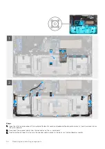

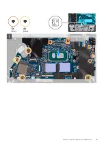


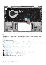


9. Align the screw holes on the right display hinge with the screw holes on the system board.
10. Replace the two screws (M2x3) to secure the right display hinge to the system board.
11. Align and place the display-cable bracket on the display-cable connector on the system board.
12. Replace the two screws (M2x3) to secure the display-cable bracket to the system board.
Next steps
1. Install the
.
2. Install the
.
3. Install the
.
4. Install the
.
5. Install the
, whichever applicable.
6. Install the
or the
, whichever applicable.
7. Install the
.
After working inside your computer
.
Power-adapter port
Removing the power-adapter port
Prerequisites
Before working inside your computer
.
2. Remove the
.
3. Remove the
or the
, whichever applicable.
4. Remove the
or the
, whichever applicable.
5. Remove the
.
6. Remove the
.
7. Remove the
.
8. Remove the
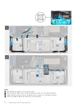
NOTE:
The system board can be removed with the thermal heat-sink attached to it in order to simplify the procedure
and preserve the thermal bond between the system board and the thermal heat-sink.
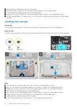
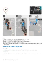
About this task
The following images indicate the location of the power-adapter port and provide a visual representation of the removal
procedure.
Removing and installing components
61
Summary of Contents for 3330
Page 12: ...12 Removing and installing components ...
Page 15: ...Removing and installing components 15 ...
Page 17: ...Removing and installing components 17 ...
Page 36: ...36 Removing and installing components ...
Page 37: ...Removing and installing components 37 ...
Page 40: ...40 Removing and installing components ...
Page 41: ...Removing and installing components 41 ...