background image

Quick Reference Guide

23

Desktop Computer


CAUTION: 

Before you begin any of the procedures in this section, follow the safety instructions in the 

Product 

Information Guide

.


CAUTION: 

To guard against electrical shock, always unplug your computer from the electrical outlet before 

removing the computer cover.

1

Follow the procedures in "Before You Begin" on page 19.

2

If you have installed a padlock through the padlock ring on the back panel, remove the padlock.

3

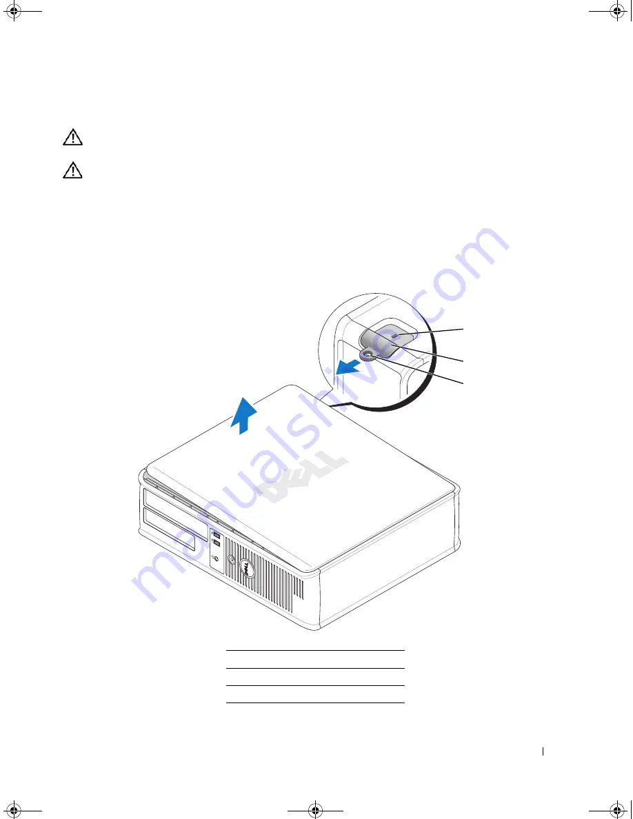
Slide the cover release latch back as you lift the cover.

4

Pivot the cover up using the hinge tabs as leverage points.

5

Remove the cover from the hinge tabs and set it aside on a soft nonabrasive surface.

1

security cable slot

2

cover release latch

3

padlock ring

2

1

3

book.book  Page 23  Tuesday, October 17, 2006  11:16 AM

Summary of Contents for 320LX

Page 1: ...w w w d e l l c o m s u p p o r t d e l l c o m Dell OptiPlex 320 Quick Reference Guide Models DCSM DCNE book book Page 1 Tuesday October 17 2006 11 16 AM ...

Page 2: ...change without notice 2006 Dell Inc All rights reserved Reproduction in any manner whatsoever without the written permission of Dell Inc is strictly forbidden Trademarks used in this text Dell OptiPlex and the DELL logo are trademarks of Dell Inc Microsoft and Windows are registered trademarks of Microsoft Corporation Intel and Pentium are registered trademarks of Intel Corporation Other trademark...

Page 3: ...ctors 18 Removing the Computer Cover 19 Before You Begin 20 Mini Tower Computer 21 Desktop Computer 23 Inside Your Computer 24 Mini Tower Computer 24 Desktop Computer 27 Solving Problems 30 Dell Diagnostics 30 System Lights 33 Diagnostic Lights 34 Beep Codes 37 Resolving Software and Hardware Incompatibilities 38 Using Microsoft Windows XP System Restore 38 Reinstalling Microsoft Windows XP 39 Usi...

Page 4: ...4 Contents book book Page 4 Tuesday October 17 2006 11 16 AM ...

Page 5: ...r Documentation and drivers are already installed on your computer You can use the CD to reinstall drivers see Reinstalling Drivers and Utilities in your online User s Guide to run the Dell Diagnostics see Dell Diagnostics on page 30 or to access your documentation Readme files may be included on your CD to provide the most current updates about technical changes to your computer or advanced techn...

Page 6: ... support dell com or contact support Enter the Express Service Code to direct your call when contacting support How to reinstall my operating system Operating System CD NOTE The Operating System CD may be optional and may not ship with your computer The operating system is already installed on your computer To reinstall your operating system use the Operating System CD See Reinstalling Microsoft W...

Page 7: ... drives Intel processors optical drives and USB devices DSS is necessary for correct operation of your Dell computer The software automatically detects your computer and operating system and installs the updates appropriate for your configuration Dell Support Website support dell com NOTE Select your region or business segment to view the appropriate support site To download Desktop System Softwar...

Page 8: ...r computer read the documentation that came with the device or software or contact the vendor to verify that the device or software is compatible with your computer and operating system You must complete all the steps to properly set up your computer See the appropriate figures that follow the instructions NOTICE Do not attempt to operate a PS 2 mouse and a USB mouse simultaneously 1 Connect the k...

Page 9: ...ert the monitor cable to avoid bending connector pins Tighten the thumbscrews on the cable connectors NOTE Some monitors have the video connector underneath the back of the screen See the documentation that came with your monitor for its connector locations Set Up Your Monitor 4 Connect the speakers book book Page 9 Tuesday October 17 2006 11 16 AM ...

Page 10: ...osely matches the AC power available in your location NOTICE In Japan the voltage selection switch must be set to the 115 V position even though the AC power available in Japan is 100 V 6 Verify that the voltage selection switch is set correctly for your location Your computer has a manual voltage selection switch Computers with a voltage selection switch on the back panel must be manually set to ...

Page 11: ...puter when you access the Dell Support website or call technical support 2 CD DVD drive Insert a CD or DVD if supported into this drive 3 floppy drive Insert a floppy disk into this drive 4 hard drive activity light This light flickers when the hard drive is in use 4 9 7 8 3 2 6 5 1 10 book book Page 11 Tuesday October 17 2006 11 16 AM ...

Page 12: ...ins solid to indicate different operating states No light The computer is turned off Steady green The computer is in a normal operating state Blinking green The computer is in a power saving mode Blinking or solid amber The computer is receiving electrical power but an internal power problem might exist See Power Problems in your online User s Guide To exit from a power saving mode press the power...

Page 13: ...w 1 cover release latch This latch allows you to open the computer cover 2 padlock ring Insert a padlock to lock the computer cover 3 power connector Insert the power cable into this connector 4 3 5 6 2 1 book book Page 13 Tuesday October 17 2006 11 16 AM ...

Page 14: ...ctor See Mini Tower Computer Back Panel Connectors on page 14 6 card slots Access connectors for any installed PCI and PCI Express cards 1 parallel connector Connect a parallel device such as a printer to the parallel connector If you have a USB printer plug it into a USB connector NOTE The integrated parallel connector is automatically disabled if the computer detects an installed card containing...

Page 15: ...playback device such as a cassette player CD player or VCR On computers with a sound card use the connector on the card 6 line out connector Use the green line out connector to attach headphones and most speakers with integrated amplifiers On computers with a sound card use the connector on the card 7 microphone connector Use the pink microphone connector to attach a personal computer microphone f...

Page 16: ...drive is being accessed 3 power button Press this button to turn on the computer NOTICE To avoid losing data do not turn off the computer by pressing the power button for 6 seconds or longer Instead perform an operating system shutdown NOTICE If your operating system has ACPI enabled when you press the power button the computer will perform an operating system shutdown 4 Dell badge This badge can ...

Page 17: ...For more information see Diagnostic Lights on page 34 7 link integrity light Green A good connection exists between a 10 Mbps network and the computer Orange A good connection exists between a 100 Mbps network and the computer Off The computer is not detecting a physical connection to the network 8 headphone connector Use the headphone connector to attach headphones 9 floppy drive Insert a floppy ...

Page 18: ...ock the computer cover 6 cover release latch Use this latch to open the computer cover 1 parallel connector Connect a parallel device such as a printer to the parallel connector If you have a USB printer plug it into a USB connector NOTE The integrated parallel connector is automatically disabled if the computer detects an installed card containing a parallel connector configured to the same addre...

Page 19: ...f network traffic may make this light appear to be in a steady on state 5 line in connector Use the blue line in connector to attach a record playback device such as a cassette player CD player or VCR On computers with a sound card use the connector on the card 6 line out connector Use the green line out connector to attach headphones and most speakers with integrated amplifiers On computers with ...

Page 20: ... a certified service technician should perform repairs on your computer Damage due to servicing that is not authorized by Dell is not covered by your warranty NOTICE When you disconnect a cable pull on its connector or on its strain relief loop not on the cable itself Some cables have a connector with locking tabs if you are disconnecting this type of cable press in on the locking tabs before you ...

Page 21: ...begin any of the procedures in this section follow the safety instructions in the Product Information Guide CAUTION To guard against electrical shock always unplug your computer from the electrical outlet before removing the computer cover 1 Follow the procedures in Before You Begin on page 19 2 If you have installed a padlock through the padlock ring on the back panel remove the padlock 3 Lay the...

Page 22: ...22 Quick Reference Guide 1 security cable slot 2 cover release latch 3 padlock ring 2 1 3 book book Page 22 Tuesday October 17 2006 11 16 AM ...

Page 23: ...computer cover 1 Follow the procedures in Before You Begin on page 19 2 If you have installed a padlock through the padlock ring on the back panel remove the padlock 3 Slide the cover release latch back as you lift the cover 4 Pivot the cover up using the hinge tabs as leverage points 5 Remove the cover from the hinge tabs and set it aside on a soft nonabrasive surface 1 security cable slot 2 cove...

Page 24: ...eference Guide Inside Your Computer Mini Tower Computer 1 CD DVD drive 4 system board 2 floppy drive 5 heat sink assembly 3 power supply 6 hard drive 1 3 4 6 2 5 book book Page 24 Tuesday October 17 2006 11 16 AM ...

Page 25: ...Quick Reference Guide 25 System Board Components 1 2 4 6 15 3 16 17 14 10 5 8 7 12 13 9 11 book book Page 25 Tuesday October 17 2006 11 16 AM ...

Page 26: ...ront panel connector FNT_PANEL 13 battery socket BATT 5 memory module connectors DIMM_1 DIMM_2 14 PCI Express x16 card connector 6 SATA drive connectors SATA0 SATA1 15 PCI card connectors 2 7 power connector POWER 16 floppy drive connector FLOPPY 8 CD DVD drive connector IDE 17 serial PS 2 connector PS2 SER2 9 SATA drive connectors SATA2 SATA3 Mini Tower Computer book book Page 26 Tuesday October ...

Page 27: ... are disabled RTCRST The real time clock has been enabled default setting The real time clock is being reset jumpered temporarily jumpered unjumpered 1 drive bay CD DVD floppy and hard drive 4 card slots 2 power supply 5 heat sink assembly 3 system board 6 front I O panel 1 2 3 4 5 6 1 1 book book Page 27 Tuesday October 17 2006 11 16 AM ...

Page 28: ...28 Quick Reference Guide System Board Components 1 2 4 6 15 3 16 17 14 10 5 8 7 12 13 11 9 book book Page 28 Tuesday October 17 2006 11 16 AM ...

Page 29: ... connector FNT_PANEL 13 battery socket BATT 5 memory module connectors DIMM_1 DIMM_2 14 PCI Express x16 card connector 6 serial ATA drive connectors SATA0 SATA1 15 PCI card connector 2 7 power connector POWER 16 floppy drive connector FLOPPY 8 CD DVD drive connector IDE 17 serial PS 2 connector PS2 SER2 9 serial ATA drive connectors SATA2 SATA3 Desktop Computer book book Page 29 Tuesday October 17...

Page 30: ...s Service Code ___________________________ Service Tag ___________________________ Dell Diagnostics CAUTION Before you begin any of the procedures in this section follow the safety instructions in the Product Information Guide When to Use the Dell Diagnostics If you experience a problem with your computer perform the checks in Solving Problems in your online User s Guide and run the Dell Diagnosti...

Page 31: ... 4 When the Dell Diagnostics Main Menu appears select the test you want to run Starting the Dell Diagnostics From the Drivers and Utilities CD 1 Insert the Drivers and Utilities CD 2 Shut down and restart the computer When the DELL logo appears press F12 immediately If you wait too long and the operating system logo appears continue to wait until you see the Microsoft Windows desktop Then shut dow...

Page 32: ... on your part Run Express Test first to increase the possibility of tracing the problem quickly Extended Test Performs a thorough check of devices This test typically takes an hour or more and requires you to answer questions periodically Custom Test Tests a specific device You can customize the tests you want to run Symptom Tree Lists the most common symptoms encountered and allows you to select ...

Page 33: ... page 34 If the computer does not boot contact Dell for technical assistance For information on contacting Dell see your online User s Guide Blinking yellow A power supply or system board failure has occurred Check Diagnostic Lights to see if the specific problem is identified see Diagnostic Lights on page 34 See Power Problems in your online User s Guide Solid green and a beep code during POST A ...

Page 34: ...r a successful POST the diagnostic lights do not indicate the cause of the problem NOTE The orientation of the diagnostic lights may vary depending on the system type The diagnostic lights can be either vertically or horizontally oriented Light Pattern Problem Description Suggested Resolution The computer is in a normal off condition or a possible pre BIOS failure has occurred The diagnostic light...

Page 35: ...problem persists contact Dell For information on contacting Dell see your online User s Guide A possible graphics card failure has occurred If the computer has a graphics card remove the card reinstall it and then restart the computer If the problem still exists install a graphics card that you know works and restart the computer If the problem persists or the computer has integrated graphics cont...

Page 36: ...r compatibility error exists Ensure that no special memory module memory connector placement requirements exist Verify that the memory modules that you are installing are compatible with your computer If the problem persists contact Dell For information on contacting Dell see your online User s Guide A failure has occurred This pattern also displays when you enter system setup and may not indicate...

Page 37: ...S checksum failure 3 2 4 Keyboard Controller test failure 1 2 1 Programmable interval timer failure 3 3 1 NVRAM power loss 1 2 2 DMA initialization failure 3 3 2 Invalid NVRAM configuration 1 2 3 DMA page register read write failure 3 3 4 Video Memory test failure 1 3 Video Memory test failure 3 4 1 Screen initialization failure 1 3 1 through 2 4 4 Memory not being properly identified or used 3 4 ...

Page 38: ...Support Center on page 7 NOTICE Make regular backups of your data files System Restore does not monitor your data files or recover them Creating a Restore Point 1 Click the Start button and click Help and Support 2 Click System Restore 3 Follow the instructions on the screen Restoring the Computer to an Earlier Operating State NOTICE Before you restore the computer to an earlier operating state sa...

Page 39: ...estarts click OK Enabling System Restore If you reinstall Windows XP with less than 200 MB of free hard disk space available System Restore is automatically disabled To verify that System Restore is enabled 1 Click the Start button and click Control Panel 2 Click Performance and Maintenance 3 Click System 4 Click the System Restore tab 5 Ensure that Turn off System Restore is unchecked Reinstallin...

Page 40: ... drive is the first drive detected by the computer To reinstall Windows XP you need the following items Dell Operating System CD Dell Drivers and Utilities CD To reinstall Windows XP perform all the steps in the following sections in the order in which they are listed The reinstallation process can take 1 to 2 hours to complete After you reinstall the operating system you must also reinstall the d...

Page 41: ...ete the setup depends on the size of the hard drive and the speed of your computer NOTICE Do not press any key when the following message appears Press any key to boot from the CD 6 When the Regional and Language Options screen appears select the settings for your location and click Next 7 Enter your name and organization optional in the Personalize Your Software screen and click Next 8 At the Com...

Page 42: ...t use the Drivers and Utilities CD while you are running Windows 1 Turn on the computer and allow it to boot to the Windows desktop 2 Insert the Drivers and Utilities CD into the CD drive If you are using the Drivers and Utilities CD for the first time on this computer the ResourceCD Installation window opens to inform you that the Drivers and Utilities CD is about to begin installation 3 Click OK...

Page 43: ...rmation 5 error messages beep codes 37 diagnostic lights 34 system lights 33 H hardware beep codes 37 conflicts 38 Dell Diagnostics 30 Hardware Troubleshooter 38 Help and Support Center 7 help file Windows Help and Support Center 7 I installing parts before you begin 20 IRQ conflicts 38 L labels Microsoft Windows 6 Service Tag 6 lights diagnostic 34 power 17 system 33 M motherboard See system boar...

Page 44: ...eshooting beep codes 37 conflicts 38 Dell Diagnostics 30 diagnostic lights 34 Hardware Troubleshooter 38 Help and Support Center 7 restore computer to previous operating state 38 system lights 33 U User s Guide 6 W warranty information 5 Windows XP Hardware Troubleshooter 38 Help and Support Center 7 reinstalling 6 39 setup 41 System Restore 38 book book Page 44 Tuesday October 17 2006 11 16 AM ...

Reviews: