


Service Manual
22
Chapter 5- TEST AND ADJUSTMENT
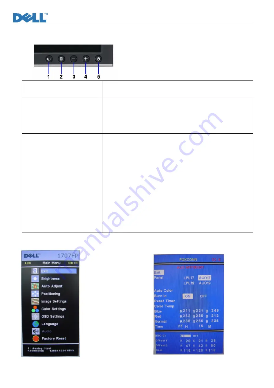
Function key Definitions
Power Switch with power LED
indicator
Power: On/Off, includes power indicator and Power ICON
Green- Active On
Amber- DPMS
Front Panel Controls
1- Input select: Select input signal
2- Menu: Call out OSD Menu and choose
3- (-): symbol molded into button, calls out brightness/Contrast, move
down the highlight bar.
4-(+)symbol molded into button, move up the highlight bar
Factory Modes Keys Function
Auto Color Balance
Purpose: Automatically calibrate chip ADC parameter by using chip
internal DAC.
Process: If we want to do “Auto Color Balance” again, please confirm
the following steps.
1)
Connect the VGA cable with the standard video pattern generator
and display the pattern with blackest and whitest colors.
2)
Press “Power Key”, to power off the monitor.
3)
Press “Menu Key” and “Up Key” simultaneously, and then press
“Power Key” to power on the monitor.
4)
Press “Menu Key”, choose “Factory Reset”, then “Factory”.
5)
Set Burn In Mode item to ON, then execute Auto Color item.
6)
After the “Auto Color Balance” process finished, go back to
“Factory Reset” of Main Menu, and press “All Setting” to exit
Factory Menu.
Factory Mode Introduction
Fig.1
Fig.2
Summary of Contents for 1907FPf
Page 1: ...Service Manual 0 Service Manual LCD Monitor 1907FPf ...
Page 55: ...Service Manual 54 ...
Page 56: ...Service Manual 55 Attachment 2 Schematic ...
Page 57: ...Service Manual 56 ...
Page 58: ...Service Manual 57 ...
Page 59: ...Service Manual 58 ...
Page 60: ...Service Manual 59 ...
Page 61: ...Service Manual 60 ...
Page 62: ...Service Manual 61 ...
Page 63: ...Service Manual 62 ...
Page 64: ...Service Manual 63 ...
Page 65: ...Service Manual 64 ...
Page 66: ...Service Manual 65 ...
Page 67: ...Service Manual 66 ...
Page 68: ...Service Manual 67 ...
Page 69: ...Service Manual 68 ...
Page 70: ...Service Manual 69 ...
Page 71: ...Service Manual 70 Attachment 3 PCB Layout Interface Board ...
Page 72: ...Service Manual 71 ...
Page 73: ...Service Manual 72 Power Inverter Board ...
Page 74: ...Service Manual 73 Keypad Board ...
Page 75: ...Service Manual 74 ...
Page 76: ...Service Manual 75 USB Control Board ...
Page 77: ...Service Manual 76 Inverter Control Board ...
Page 78: ...Service Manual 77 Power Control Board ...
Page 79: ...Service Manual 78 ...
Page 80: ...Service Manual 79 ...


