


2
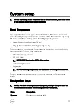
During POST, when the DELL logo is displayed, watch for the F2 prompt to
appear, and then press F2 immediately.
NOTE: The F2 prompt indicates that the keyboard is initialized. This
prompt can appear very quickly, so you must watch for it, and then
press F2. If you press F2 before the F2 prompt, this keystroke is lost. If
you wait too long and the operating system logo appears, continue to
wait until you see the desktop. Then, turn off your computer and try
again.
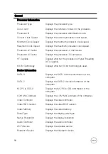
System setup options
NOTE: Depending on this computer and its installed devices, the items listed
in this section may or may not appear.
Table 3. System setup options—System information menu
General
System Information
BIOS Version
Displays the BIOS version number.
Service Tag
Displays the Service Tag of the computer.
Asset Tag
Displays the Asset Tag of the computer.
Ownership Tag
Displays the ownership tag of the computer.
Manufacture Date
Displays the manufacture date of the computer.
Ownership Date
Displays the ownership date of the computer.
Express Service Code
Displays the express service code of the computer.
Memory Information
Memory Installed
Displays the total computer memory installed.
Memory Available
Displays the total computer memory available.
Memory Speed
Displays the memory speed.
Memory Channel Mode
Displays single or dual channel mode.
Memory Technology
Displays the technology used for the memory.
DIMM A Size
Displays the DIMM A memory size.
DIMM B Size
Displays the DIMM B memory size.
79
Summary of Contents for 13 7000 2-in-1
Page 19: ...3 Lift the battery off the palm rest assembly 19 ...
Page 22: ...2 Peel the coin cell battery off the keyboard bracket 22 ...
Page 25: ...2 Lift the heat sink off the system board 25 ...
Page 28: ...4 Lift the fan off the keyboard bracket 28 ...
Page 31: ...5 Lift the right speaker off the palm rest assembly 31 ...
Page 34: ...3 Lift the power adapter port off the palm rest assembly 34 ...
Page 42: ...7 Gently lift the display assembly off the palm rest assembly 42 ...
Page 46: ...5 Lift the I O board off the palm rest assembly 46 ...
Page 54: ...14 Lift the system board off the palm rest assembly 54 ...
Page 62: ...5 Slide and lift the touchpad from the slot on the palm rest assembly 62 ...
Page 66: ...5 Lift the keyboard off the palm rest assembly 66 ...
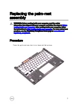
Page 70: ...Procedure After performing all the prerequisites we are left with the palm rest 70 ...