


Procedure A, Task 3: Customer's electrician
About this task
Note:
This task is performed by the customer's electrician.
Procedure
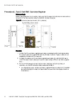
1. Working with the Dell EMC Customer Engineer, turn ON all the relevant circuit breakers in
customer-supplied PDU 2.
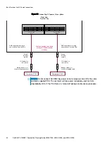
Verify that only power supply and/or SPS LEDs in power zone A are ON or flashing green in
every bay in the array.
CAUTION
The bay is incorrectly wired if all (power zone A and B) power supply and/or
SPS LEDs in a bay are ON or flashing green. Check that the AC power to both storage
bay power zones is not supplied by a single PDU (customer-supplied PDU 2). The wiring
must be corrected before moving on to the next step.
2. Turn OFF the relevant circuit breakers in customer-supplied PDU 2.
Verify that the power supply and/or SPS LEDs that turned green in the previous step
changed from green to OFF and/or flashing yellow. The yellow SPS lights flash for a
maximum of 5 minutes.
Note:
Power supplies connected to an SPS continue to have green lights ON while the
SPS yellow light continues to flash indicating the SPS is providing on-battery power.
3. Repeat step 1 and step 2 for power zone B and customer-supplied PDU 1.
4. Turn ON all the relevant circuit breakers in customer-supplied PDU 1 and customer-supplied
PDU 2.
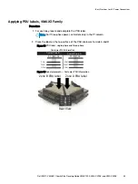
5. Label the PDUs as described in
Best Practices for AC Power Connections
96
Dell EMC
™
VMAX3
™
Family Site Planning Guide VMAX 100K, VMAX 200K, and VMAX 400K
Summary of Contents for VMAX3
Page 6: ...Contents 6 Dell EMC VMAX3 Family Site Planning Guide VMAX 100K VMAX 200K and VMAX 400K ...
Page 8: ...Figures 8 Dell EMC VMAX3 Family Site Planning Guide VMAX 100K VMAX 200K and VMAX 400K ...
Page 10: ...Tables 10 Dell EMC VMAX3 Family Site Planning Guide VMAX 100K VMAX 200K and VMAX 400K ...
Page 48: ...Position Bays 48 Dell EMC VMAX3 Family Site Planning Guide VMAX 100K VMAX 200K and VMAX 400K ...


