


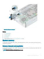
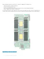
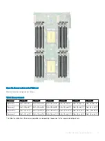


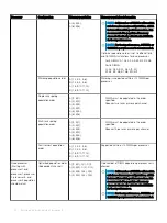


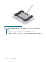

Figure 52. Memory sockets on the PEM board
Memory channels are organized as follows:
Table 7. Memory channels
Processor
Channel 0
Channel 1
Channel 2
Channel 3
Channel 4
Channel 5
Processor 1
Slots A1 and A7
Slots A2 and A8
Slots A3 and A9
Slots A4 and A10
Slots A5 and A11
Slots A6 and A12
Processor 2
Slots B1 and B7
Slots B2 and B8
Slots B3 and B9
Slots B4 and B10
Slots B5 and B11
Slots B6 and B12
Processor 3
Slots C1 and C7
Slots C2 and C8
Slots C3 and C9
Slots C4 and C10
Slots C5 and C11
Slots C6 and C12
Processor 4
Slots D1 and D7
Slots D2 and D8
Slots D3 and D9
Slots D4 and D10
Slots D5 and D11
Slots D6 and D12
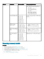
The following table shows the memory populations and operating frequencies for the supported configurations:
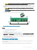
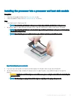
Installing and removing sled components
77