background image

Steps

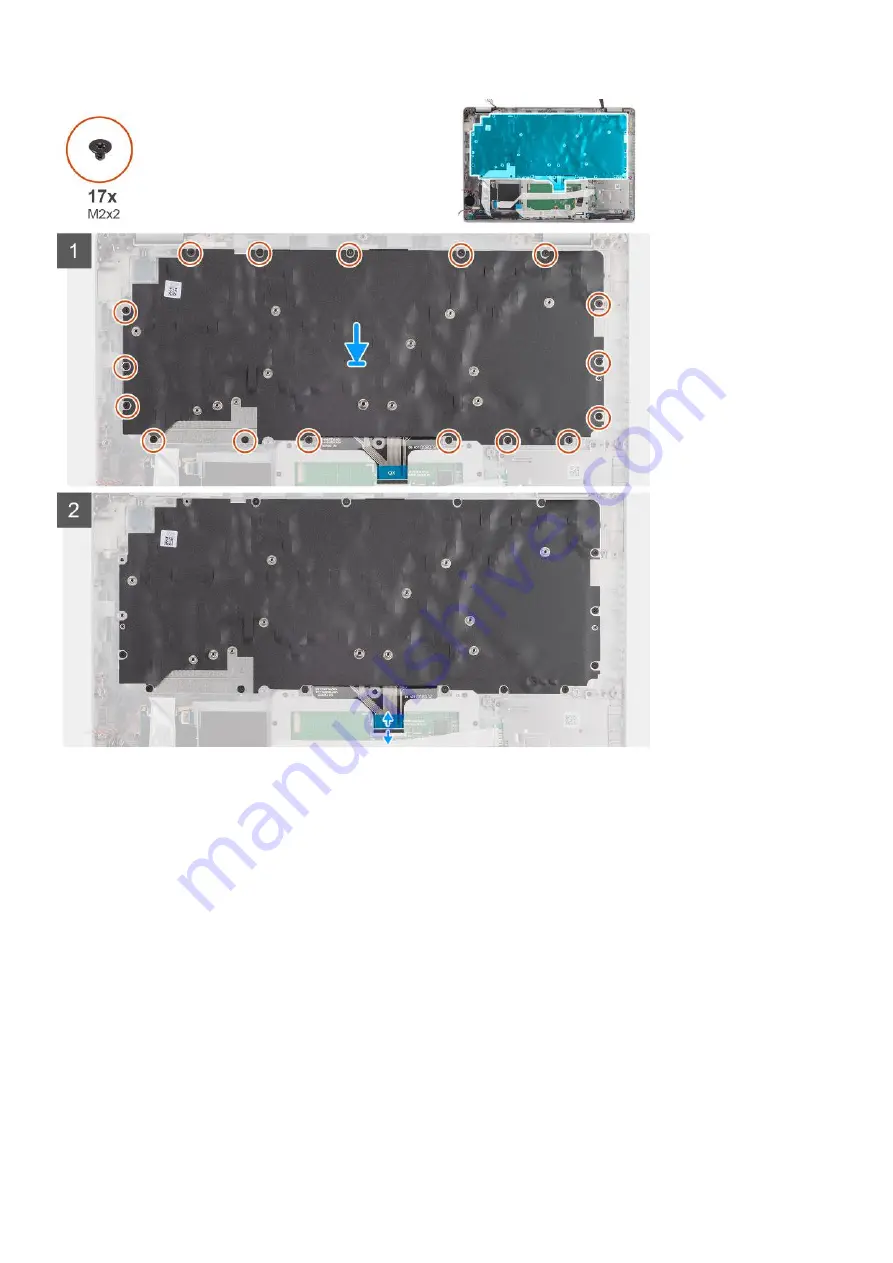
1. Align and place the keyboard on the keyboard bracket.
2. Replace the ten screws (M2x2) to secure the keyboard to the keyboard bracket.

Next steps

1. Install the 

keyboard assembly

.

2. Install the 

system board

.

3. Install the 

assembly inner frame

.

4. Install the 

battery

.

5. Install the 

solid-state drive

.

6. Install the 

memory module

.

7. Install the 

WWAN card

.

8. Install the 

WLAN card

.

9. Install the 

base cover

.

10. Install the 

microSD card

.

11. Install the 

SIM card

.

12. Follow the procedure in 

After working inside your computer

.

Removing and installing components

59

Summary of Contents for Latitude 5420

Page 1: ...Latitude 5420 Service Manual Regulatory Model P137G Regulatory Type P137G001 P137G002 January 2021 Rev A00 ...

Page 2: ...ential damage to hardware or loss of data and tells you how to avoid the problem WARNING A WARNING indicates a potential for property damage personal injury or death 2020 Dell Inc or its subsidiaries All rights reserved Dell EMC and other trademarks are trademarks of Dell Inc or its subsidiaries Other trademarks may be trademarks of their respective owners ...

Page 3: ...criber Identity Module SIM card 15 Micro Secure Digital SD Card 17 Base cover 19 WLAN card 22 WWAN card 25 Solid state drive 27 Memory modules 31 Battery 32 Battery cable 36 Assembly inner frame 38 LED board 41 Heat sink 43 Speakers 45 System board 47 Power button board 51 Smart card reader 53 Keyboard assembly 55 Keyboard bracket 57 Display assembly 60 Display bezel 64 Display panel 66 Camera mic...

Page 4: ...word 98 Deleting or changing an existing system setup password 98 Chapter 6 Troubleshooting 99 Dell SupportAssist Pre boot System Performance Check diagnostics 99 Running the SupportAssist Pre Boot System Performance Check 99 System diagnostic lights 100 Recovering the operating system 101 Flashing BIOS USB key 101 Flashing the BIOS 102 WiFi power cycle 102 Flea power release 102 Chapter 7 Getting...

Page 5: ...optical disc from your computer if applicable Safety precautions The safety precautions chapter details the primary steps to be taken before performing any disassembly instructions Observe the following safety precautions before you perform any installation or break fix procedures involving disassembly or reassembly Turn off the system and all attached peripherals Disconnect the system and all att...

Page 6: ...The wrist strap should be secure and in full contact with your skin and ensure that you remove all jewelry such as watches bracelets or rings prior to bonding yourself and the equipment Enter service mode Service Mode allows you to immediately cut the power from the computer without disconnecting the battery cable or removing the battery from the computer Steps 1 Shut down the computer and disconn...

Page 7: ... the ready to proceed message appears on the screen press any key to proceed The system emits three short beeps and shuts down immediately NOTE If the AC adapter has not been disconnected a message prompting you to remove the AC adapter appears on the screen Remove the AC adapter and then press any key to continue the Service Mode procedure Working inside your computer 7 ...

Page 8: ...ST No Video symptom with a beep code emitted for missing or nonfunctional memory Intermittent Intermittent failures represent approximately 80 percent of ESD related failures The high rate of intermittent failures means that most of the time when damage occurs it is not immediately recognizable The DIMM receives a static shock but the tracing is merely weakened and does not immediately produce out...

Page 9: ...nsitive devices such as plastic heat sink casings away from internal parts that are insulators and often highly charged Working Environment Before deploying the ESD Field Service kit assess the situation at the customer location For example deploying the kit for a server environment is different than for a desktop or portable environment Servers are typically installed in a rack within a data cent...

Page 10: ...al devices peripherals or cables you removed before working on your computer 3 Replace any media cards discs or any other parts that you removed before working on your computer 4 Connect your computer and all attached devices to their electrical outlets 5 Turn on your computer 10 Working inside your computer ...

Page 11: ...2 Major components of your computer 11 ...

Page 12: ...Major components of your computer 12 Major components of your computer ...

Page 13: ...y inner frame 6 System board 7 Keyboard assembly 8 Palm rest assembly 9 Display assembly 10 Battery LED board 11 Coin cell battery 12 Power button fingerprint board 13 Heat sink 14 Solid state drive 15 WWAN card 16 WLAN card Major components of your computer 13 ...

Page 14: ...ce them in a screw storage box This is to ensure that the correct number of screws and correct screw type is restored when the component is replaced NOTE Some systems have magnetic surfaces Ensure that the screws are not left attached to such surface when replacing a component NOTE Screw color may vary with the configuration ordered Table 1 Latitude 5420 screw list Component Screw type Quantity Sc...

Page 15: ...rest assembly 4 Display hinge M2 5x3 display hinge to display back cover 4 Display panel M2 5x3 2 Disassembly and reassembly NOTE The images in this document may differ from your computer depending on the configuration you ordered Subscriber Identity Module SIM card Removing the SIM card Prerequisites 1 Follow the procedure in Before working inside your computer 2 Enter service mode NOTE SIM card ...

Page 16: ...e slot on the computer 3 Remove the SIM card from the SIM card tray 4 Slide the SIM card tray into the slot until it clicks into place Installing the SIM card Prerequisites If you are replacing a component remove the existing component before performing the installation procedure NOTE SIM card or SIM card tray removal is only available on systems that are shipped with WWAN module Hence removing pr...

Page 17: ...and carefully slide it in 5 Slide the SIM card tray into the slot until it clicks into place Next steps 1 Follow the procedure in After working inside your computer Micro Secure Digital SD Card Removing the microSD card Prerequisites 1 Follow the procedure in Before working inside your computer 2 Enter service mode About this task The following images indicate the location of the microSD card and ...

Page 18: ... microSD card About this task The following image indicates the location of the microSD card and provides a visual representation of the installation procedure Steps 1 Align the microSD card to its slot on the computer 2 Slide the microSD card into the slot until it clicks into place 18 Removing and installing components ...

Page 19: ...uisites 1 Follow the procedure in Before working inside your computer 2 Enter service mode 3 Remove the SIM card 4 Remove the microSD card About this task The following images indicate the location of the base cover and provide a visual representation of the removal procedure Removing and installing components 19 ...

Page 20: ...yboard assembly 3 Grasp the left side and the right side of the base cover and remove the base cover from the palm rest assembly and keyboard assembly Installing the base cover Prerequisites If you are replacing a component remove the existing component before performing the installation procedure About this task The following images indicate the location of the base cover and provide a visual rep...

Page 21: ...Removing and installing components 21 ...

Page 22: ...stall the microSD card 2 Install the SIM card 3 Follow the procedure in After working inside your computer WLAN card Removing the WLAN card Prerequisites 1 Follow the procedure in Before working inside your computer 2 Enter service mode 3 Remove the SIM card 4 Remove the microSD card 5 Remove the base cover About this task The following images indicate the location of the WLAN card and provide a v...

Page 23: ...and remove the WLAN card bracket off the WLAN card 3 Disconnect the antenna cables from the WLAN card 4 Slide and remove the WLAN card from the WLAN card slot Installing the WLAN card Prerequisites If you are replacing a component remove the existing component before performing the installation procedure About this task The following image indicates the location of the WLAN card and provides a vis...

Page 24: ... the tab on the WLAN card slot NOTE When removing the WLAN card from the computer if the adhesive pad which helps secure the WLAN card in place is removed from the computer along with the WLAN card adhere it back to the computer 4 Slide the wireless card at an angle into the WLAN card slot 5 Replace the screw M2x2 5 to secure the WLAN card bracket to the WLAN card Next steps 1 Install the base cov...

Page 25: ...task The following image indicates the location of the WWAN card and provide a visual representation of the removal procedure Steps 1 Remove the screw M2x2 5 that secures the WWAN card bracket to the WWAN card 2 Slide and remove the WWAN card bracket off the WWAN card 3 Disconnect the antenna cables from the WWAN card 4 Slide and remove the WWAN card from the WWAN card slot Removing and installing...

Page 26: ...he antenna cables to the WWAN card The following table provides the antenna cable color scheme Table 3 Antenna cable color scheme Connectors on the WWAN card Antenna cable color Main white triangle White Auxiliary black triangle Black 2 Place the WWAN card bracket on the WWAN card 3 Align the notch on the WWAN card with the tab on the WWAN slot 4 Slide the WWAN card at an angle into the WWAN slot ...

Page 27: ...Remove the microSD card 5 Remove the base cover About this task The following images indicate the location of the M 2 2280 solid state drive and provide a visual representation of the removal procedure Steps 1 Remove the two screws M2x3 that secures the M 2 2280 solid state drive thermal plate to the system board 2 Lift the M 2 2280 solid state drive thermal plate off the system board 3 Slide and ...

Page 28: ...into the solid state drive slot on the system board 3 Align the screw holes on the M 2 2280 solid state drive thermal plate with the screw holes on the system board 4 Replace the two screws M2x3 that secures the M 2 2280 solid state drive thermal plate to the system board Next steps 1 Install the base cover 2 Install the microSD card 3 Install the SIM card 4 Follow the procedure in After working i...

Page 29: ...ff the system board 4 Flip the M 2 2230 solid state drive holder and remove the single screw M2x3 that secure the M 2 2230 solid state drive to the M 2 2230 solid state drive holder 5 Slide and remove the M 2 2230 solid state drive from the M 2 2230 solid state drive holder Installing the M 2 2230 solid state drive Prerequisites If you are replacing a component remove the existing component before...

Page 30: ... 2 2230 solid state drive 4 Replace the single screw M2x3 that secure the M 2 2230 solid state drive holder to the system board 5 Align the screw holes on the M 2 2230 solid state drive thermal pad with the screw holes on the M 2 2230 solid state drive holder 6 Replace the two screws M2x2 5 that secures the M 2 2230 solid state drive thermal pad to the M 2 2230 solid state drive holder Next steps ...

Page 31: ...g your fingertips spread apart the securing clips on the memory module slot until the memory module pops up 2 Slide and remove the memory module from the memory module slot NOTE Repeat step 1 and 2 if there are two memory modules Installing the memory modules Prerequisites If you are replacing a component remove the existing component before performing the installation procedure About this task Th...

Page 32: ...he battery completely before removing it Disconnect the AC power adapter from the system and operate the computer solely on battery power the battery is fully discharged when the computer no longer turns on when the power button is pressed Do not crush drop mutilate or penetrate the battery with foreign objects Do not expose the battery to high temperatures or disassemble battery packs and cells D...

Page 33: ...e cover NOTE If battery is disconnected from system board for service then there is a delay during system boot up as the system undergoes RTC battery reset About this task The following images indicate the location of the 3 cell battery and provide a visual representation of the removal procedure Steps 1 Disconnect the battery cable from the system board if it was not disconnected earlier 2 Remove...

Page 34: ... cable to the system board Next steps 1 Install the base cover 2 Install the microSD card 3 Install the SIM card 4 Follow the procedure in After working inside your computer Removing the 4 cell battery Prerequisites 1 Follow the procedure in Before working inside your computer 2 Enter service mode 3 Remove the SIM card 4 Remove the microSD card 5 Remove the base cover NOTE If battery is disconnect...

Page 35: ...g the 4 cell battery Prerequisites If you are replacing a component remove the existing component before performing the installation procedure About this task The following image indicates the location of the 4 cell battery and provides a visual representation of the installation procedure NOTE If battery is disconnected from system board for service then there is a delay during system boot up as ...

Page 36: ...mputer Battery cable Removing the battery cable Prerequisites 1 Follow the procedure in Before working inside your computer 2 Enter service mode 3 Remove the SIM card 4 Remove the microSD card 5 Remove the base cover 6 Remove the battery NOTE If battery is disconnected from system board for service then there is a delay during system boot up as the system undergoes RTC battery reset About this tas...

Page 37: ...battery cable away from the battery Installing the battery cable Prerequisites If you are replacing a component remove the existing component before performing the installation procedure About this task The following image indicates the location of the battery cable and provides a visual representation of the installation procedure Removing and installing components 37 ...

Page 38: ... in After working inside your computer Assembly inner frame Removing the assembly inner frame Prerequisites 1 Follow the procedure in Before working inside your computer 2 Enter service mode 3 Remove the SIM card 4 Remove the microSD card 5 Remove the base cover 6 Remove the battery 7 Remove the WLAN card 8 Remove the WWAN card About this task The following image indicates the location of the asse...

Page 39: ...ard and unroute the cable from the routing guides on the assembly inner frame 4 Remove the three screws M2x5 that secures the assembly inner frame to the system board and the palm rest assembly 5 Remove the seven screws M2x3 that secure the assembly inner frame to the system board and the palm rest assembly 6 Lift the assembly inner frame off the system board and the palm rest assembly Removing an...

Page 40: ...omponent remove the existing component before performing the installation procedure About this task The following image indicates the location of the assembly inner frame and provides a visual representation of the installation procedure 40 Removing and installing components ...

Page 41: ...routing guide on the assembly inner frame and connect the speaker cable to the connector on the system board 6 Route the antennas cable through the routing guides on the assembly inner frame Next steps 1 Install the WWAN card 2 Install the WLAN card 3 Install the battery 4 Install the base cover 5 Install the microSD card 6 Install the SIM card 7 Follow the procedure in After working inside your c...

Page 42: ... board and cable away from the palm rest assembly Installing the LED board Prerequisites If you are replacing a component remove the existing component before performing the installation procedure About this task The following image indicates the location of the LED board and provides a visual representation of the installation procedure 42 Removing and installing components ...

Page 43: ...the procedure in After working inside your computer Heat sink Removing the heat sink Prerequisites 1 Follow the procedure in before working inside your computer CAUTION The heat sink may become hot during normal operation Allow sufficient time for the heat sink to cool before you touch it 2 Enter service mode 3 Remove the SIM card 4 Remove the microSD card 5 Remove the base cover 6 Remove the batt...

Page 44: ...he heat sink to the system board 4 Lift the heat sink off the system board Installing the heat sink Prerequisites If you are replacing a component remove the existing component before performing the installation procedure About this task The following image indicates the location of the heat sink and provides a visual representation of the installation procedure 44 Removing and installing componen...

Page 45: ...e battery 2 Install the base cover 3 Install the microSD card 4 Install the SIM card 5 Follow the procedure in After working inside your computer Speakers Removing the speaker Prerequisites 1 Follow the procedure in Before working inside your computer 2 Enter service mode 3 Remove the SIM card 4 Remove the microSD card 5 Remove the base cover 6 Remove the battery About this task The following imag...

Page 46: ...t the speakers along with the cable off the palm rest assembly Installing the speaker Prerequisites If you are replacing a component remove the existing component before performing the installation procedure About this task The following image indicates the location of the speaker and provides a visual representation of the installation procedure 46 Removing and installing components ...

Page 47: ...the procedure in After working inside your computer System board Removing the system board Prerequisites 1 Follow the procedure in Before working inside your computer 2 Enter service mode 3 Remove the SIM card 4 Remove the microSD card 5 Remove the base cover 6 Remove the WLAN card 7 Remove the WWAN card 8 Remove the memory module 9 Remove the solid state drive 10 Remove the battery 11 Remove the ...

Page 48: ...he system board NOTE For the models shipped with a fingerprint reader disconnect the fingerprint reader cable from the connector on the system board before removing the system board from the palm rest assembly and keyboard assembly 1 Remove the two screws M2x3 that secure the eDP display cable bracket to the system board 2 Lift the eDP display cable bracket away from the system 3 Peel the tape tha...

Page 49: ...m board 8 Remove the three screws M2x5 that secure the USB Type C bracket to the system board 9 Lift off the USB Type C bracket off the system board 10 Remove the four screws M2x5 that secure the system board to the palm rest assembly and keyboard assembly 11 Lift the system board off the palm rest assembly and keyboard assembly Installing the system board Prerequisites If you are replacing a comp...

Page 50: ...onnect the touch pad cable to the system board and close the latch to secure the cable to the system board 7 Route the coin cell battery cable under the system board and connect the coin cell battery cable to the connector on the system board 8 Route the display and eDP display cable through the routing guide on the system board 9 Connect the eDP display cable to the connector on the system board ...

Page 51: ...ve the memory module 9 Remove the solid state drive 10 Remove the battery 11 Remove the assembly inner frame 12 Remove the system board About this task The following images indicate the location of the power button board and provide a visual representation of the removal procedure Steps 1 Remove the two screws M2x2 5 that secure the power button board to the palm rest assembly 2 Lift the power but...

Page 52: ...ace the two screws M2x2 5 that secure the power button board to the palm rest assembly Next steps 1 Install the system board 2 Install the assembly inner frame 3 Install the battery 4 Install the solid state drive 5 Install the memory module 6 Install the WWAN card 7 Install the WLAN card 8 Install the base cover 9 Install the microSD card 10 Install the SIM card 11 Follow the procedure in After w...

Page 53: ...d 4 Remove the microSD card 5 Remove the base cover 6 Remove the WLAN card 7 Remove the WWAN card 8 Remove the solid state drive 9 Remove the battery 10 Remove the assembly inner frame About this task The following images indicate the location of the smart card reader and provide a visual representation of the removal procedure Removing and installing components 53 ...

Page 54: ...ing a component remove the existing component before performing the installation procedure About this task The following image indicates the location of the smart card reader and provides a visual representation of the installation procedure Steps 1 Align and place the smart card reader on the palm rest assembly 2 Replace the four screws M2x2 5 that secure the smart card reader to the palm rest as...

Page 55: ...erequisites 1 Follow the procedure in Before working inside your computer 2 Enter service mode 3 Remove the SIM card 4 Remove the microSD card 5 Remove the base cover 6 Remove the WLAN card 7 Remove the WWAN card 8 Remove the memory module 9 Remove the solid state drive 10 Remove the battery 11 Remove the assembly inner frame 12 Remove the system board About this task The following images indicate...

Page 56: ...the keyboard assembly off the palm rest assembly Installing the keyboard assembly Prerequisites If you are replacing a component remove the existing component before performing the installation procedure About this task The following image indicates the location of the keyboard assembly and provides a visual representation of the installation procedure 56 Removing and installing components ...

Page 57: ...2 Install the assembly inner frame 3 Install the battery 4 Install the solid state drive 5 Install the memory module 6 Install the WWAN card 7 Install the WLAN card 8 Install the base cover 9 Install the microSD card 10 Install the SIM card 11 Follow the procedure in After working inside your computer Keyboard bracket Removing the keyboard bracket Prerequisites 1 Follow the procedure in Before wor...

Page 58: ...ocation of the keyboard bracket and provide a visual representation of the removal procedure Steps 1 Remove the six screws M2x2 that secure the keyboard to the keyboard bracket 2 Remove the keyboard from the keyboard bracket Installing the keyboard bracket Prerequisites If you are replacing a component remove the existing component before performing the installation procedure About this task The f...

Page 59: ...sembly 2 Install the system board 3 Install the assembly inner frame 4 Install the battery 5 Install the solid state drive 6 Install the memory module 7 Install the WWAN card 8 Install the WLAN card 9 Install the base cover 10 Install the microSD card 11 Install the SIM card 12 Follow the procedure in After working inside your computer Removing and installing components 59 ...

Page 60: ... your computer 2 Enter service mode 3 Remove the SIM card 4 Remove the microSD card 5 Remove the base cover 6 Remove the battery About this task The following images indicate the location of the display assembly and provide a visual representation of the removal procedure 60 Removing and installing components ...

Page 61: ...ket to the system board 2 Lift the eDP cable bracket away from the system 3 Peel the tape that secures the display cable to the system board 4 Using the pull tab disconnect the display cable from the connector on the system board Removing and installing components 61 ...

Page 62: ...the computer on a flat surface 8 Remove the four screws M2 5x3 that secure the display hinges to the system board 9 Remove the display assembly off the computer Installing the display assembly Prerequisites If you are replacing a component remove the existing component before performing the installation procedure About this task The following image indicates the location of the display assembly an...

Page 63: ...ecure the cables to the system board 5 Route the display and eDP cable through the routing guide on the system board 6 Connect the eDP cable to the connector on the system board 7 Connect the display cable to the connector on the system board 8 Adhere the tape that secures the display cable to the system board 9 Align the screw holes on the eDP cable bracket with the screw holes on the system boar...

Page 64: ... Remove the battery 7 Remove the display assembly About this task The following images indicate the location of the display bezel and provide a visual representation of the removal procedure Steps NOTE The display bezel is adhered to the display panel with adhesive Insert a plastic scribe into the recesses near both hinge caps to start the prying process to release the display bezel Pry along the ...

Page 65: ...ling the display bezel Prerequisites If you are replacing a component remove the existing component before performing the installation procedure About this task The following image indicates the location of the display bezel and provides a visual representation of the installation procedure Steps 1 Align and place the display bezel on the display assembly 2 Gently snap the display bezel into place...

Page 66: ... mode 3 Remove the SIM card 4 Remove the microSD card 5 Remove the base cover 6 Remove the battery 7 Remove the display assembly 8 Remove the display bezel About this task The following images indicate the location of the display panel and provide a visual representation of the removal procedure 66 Removing and installing components ...

Page 67: ...Removing and installing components 67 ...

Page 68: ... Lift and open the display panel to access the display cable 3 Peel the conductive tape on the display cable connector 4 Open the latch and disconnect the cable from the connector on the display panel 5 Lift the display panel away from the display back cover Installing the display panel Prerequisites If you are replacing a component remove the existing component before performing the installation ...

Page 69: ...Removing and installing components 69 ...

Page 70: ...70 Removing and installing components ...

Page 71: ...TE Ensure that the display panel tabs are inserted into the slots on the display cover 4 Replace the two screws M2 5x3 to secure the display panel to the display back cover Next steps 1 Install the display bezel 2 Install the display assembly 3 Install the battery 4 Install the base cover 5 Install the microSD card 6 Install the SIM card 7 Follow the procedure in After working inside your computer...

Page 72: ... microphone module indicated by an arrow etched on the grounding foil that should be used to begin the prying process Starting from the recess at the bottom edge of the camera microphone module pry up the camera microphone module ensuring that the two tiny pegs used to secure the camera microphone module in place is not damaged throughout the prying process 1 Peel the two conductive tapes that sec...

Page 73: ...s 2 Install the display panel 3 Install the display bezel 4 Install the display assembly 5 Install the battery 6 Install the base cover 7 Install the microSD card 8 Install the SIM card 9 Follow the procedure in After working inside your computer eDP display cable Removing the eDP cable Prerequisites 1 Follow the procedure in Before working inside your computer 2 Enter service mode 3 Remove the SI...

Page 74: ...tape and unroute the eDP display cable to release it from adhesive and lift the eDP display cable from the display back cover Installing the eDP cable Prerequisites If you are replacing a component remove the existing component before performing the installation procedure About this task The following image indicates the location of the eDP cable and provides a visual representation of the install...

Page 75: ...ver Next steps 1 Install the display panel 2 Install the display bezel 3 Install the display assembly 4 Install the base cover 5 Install the microSD card 6 Install the SIM card 7 Follow the procedure in After working inside your computer Sensor board Removing the sensor board Prerequisites 1 Follow the procedure in Before working inside your computer 2 Enter service mode Removing and installing co...

Page 76: ... the sensor board and provide a visual representation of the removal procedure Steps 1 Open the latch and disconnect the display cable from connector on the sensor board 2 Gently lift the sensor board away from the display back cover Installing the sensor board About this task The following images indicate the location of the sensor board and provide a visual representation of the removal procedur...

Page 77: ... card 8 Follow the procedure in After working inside your computer Display hinges Removing the display hinges Prerequisites 1 Follow the procedure in Before working inside your computer 2 Enter service mode 3 Remove the SIM card 4 Remove the microSD card 5 Remove the base cover 6 Remove the display assembly 7 Remove the display bezel 8 Remove the display panel About this task The following images ...

Page 78: ...e display back cover 4 Lift and remove the left hinge from the display back cover Installing the display hinges Prerequisites If you are replacing a component remove the existing component before performing the installation procedure About this task The following images indicate the location of the display hinges and provides a visual representation of the installation procedure 78 Removing and in...

Page 79: ...ht hinge with the screw hole on the display back cover 4 Replace the two screws M2 5x3 to secure the right hinge to the display back cover Next steps 1 Install the display panel 2 Install the display bezel 3 Install the display assembly 4 Install the base cover 5 Install the microSD card 6 Install the SIM card 7 Follow the procedure in After working inside your computer Removing and installing com...

Page 80: ...one module 10 Remove the eDP display cable 11 Remove the sensor board 12 Remove the display hinges About this task The following images indicate the location of the display back cover and provide a visual representation of the removal procedure Steps After performing the steps in the pre requisites we are left with the display back cover Installing the display back cover Prerequisites If you are r...

Page 81: ...5 Install the display panel 6 Install the display bezel 7 Install the display assembly 8 Install the base cover 9 Install the microSD card 10 Install the SIM card 11 Follow the procedure in After working inside your computer Dummy SIM card slot filler Removing the dummy SIM card slot filler Prerequisites 1 Follow the procedure in Before working inside your computer 2 Enter service mode 3 Remove th...

Page 82: ...ed and then reinstalled when replacing the palm rest assembly The following image indicates the dummy SIM card slot filler and provides a visual representation of the dummy SIM card slot filler removal procedure Steps 1 Push the dummy SIM card slot filler from the top side of the palm rest assembly 2 Gently lift the dummy SIM card slot filler out of the palm rest assembly Installing the dummy SIM ...

Page 83: ... assembly 2 Install the display assembly 3 Install the keyboard assembly 4 Install the power button board 5 Install the smart card reader 6 Install the LED board 7 Install the system board 8 Install the assembly inner frame 9 Install the battery 10 Install the solid state drive 11 Install the memory module 12 Install the WWAN card 13 Install the WLAN card 14 Install the base cover 15 Install the m...

Page 84: ... state drive 10 Remove the battery 11 Remove the assembly inner frame 12 Remove the system board 13 Remove the smart card reader 14 Remove the LED board 15 Remove the power button board 16 Remove the keyboard assembly 17 Remove the display assembly About this task The following image indicates the palm rest assembly and provides a visual representation of the removal procedure Steps After performi...

Page 85: ...alm rest assembly on a flat surface 2 Remove the dummy SIM card filler for the non WWAN LTE configuration Next steps 1 Install the display assembly 2 Install the keyboard assembly 3 Install the power button board 4 Install the smart card reader 5 Install the LED board 6 Install the system board 7 Install the assembly inner frame 8 Install the battery 9 Install the solid state drive 10 Install the ...

Page 86: ...mputer starts to download and install SupportAssist NOTE Review on screen instructions for browser specific instructions 8 Click View Drivers for My System 9 Click Download and Install to download and install all driver updates detected for your computer 10 Select a location to save the files 11 If prompted approve requests from User Account Control to make changes on the system 12 The application...

Page 87: ...equence System setup options System and setup password BIOS overview The BIOS manages data flow between the computer s operating system and attached devices such as hard disk video adapter keyboard mouse and printer Entering BIOS setup program About this task Turn on or restart your computer and press F2 immediately Navigation keys NOTE For most of the System Setup options changes that you make ar...

Page 88: ...ag Displays the Ownership Tag of the computer Signed Firmware Update Displays whether the Signed Firmware Update is enabled on your computer Battery Information Primary Displays that battery is primary Battery Level Displays the battery level of the computer Battery State Displays the battery state of the computer Health Displays the battery health of the computer AC Adapter Displays whether the A...

Page 89: ...r LOM MAC Address Displays the LAN On Motherboard LOM MAC address of the computer Pass Through MAC Address Displays the pass through MAC address of the computer Cellular Device Displays the M 2 PCIe SSD information of the computer Table 5 System setup options Boot Configuration menu Boot Configuration Boot Sequence Boot mode Displays the boot mode Boot Sequence Displays the boot sequence Secure Di...

Page 90: ... through a Thunderbolt adapter to execute the PCIe devices UEFI Option ROM if present during pre boot By default the Enable Thunderbolt and PCIe behind TBT pre boot modules option is disabled Disable USB4 PCIE Tunneling Disable the USB4 PCIE Tunneling option By default the option is disabled Video Power only on Type C Ports Enable or disable the Type C port functionality to video or only power By ...

Page 91: ... Card option is enabled Secure Digital SD Card Read Only Mode Enable or disable the SD card read only mode By default the Secure Digital SD Card Read Only Mode option is not enabled Table 8 System setup options Display menu Display Display Brightness Brightness on battery power Enable to set screen brightness when the computer is running on battery power Brightness on AC power Enable to set screen...

Page 92: ...s WWAN By default the option is disabled HTTPs Boot Feature HTTPs Boot Enable or disable the HTTPs Boot feature By default the HTTPs Boot option is enabled HTTPs Boot Mode With Auto Mode the HTTPs Boot extracts Boot URL from the DHCP With Manual Mode the HTTPs Boot reads Boot URL from the user provided data By default the Auto Mode option is enabled Table 10 System setup options Power menu Power B...

Page 93: ...ed Attestation Enable Enables to control whether the Trusted Platform Module TPM Endorsement Hierarchy is available to the operating system By default the Attestation Enable option is enabled Key Storage Enable Enables to control whether the Trusted Platform Module TPM Storage Hierarchy is available to the operating system By default the Key Storage Enable option is enabled SHA 256 BIOS and the TP...

Page 94: ...ve at least one upper case letter By default the option is disabled Lower Case Letter Reinforces password must have at least one lower case letter By default the option is disabled Digit Reinforces password must have at least one digit By default the option is disabled Special Character Reinforces password must have at least one special character By default the option is disabled Minimum Character...

Page 95: ... enabled BISOConnect Enable or disable cloud Service OS recovery if the main operating system fails to boot with the number of failures equal to or greater than the value specified by the Auto OS Recovery Threshold setup option and local Service OS does not boot or is not installed By default the option is enabled Dell Auto OS Recovery Threshold Controls the automatic boot flow for SupportAssist S...

Page 96: ...Enable Adapter Warnings Enable or disable the warning messages during boot when the adapters with less power capacity are detected By default the option is enabled Warning and Errors Enable or disable the action to be done when a warning or error is encountered By default the Prompt on Warnings and Errors option is enabled Fastboot Enable to set the speed of the boot process By default the Minimal...

Page 97: ... BIOS Event Log Clear Bios Event Log Display BIOS events By default the Keep option is enabled Thermal Event Log Clear Thermal Event Log Display Thermal events By default the Keep option is enabled Power Event Log Clear Power Event Log Display power events By default the Keep option is enabled License Information Displays the license information of the computer System and setup password Table 19 S...

Page 98: ...Deleting or changing an existing system setup password Prerequisites Ensure that the Password Status is Unlocked in the System Setup before attempting to delete or change the existing System and Setup password You cannot delete or change an existing System or Setup password if the Password Status is Locked About this task To enter the System Setup press F2 immediately after a power on or reboot St...

Page 99: ...you if tests are completed successfully View error messages that inform you of problems encountered during testing NOTE Some tests for specific devices require user interaction Always ensure that you are present at the computer terminal when the diagnostic tests are performed For more information see Resolve Hardware Issues With Built in and Online Diagnostics SupportAssist ePSA ePSA or PSA Error ...

Page 100: ... board 1 2 Unrecoverable SPI flash failure Replace the system board 1 5 EC unable to program i Fuse Replace the system board 1 6 Generic catch all for ungraceful EC code flow errors Disconnect all power source AC battery coin cell and drain flea power by pressing holding down power button 2 1 CPU failure Run the Intel CPU diagnostics tools If problem persists replace the system board 2 2 System Bo...

Page 101: ...m It consists of tools to diagnose and troubleshoot issues that may occur before your computer boots to the operating system It enables you to diagnose hardware issues repair your computer back up your files or restore your computer to its factory state You can also download it from the Dell Support website to troubleshoot and fix your computer when it fails to boot into their primary operating sy...

Page 102: ...reen WiFi power cycle About this task If your computer is unable to access the internet due to WiFi connectivity issues a WiFi power cycle procedure may be performed The following procedure provides the instructions on how to conduct a WiFi power cycle NOTE Some ISPs Internet Service Providers provide a modem router combo device Steps 1 Turn off your computer 2 Turn off the modem 3 Turn off the wi...

Page 103: ...cations technical help blogs drivers software updates and so on www dell com support Dell knowledge base articles for a variety of computer concerns 1 Go to https www dell com support home app knowledgebase 2 Type the subject or keyword in the Search box 3 Click Search to retrieve the related articles Contacting Dell To contact Dell for sales technical support or customer service issues see www de...

Reviews: