Delem DA-65W Reference Manual Download Page 88

V0606, 6.10

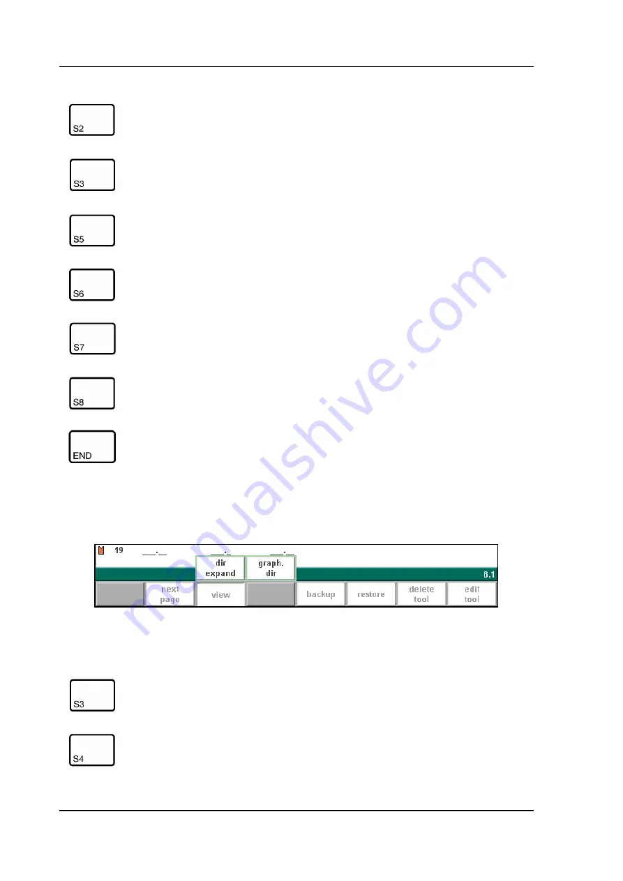
When the function key ‘View’ has been pressed a new, temporary button bar appears with 
additional softkeys:

6.k

next page

To select the next page within the several pages of the die 
library.

view

Button to select one of the possible viewing modes:
- dir. expand
- graph. dir.

backup

Save tools from library to disk.

restore

Load tools from disk into the control.

delete tool

Remove tool from library.

edit tool

To edit the tool drawing or check the die data.

To return to the program menu.

Function keys:

dir. expand

Select the normal view of the tool collection. This is the 
standard setting.

graph. dir

To get a graphical overview of the tools as available in 
the library including main dimensions of the tool.

Function keys:

Summary of Contents for DA-65W

Page 1: ...Delem Manual version V0606 DA 65W Reference Manual Operation of Version V2 ...

Page 2: ...switch in the off position the operator can only exe cute a selected program The operator cannot change the parameters to wrong unwanted val ues Version history The control software is updated regularly to increase performance and add new functionality This manual is also updated as a result of changes in the control software The following over view shows the relation between software and manual v...

Page 3: ... or insert an angle 2 6 2 3 Precision selection 2 6 2 4 Large Radius Bumping 2 8 2 5 Assignments 2 9 Parameter explanation 2 11 Parameter explanation 2 12 Parameter explanation 2 15 2 6 Bend sequence 2 16 Restoring a bend sequence 2 22 Minimum bending length 2 23 Machine Tool selection 2 24 Turn indication 2 24 Production time 2 25 Screen data 2 25 Function and control keys summary 2 26 Bend seque...

Page 4: ... 6 5 6 3 Programming of bottom dies 6 9 6 3 1 The die menu 6 9 Graphical directory dies 6 11 Edit die drawing 6 11 6 3 2 Specific die data 6 13 6 4 Machine upper side and lower side 6 16 6 5 Saving loading of tools 6 19 7 Products and tools back up 7 1 7 1 Introduction 7 1 7 2 Directory navigation 7 2 7 3 Product backup 7 3 7 4 Tool back up 7 5 8 Program Constants 8 1 8 1 Introduction 8 1 8 2 Gene...

Page 5: ...ction 9 6 9 2 Manual operation of the axes 9 7 To teach 9 8 10 Automatic step by step mode 10 1 10 1 Introduction 10 1 Parameters 10 3 Corrections 10 4 Functions screen 10 6 Graphical visualisation 10 6 Zoomed values 10 7 Bumping correction 10 8 Manual positioning 10 9 10 2 Step mode 10 10 A Parameter index A 1 ...

Page 6: ...V0606 0 6 ...

Page 7: ...n of all keys and their functions is given in the next section Beside the front panel keys a built in touchpad or external USB mouse can be used as a point ing device to select menu items parameters or softkeys It depends on your configuration whether such a device is available In this manual the phrase mouse is used to describe any of these possible pointing devices screen function keys wheel arr...

Page 8: ...sible to program all parameters of just one bending After pushing the start button all param eters are active and the backgauge will go into position It is also possible to move the axes manually Programming mode In this mode bend programs can be made or edited and also be written to or read from disk Automatic mode The selected program can be executed automatically Step by step mode The selected ...

Page 9: ...ts of the following items Keyboard decimal point clear key Clearance of the input data field in the bottom left cor ner on the monitor screen 10 numerical keys 0 9 incl alphanumeric input plus minus toggle enter key to confirm a programmed value Cursor path control Stop button Start button ...

Page 10: ...cy stop button to be implemented by machine manufacturer End of menu program It is also possible to leave a menu by pressing ESC on an external keyboard or clicking with the mouse on the menu symbol in the upper left corner On the screen pages where you find the symbol you can press the to get an explanation of the respective function or parameter to program ...

Page 11: ... can be selected in several ways enter the menu number and press ENTER use the arrow keys to scroll to the desired menu item and press ENTER click with the mouse once on the desired menu item Explanation of menu items Programming mode Select the programming mode 1 To draw your product on the screen and compute the bendsequence graphical ...

Page 12: ...ogram out of the product library 6 Write programs to or read programs from a back up medium 7 To program the dimensions of the upper tools 8 To program the dimensions of the under tools 9 To program the dimensions of the upper side of your machine 10 To program the dimensions of your machine table 11 To program specific programming data 12 Write or read tooling data and machine shapes to or from a...

Page 13: ...his help text is available when the question mark appears on the screen lower right corner 1 c To activate a help window for a parameter press the question mark key on the frontpanel or click with the mouse on the help symbol A pop up window appears with information on the active parameter ...

Page 14: ...formation as the Operation manual The help window can be used as follows Use the arrow keys up down to browse through the help text or use the function keys previ ous page and next page Press the function key end or the END key to close the Help window ...

Page 15: ... on the control have a limited number of possible values Beside such parameters the sign appears This means that the key can be pressed to get a listbox with possible values of this parameter This listbox can also be opened by clicking with the mouse on the symbol ...

Page 16: ...rizontal and vertical projected dimensions can be entered Blank length computation Real scale tool design 10 different upper side shapes and 10 different under side shapes tables Changing of lengths and angles Bumping big radius Adding or deleting of bends Existing products can be copied changed and stored as a new product Production time indication Closing dimension or highest precision tolerance...

Page 17: ...tion keys on the front panel The function depends on the type of control 2D or 3D functionality S1 thru 8 Drawing cursor control with Zoom function At bendsimulation overview in case of 2D products bendsequence menu and automatic mode Drawing cursor control for 2D products In case you are drawing the profile of your product or tools the cursor keys can be used to give directly multiples 45 degree ...

Page 18: ...rning line It will be noted on the screen if projection is not possible 1 6 Network The CNC control is equipped with a network interface The network function offers the opera tors the possibility to import product files directly from the network directories or to export the finished product files to the required network directory a 45 a 90 a 90 Horizontal projection with or key Vertical projection...

Page 19: ... control is displayed at the upper side of the menu screen in the programming mode Example of version number V 2 1 V stands for version 2 is version number 1 is version level The version number is increased when new features are added to the software the level num ber is increased when minor corrections are needed in the existing version number ...

Page 20: ...does not entitle you to any rights Delem reserves the right to change this manual without prior warning All rights reserved The copyright is held by Delem No part of this publication may be copied or reproduced without written permission from Delem BV ...

Page 21: ...a product program The maximum length is 7 digits Drawing number DN A name or description of this program The maximum length is 20 characters If an existing product number is entered a warning appears that this product already exists You are asked whether to replace that existing product with the new product or not If you choose yes the existing product is erased If you choose no you must enter a n...

Page 22: ...ode you also have the possibility to make a copy of the active product A special function key copy product appears 2 b When the function key edit notes has been pressed a new window appears in which you can edit the text about the current product See the chapter Data preparation Data Edit for more Function keys copy prod uct Copy the current product When pressed you must enter a new product number...

Page 23: ...material type The control contains 4 preprogrammed materials In total 99 materials can be programmed on the control See chapter 8 how to program materials Press the key to select the required setting Length L The Z length of the plate in millimeters mm Dimensions D1 Determine the use of the outside A or the inside B dimensions in the product drawing ...

Page 24: ...lue of the basic length of the product Then you enter the angle of the next side followed by the length of that side This procedure continues until the product has the desired profile A circle indicates the actual position With the cursor control keys you move this circle to an other position angle or length During the drawing of the profile of the product the graphical software always dis plays t...

Page 25: ...e or insert an angle depending on the drawing cursor position section 2 2 precision To define selected line segment with round cursor for high precision or if it is to be a closing dimension sec tion 2 3 bumping Bumping when the cursor is on an angle you can create an angle with a big radius section 2 4 change data To page with product data assign ments To select assignments for bending sequence c...

Page 26: ... line can be deleted 2 3 Precision selection When the drawing cursor small circle is on a line segment with S2 high precision or closing dimension can be selected With S2 these functions will be toggled giving 3 possibilities high precision closing dimension normal situation 2 f High precision At bend sequence computation the backgauge stop position will be chosen to get the highest possible preci...

Page 27: ...ssible directly placed between back stop and the centre of the die Notes Specifying line intervals with high precision and closing dimensions may result in longer pro duction time Also it will have priority over the front extend ratio if that is set to comply if possible See section 2 5 ...

Page 28: ... need a smaller V die opening to be able to bend in a proper way Which value is acceptable as maximum for the V opening of the die is calculated and displayed on the screen For the definition of the line lengths to be programmed in the part connected to a bump radius segment see figure 2 i 2 i Lengths L1 and L2 must be equal or bigger than the radius R When you must program such a bend first progr...

Page 29: ...eed with the assignments or No to go back to the edit screen See section 2 8 for more information about variants progamming Automatic bend sequence computation works with several criteria in order to find an optimum between a minimum production time handling possibilities without product machine and product tool collision In order to find one of the optimums you must program several computation pa...

Page 30: ...s which have the most opti mal values to work within your surrounding This set can be stored into the internal memory by pressing softkey S4 save as default While programming another product you can recall this previous fixed set by loading the val ues via softkey S3 save as defaults Save as default assignments settings end To go back to the drawing ...

Page 31: ...ress to the total blank length of the product You must have a minimum length of your product in front of the press to be able to handle the product Front Extend Ratio Accept FA In case programmed 0 comply if possible This means that when possible the computer tries to comply to the front extend ratio and only when this will result in no solutions to be found it will accept that the length in front...

Page 32: ...xplanation Backgauge possibilities 2 l Backstop against sharp angle allowed SA 0 if not allowed 1 if allowed Press the key to select the required setting Specify if backstop may be placed against an angle smaller than 90 2 m ...

Page 33: ... to avoid with low priority 2 if not avoidable permitted if it results that no solutions are to be found than it is per mitted 3 prohibited never allowable Press the key to select the required setting Edge tolerance ET In case backstop is against flat plate an angle tolerance is allowed deviation from hori zontal To be programmed in degrees of tolerance 0 90 input 2 o ...

Page 34: ...full in case the pressbrake has been equiped with back gaugefingers on a moving R axis having a so called lay on construction When the length of the plate at the backside of the machine is greater than this limit the X axis and R axis positions will be corrected automatically so the plate will rest on the backgauge finger 0 3200 0 mm This is only possible if an automatic R axis is enabled 2 q ...

Page 35: ...tor X axis position AF The computed inner radius is multiplied by this factor to correct the X axis position in order to have a correct product dimension after each specific bend bend allowance This factor can be checked by making a product with just one bend and a certain product dimension e g 100 mm outer dimension See figure 2 s The controller computes the X axis position necessary to obtain L ...

Page 36: ...ain a better result However it can be a problem selecting a die suitable to bend these small segments Therefore the control can calculate an equal size for all segments This can be defined with this parameter 0 disabled no equal sizes 1 enabled equal sizes Press the key to select the required setting When this parameter is set to 1 all segments will have an equal size If it is set to 0 the calcula...

Page 37: ...n the screen with S2 show library This selection will give an overview of the tools including the main properties of each tool 2 t If this overview is not sufficient to select a tool press the function key view and the key graph dir to get a graphical overview of available tools ...

Page 38: ...ch must be selected and can also be changed during the bending sequence determination These selec tions are prompted in the lower left corner of the screen Within the bend sequence screen the softkey show library will remain available to get a graphical overview of the tool library as shown above After specifying machine part and tools the product and machine will be drawn on the screen ...

Page 39: ...so possible without collision A complete overview of available softkeys in this screen is given on page 2 25 The function key more serves to switch between the primary and secondary row with function keys If the product has collision with the tools or machine it will be indicated via a warning message on the screen With these keys you can select any of the other bendings which you prefer to be the...

Page 40: ...s necessary to produce the radius are computed during postpro cessing With this function key you can switch the collision protection check on or off This is indicated at the top of the screen When you have selected collision off you can also select other bends which will give colli sion with the tools or machine parts The inner radius resulting after this bend is displayed at the top of the screen...

Page 41: ...p and cursor down key The function keys S7 and S8 enlarge or reduce the number of images that is displayed on the screen at once minimal 4 and maximal 25 During the automatic bendsequence computation you can always interrupt the computation by pressing Abort computation If the computation is interrupted the computer will give most of the times a suggestion for the bendsequence It is possibly not t...

Page 42: ...ap button or press enter Then move the cursor to the bend with which it must be swapped and press the enter key or the swap button Now the bends have been swapped If for any reason the action must be can celled press the softkey abort swap during the procedure Restoring a bend sequence A partly determined bend sequence is not automatically reset after leaving the bend sequence menu After you re en...

Page 43: ...le bending length will be calculated from the V opening parameter V but also depends on the angle to bend and the thickness of the material to be bend see figure 2 z If the programmed value for the wanted product does not correspond with the minimum possible length you will get a warning message on the screen 2 z new start new bend sequence the existing bend sequence is reset continue continue wit...

Page 44: ...r and lower part num ber It is also possible to turn the punch and die with respect to the machine shapes To achieve this the tool number must be programmed negative 2 aa In order to get a graphical overview of the available tools while you are in the bend sequence menu press the function key show library S2 If pressed an overview appears of available tools Which type of tools is shown depends on ...

Page 45: ...med in the turn time table of the assignment With automatic bend sequence computation the controller tries to find the minimum produc tion time Screen data On top of the screen some general important data is displayed Col prot on Collision and backgauge checks on or off Punch 1 Punch number selected die 1 Die number selected R in 1 3 Inner radius of the bend to be obtained with selected die Varian...

Page 46: ...m the bend number presently selected This feature gives you the unique pos sibility to fix the bending sequence interactively e g partly manual partly automatic store Automatic computation of all axes positions complete CNC program and storage in the product library of the postprocessed product more The softkeys for this mode are divided in two rows Press this key to switch from one row to another...

Page 47: ...the last bend The computation of the bend sequence starts always at the bend which is indicated with the at the lower left corner of the screen Example Product with 7 bends 2 ac In the first example the bend no 7 and no 6 are chosen manually from 5 up to 1 thereafter are show library Softkey to get a graphical overview of the tool library Zoom enlargement Zoom reducement Function keys secondary ro...

Page 48: ...ered without loss of existing corrections and bendsequence If such an existing program contains proper axis values and product positions then this informa tion can stay intact only the latest changes angle sheet length are recalculated and entered into the program For instance when a side length has been altered in the graphical bend overview and the store command is given then a question appears ...

Page 49: ... the title bar This means that the next time when a new postprocess command is started a new CNC program is built and old corrections will be lost When No S5 is chosen the action is cancelled and Variants on remains The message CNC program and corrections will be lost is not literally true The CNC pro gram is still present but it cannot be updated anymore from the graphical menu If the old CNC pro...

Page 50: ...V0606 2 30 ...

Page 51: ...o edit a program that is not currently loaded choose Product selection in the main menu In the offered list you have to select the wanted program number 4 a This page gives all data which are the same for every bending of the program main data of program For placing the cursor at one of the parameters The value entered for the selected parameter appears in the entering field situated in the lower ...

Page 52: ...rrent product 4 b After pressing the enter key the programmed value will be placed at the corresponding parameter Function keys first bend The cursor jumps to the page with the first bend informa tion edit notes Open a window with notes about the current product END Finishing the data preparation and returning to the pro gram menu ...

Page 53: ...d The required Y axis position is computed Depending on this parameter either the parameter angle or the parameter bend position will appear Press the key to select the required setting Thickness TH Thickness of the plate in millimetres Material M Selection of one of the programmed materials which are used to calculate the bending depths The control contains 4 preprogrammed materials In total 99 m...

Page 54: ...uct via menu 3 product selection 4 Go to menu 2 data editing Select the parameter CONNECT Enter the program number of the product in the other direction 5 Select the second program as in step 3 Repeat step 4 If you want to connect two pro grams as in this example you enter the program number of the first program The cycle is closed When you want to execute more than two programs in succession not ...

Page 55: ... screen the function of the softkeys in the bottom row Function keys previous bend select previous bend next bend select next bend show library Open a window with an overview of the tool library From here a tool can be selected Only available if the program cursor is positioned on a tool next page next page to select the second page of the parameters to be programmed for this bending ...

Page 56: ...ine configuration Press the END button to leave this window Axis speeds Speed of the selected axis in the current bend Speed can be programmed in a percentage of the axis func tions axis functions to change speed and retract distance of available axes in the current bend This function is machine dependant all bends to the listing of all bends of this program only possible in data editing END To en...

Page 57: ...the key to select a tool from the list Use the function key Show library to check the available tools Method BM Select the required bending method The control supports 4 methods Air bend Bottoming Flattening Flattening bottoming Press the key to select the required setting Bend methods air bend The sheet is bent to the programmed angle by bringing the punch to the required depth The control calcul...

Page 58: ... results in a certain gap opening between the punch and the die after the bend A positive value is the gap opening above Mute a negative value below Mute When you want to limit the handling time of the product you can program a small posi tive or a negative value Mute M Sequence point at which the Y axis is switched from fast closing speed to pressing speed The value programmed here is the distanc...

Page 59: ...X axis position Therefore this parameter can also be used as a chaining measure Only in case you have a configuration with a R axis The function key gauge func appears when you put the cursor bar on this X axis parameter 4 e If you press gauge func a window appears with three programmable parameters 4 f Gauge pos GP With this function you can program another gauge position for this specific bend T...

Page 60: ...nger position X Default value the value in X direction of the gauge position for the plate This value can manually be adjusted in this window if required With END you leave the window and the new values have been saved If you press cancel you leave the window without changes When you have changed the Gauge position then the axes positions in X and R direc tion have also been changed Therefore the ...

Page 61: ... mute position when the beam moves in the opening direction with the Y axis beam waiting at the pinching point until the backgauge is at the retract posi tion 12 Step change at upper dead point with the Y axis beam waiting at the pinching point until the backgauge is at the retract position 13 Step change at upper dead point without movement of any axis The Y axis beam will wait at the sheet clamp...

Page 62: ... during pressing auto calculated Dwell time T Holding time of punch at bending point Decomp speed BS The decompression speed is the programmable speed which is active during the pro grammed decompression stroke Decompression DC Decompression stroke after bending to release the working pressure Parallelism Y2 Difference of left and right hand side cylinder Y1 and Y2 When positive right hand side lo...

Page 63: ... all bends in the bumping sequence should have the same angle number but a different bumping number Programming a radius bend in this manner will allow for bumping correction in the production mode 4 j Backgauge number XN A backgauge number refers to a certain spot of the product that can be placed against the backgauge during bending Such a spot is either a product end or an angle The back gauge ...

Page 64: ...he product in a production mode Automatic mode or Step mode This visualisation does not require a product drawing only these parameters must be programmed correctly Furthermore the parameter Blank Length must be programmed correctly in order to obtain a visualisation Note After selecting a new bend this will be a copy of the preceding one you only have to program those parameters which are differe...

Page 65: ...Delem V0606 4 15 Example Product to make 4 l 0 to 5 are possible backgauge positions 1 to 4 are angle numbers 4 m Bend Angle AN Backgauge XN 1 1 0 2 4 5 3 3 1 4 2 1 ...

Page 66: ... the required axis The softkey show slaves S7 will appear After pressing this key a new pop up window appears in which the values of the axis and its slaves are shown 4 n Each slave can be programmed with a different value If no values are programmed the slaves will follow the master Furthermore the same minimum and maximum values apply for the slaves as for the master axis This pop up window is a...

Page 67: ... a complete overview of the bend ings programmed After pushing END the page will be restored from which this page was selected with the cursor on the parameter selected before 4 o A specific bend can be selected on the screen by putting the highlighted bar on that bend then pressing END The view is split in two parts At the top of the parameter screen the general parameters of the product are show...

Page 68: ...insert a new bend between one of the bends select with the cursor keys first the bend after which a bend must be inserted Then push S1 for inserting results in a new bend which is a copy of the previous one delete bend To delete a bend of the program first select this bend with the cursor highlighted bar mark bend Mark the current bend in order to prepare it for another action like move or swap Se...

Page 69: ...e A bend is no longer marked when the mark is aborted when an action is finished or when this menu is left Ending data preparation data editing After pushing the END key in the Data edit screen a new page with product number and draw ing number appears 4 p At this page the program number and the drawing number must be given to the new prepared program or can be changed in the edit mode If either w...

Page 70: ...Decompression 3 Crowning device setting 4 Z axis position offset 5 X axis position correction Parameters 1 through 4 are only automatically recalculated if the parameter Auto computa tions edit see the menu program constants has been activated value 1 Parameter 5 is only automatically recalculated if the parameter Bend allowance see the menu program constants has been activated value 1 Additional ...

Page 71: ...gram from the mainmemory The loaded product can directly be exe cuted in the automatic mode Each item in the list consists of a symbol and a number The number is simply the product number the symbol can have the following meanings the product has a CNC program there is no drawing red the product consists of a 2D drawing there is no CNC program green the product has a 2D drawing and a CNC program r...

Page 72: ...h dir filter Function key to open a new button bar with extra function keys for product selection functions prod nr draw nr search local direc tory Via local directory you get an overview of the manually created product directory structure delete Delete programs from the memory End the product selection Function keys normal dir Select a normal view of the product collection This is the standard se...

Page 73: ... tional softkeys 5 c graph dir Select a graphical overview of the product collection Function keys prod nr Products are shown in columns with symbols and product number they are sorted on product number This is the default view draw nr If this key is pressed in this screen the list of products is automatically sorted on the alphabetical order of drawing numbers search Start the search function to ...

Page 74: ...is selected you can search for products with a certain number or name At the bottom of the screen the text search to load is displayed to indicate that you may enter a string the control will search for You can either enter a complete name or number or only a part of it Press enter to start a search If you enter part of a name and this part occurs in several product names the control will show all...

Page 75: ...Delem V0606 5 5 5 e ...

Page 76: ...r Add a new subdirectory The name of the subdirectory can be any alpha numeric string of maximal 8 characters Avoid the use of slashes remove sub dir Delete a subdirectory If the subdirectory is not empty the control returns the message UNABLE TO REMOVE DIRECTORY An empty subdirectory is deleted without warning The default directory PRODUCTS can also be deleted When all the subdirectories have bee...

Page 77: ...ter the new name Subdirectories are called subdirectories because these directories reside under the local directory PRODUCTS 5 g It is not possible to copy products from one subdirectory to another subdirectory A product must be restored in a subdirectory via the menu product backup You cannot change the name of the subdirectory When you leave the product selection menu the control remembers the ...

Page 78: ...V0606 5 8 ...

Page 79: ...ches 6 2 1 The punch menu The programming of punches is started by choosing Punches in the main menu The punch profile can be created with help of the programming facilities of the control 6 a A listing of punches programmed into the memory is given The punch is selected by moving the highlighted cursor bar resulting in the drawing of the upper tool ...

Page 80: ...ect the next page within the several pages of the punch library view Button to select one of the possible viewing modes dir expand graph dir graph heel dir backup Save tools from library to disk restore Load tools from disk into the control delete tool Remove tool from library edit tool To edit the tool drawing or edit the punch data Function keys dir expand Select the normal view of the tool coll...

Page 81: ...ted here until one of these three function keys has been chosen The temporary bar will disappear again Graphical directory 6 c graph dir To get a graphical overview of the tools as available in the library including main dimensions of the tool Function keys ...

Page 82: ...of the tool Important this height value will be used in bend depth calcula tion Angle a The angle of the punch tip Hereafter you can enter angle and length dimensions as in the product drawing facilities 6 d Function keys auto finish Finishing the tool outline to the top of the tool automati cally change height To change the height dimension of the tool ...

Page 83: ...tom point of the punch will be placed on the center line of the press brake shape 6 2 2 Specific Punch Data 6 e delete line To delete a line segment delete drawing To delete the complete tool from the library change data To change specific tool data and code see section 6 2 2 To return to the directory overview Function keys ...

Page 84: ...ection criterium the value will not be used in compu tation formulas Flattening height FH The flattening height need to be programmed when you make use of a special flattening punch to flatten your product The programmable height is used to calculate the Y axis value in case of flattening The default value for this parameter is the standard tool height which is already programmed Every time that t...

Page 85: ...unches Such punches could cause inaccuracies in the tool height and the resulting Y axis position The control makes a distinction between two settings head mounted and shoulder mounted 0 shoulder mounted default setting 1 head mounted Press the key to select the required setting 6 h If shoulder mounted is chosen the Y axis position is calculated from the standard tool height This is the default se...

Page 86: ...V0606 6 8 6 i ...

Page 87: ...mming of dies is started by choosing Bottom dies in the main menu 6 j A listing of the programmed dies is given A die can be selected with the highlighted cursor Function keys previous page To select a previous page within the several pages of the available dies in the library ...

Page 88: ... expand graph dir backup Save tools from library to disk restore Load tools from disk into the control delete tool Remove tool from library edit tool To edit the tool drawing or check the die data To return to the program menu Function keys dir expand Select the normal view of the tool collection This is the standard setting graph dir To get a graphical overview of the tools as available in the li...

Page 89: ...ar again Graphical directory dies 6 l Edit die drawing When starting the die drawing the display prompts the main dimensions of the die Height H The height of the tool Important this height value will be used in bend depth calcula tion V opening W The V opening of the die Angle α The angle of the die Radius RA The radius of the edges of the V opening ...

Page 90: ...ide of the die is the backgauge position The mid position of the V opening will be placed on the centre line of the press brake shape 6 n The length of the flat section on the right hand side of the V grove will be used in order to cal culate the minimum X axis position for the R axis collision detection with die X safe Function keys The softkey functions are exactly the same as for punch programm...

Page 91: ... FS V in which FS flat section on the right hand side of the V grove V opening value In this formula also an extra small safety value has been added X safe turned negative ST This second safety value will be active if the die is used in the turned position This can be achieved by programming the die in the bendsequence computation with a negative number For instance Program for die number 2 2 if y...

Page 92: ... the speed change point mute and the flattening height will be used to calculate the end position of the Y axis beam to flatten the product The calculation will take 2x sheet thickness into account Also you can program a flat tening offset in the menu Program constants This value will be added to the value of 2x sheet thickness 2nd x safe SN 2nd x safe turned negative ST Second automatically calcu...

Page 93: ...hese values are calculated each time the die drawing changes These 2nd values cannot be changed manually 6 r H2 is the height of the 2nd values H2 is not visible on the screen See for explanation upon the safety zones the example drawing ...

Page 94: ...ry button bar appears with Function keys view Button to select one out of two possible viewing modes dir expand graph dir backup Save tools from library to disk restore Load tools from disk into the control delete tool Remove tool from library edit tool To edit the machine shape drawing or check the dimen sions ...

Page 95: ...hine Before starting drawing the machine shape upper or lower side you must enter the press beam height of the upper part when the moving part of the upper side is in its mechanical top dead centre The length prompted after entering the height of the machine shape is the distance from the center line to the front side or the back side of the machine Function keys dir expand Select the normal view ...

Page 96: ...V0606 6 18 6 u For the lower side of the machine the height is defined from the table surface to the floor level 6 v ...

Page 97: ...ck up location floppy disk network When the function key backup has been pressed a screen like shown below should appear 6 w At the top of the screen the back up location is shown If this location is not correct you can change the subdirectory with the softkey backup directory To save a tool enter its number from the list and press enter Function keys all Save all tools backup directory Change mak...

Page 98: ... or delete existing ones with the softkeys make subdir and remove subdir If there are subdirectories present use the arrow keys to scroll to the required directory and presss enter to select it view Button to select one out of two possible viewing modes normal dir dir expand graph dir Function keys make sub dir Add a new subdirectory The name of the subdirectory can be any alpha numeric string of ...

Page 99: ... on the disk is first renamed before it is loaded from disk This means in case of rename that a new toolnumber is proposed This new toolnumber is the first free tool number in the tool library Accept the proposed tool number with the enter key or enter the number of another free tool number and press the enter key 6 y Note Tools are linked to the control by their machine number When a restore oper...

Page 100: ...V0606 6 22 ...

Page 101: ...ding data are similar for all types of back up media floppy disk network or USB disk The actual back up directory consists of a device USB disk network and a directory The choice of devices depends on which devices are connected to the control If necessary directo ries can be created and selected The back up locations for storage of products and tools are set independently 7 a ...

Page 102: ...number of times until the highest level is reached From there select the proper device and choose the correct subdirectory If a network connection is available you must first select network and subsequently one of the offered network volumes After that it works similar to other devices You can make new subdirectories or delete existing ones with the softkeys make subdir and remove subdir If there ...

Page 103: ...able It is also indicated to which loca tion a backup is made floppy disk network etc remove subdir Delete a subdirectory If the subdirectory is not empty the controller returns the message UNABLE TO REMOVE DIRECTORY Function keys backup products Open the back up menu to save products to disk restore products Open the restore menu to load products from disk Function keys ...

Page 104: ...tkey backup directory or you should go to the program constants menu to change the device where products are saved to To save a product enter its number from the list and press enter Function keys all load all products backup direc tory Change make or remove backup directory draw nr Toggle drawing number product number local direc tory get an overview of the manually created product directory stru...

Page 105: ...on 7 4 Tool back up To make a back up of tools to disk choose Tool backup in the main menu 7 e With this menu a back up of all programmed tools on the control is made punches dies and machine shapes When activated one warning is given that existing tools with the same num ber on the destination disk will be replaced view Button to select one out of two possible viewing modes normal dir dir expand ...

Page 106: ... are imported Tools are linked to the control by their machine number When a restore operation is started the control will only import those tools which have the same machine number as the control If for any reason the machine number is changed a new tool back up operation should be exe cuted to save the control tools with their new machine number If this has not been done the control will detect ...

Page 107: ...eneral 8 a Use the keys next page S2 and previous page S1 to browse through the various pages with parameters Use the arrow keys up down to select individual parameters Inch mm select IS 1 dimensions in inches 0 dimensions in millimeters Press the key to select the required setting Ton kN select TS 1 Ton 0 kN It is possible to select the units for all Force data to be expressed in Tons or kN Press...

Page 108: ...configuration which languages are available Press the key to select the required setting 0 English 11 Polish 1 German 12 Lithuanian 2 Danish 13 Slowenian 3 French 14 Turkish 4 Italian 15 Russian 5 Dutch 16 Brazilian 6 Swedish 17 Hungarian 7 Czech 21 Chinese 8 Spanish 22 Chinese Traditional 9 Finnish 23 Korean 10 Portugese 24 Japanese ...

Page 109: ...he Help function is available in the following languages 0 English 1 German 2 Danish 3 French 4 Italian 5 Dutch 6 Swedish 7 Czech 8 Spanish 9 Finnish When the cursor is on the parameter Help language the function key add help language appears With this function key you can install a new help language on the control Make sure the required help file is present on the control disk or another accessib...

Page 110: ...ontrol For each material three properties are present and can be viewed and edited Material name NA Name of the material The maximum allowed length of the material name is 25 charac ters the name must begin with a character not a numeral Tensile strength S Tensile stength of the selected material E module E E module of the selected material Function keys edit name To change the name of the current...

Page 111: ...ursor to the relevant line and press the function key delete material S6 to erase the values To program a new material move the cursor to an empty space and start programming its val ues 8 4 Program settings 8 e Machine number MN When there are several bending machines in a factory it can be useful to give the control on each machine a unique machine number The selected machine number will be stor...

Page 112: ...resent in the database If corrections for certain bends are available then they will be offered On other occasions corrections can be interpolated and offered The correction database is adjusted by entering new corrections during production When the database is enabled with this parameter all new entered corrections are stored in the database When searching for similar bends the control searches f...

Page 113: ...erence programming XX 0 angular format 1 projection method When you have two independent X axes X1 and X2 and the option OP X1X2 has been installed you can program the values for X1 X2 in a certain relation This means that you program X1 and an angle value angular method or in a projection measure Please ask the option description from your supplier when this option has been installed Only availab...

Page 114: ...chosen the name of that table if it has a name is shown on the screen Press the key to select the required setting Data preparation bend allowance BA 0 correction off 1 correction on With this parameter you can choose whether or not you wish to have programmed values corrected for bend allowance This on off setting only refers to corrections during prod uct programming in the menu data preparation...

Page 115: ... in a new window with its own set of function keys 8 g Each line contains a table entry with several parameters In this screen the following function keys are available Use the arrow keys to scroll to the field you wish to change Then type the new value and press ENTER It is not possible to create a table through this menu Only when a table has been loaded into the control is it possible to edit i...

Page 116: ...xis beam in case of flattening your product depends on the programmed flatten height of your special tool and the sheet thickness x2 and the here programmed offset to realise a flattened product as you require Z distance ZD When automatic Z axes are installed the distance of the fingers on the backgauge are automatically calculated with respect to the end of the plate 8 h 8 6 Production settings 8...

Page 117: ...ng parameters active will take place To perform the next bending you must select the new bending and press the start button When programmed 1 The next bending parameters are loaded automatically but the axes will start positioning after the start button has been pressed Parallelism offset PO An overal parallelism valid for the complete Y axis stroke can be programmed with this parameter The progra...

Page 118: ...or the X2 axis Part support retour speed PR Return speed of the part support after a bending The speed value is programmed as a percentage of the maximum speed Only available when there is a part support on the system Part support extra angle PE Extra angle for the part support unit This angle value is added to the part support angle position at the end of decompression So while the pressbeam move...

Page 119: ...Z movement is started when X axis is outside the zone Old X axis position as well as new position inside the zone backgauge moves to the intermediate X axis position then the Z movement is started When the Z axes are in position the X movement is started to move the backgauge to its new position see figure 8 j Intermediate R for X movement RS Temporary position for the R axis to avoid collision as...

Page 120: ...al ports To change these settings contact your machine supplier The following settings are available DNC The serial port is used for DNC operation which means the control can be accessed by a computer through a serial connection according to RS 232 Other settings are machine dependent If a serial port is already programmed to another setting it is not available for DNC anymore ...

Page 121: ...lative small product which is long in x direction needs some longer time to turn from front to back or in a combination turn The turn time can be set in a table in seconds For this purpose there are 4 length intervals 3 boundaries each with a specific turn time depending on the type of turn Like the turn times you also can set the length limit boundaries Closing speed CS Speed of the Y axis during...

Page 122: ...com puted 8 o Gauge positions GN The number of possible gauge positions max 4 When this parameter is changed a new pop up window with finger geometry appears There the finger dimensions can be pro grammed Default lay on position GD Default gauge lay on position when lay on is selected during the graphical bendsequence programming Default value 0 not lay on Gauge R offset RO An offset value for the...

Page 123: ...ative value gives a lower backgauge position This offset is only valid for gauge position 0 Finger width FW The width of the backgauge finger 8 q When the function key edit drawing has been pressed a new window appears wherein the dimensions of the backgauge finger can be programmed 8 r ...

Page 124: ... to the number of gauge positions Finger height FH The height or thickness of the first backgauge finger tip Gauge height H1 H2 H3 H4 The height of the different finger levels Finger length FL The length of the first finger Gauge length L2 L3 The length of additional lay on levels 8 10 Part support dimensions If a part support is installed this page can be used to program the size and place of the...

Page 125: ...own above Part support unit 1 2 3 4 5 P1 2 3 4 5 With these parameters the positions of the part support units can be programmed Possi ble settings are ABSENT part support is not present or is switched off FRONT LEFT BACK LEFT FRONT RIGHT BACK RIGHT A maximum of 5 part support units can be programmed The number of part support units that actually appears on this page is machine dependent ...

Page 126: ...parameters on this page 8 u Event logging EL To switch the event logging function on or off Filename EF The name for the log file Enter the required name the extension txt will be added to the filename automatically Path EP The folder directory where the log file will be stored This path can be on the internal memory of the DA control Hard disk a USB memory stick or even a network drive if connect...

Page 127: ... parameters should be switched on for logging Controller start SA Log event the control has been started Controller stop SO Log event the control has been stopped Step change SC Log event the control has switched to the next bend step Product complete PC Log event the last step of a bend program has been finished Mode change MC Log event a different mode has been selected Error message EM Log even...

Page 128: ... with a few possible attributes The time is always listed followed by the nature of the event The time is listed as follows time date T time The date is shown in the order year month date the time is shown in the order hours minutes seconds These two fields are separated by the T character The nature of the event is indicated by a keyword Depending on its nature one or more attributes are listed ...

Page 129: ...location to store the file The maximum file size supported by the control is 1 Megabyte 1000 Kilobytes Event type Keyword Possible attributes Mode change mode mode number 1 manual 2 programming 3 automatic 4 step by step Step change step product number step number Control start start product number step number and stock counter Control stop stop product number step number and stock counter Product...

Page 130: ...V0606 8 24 8 12 Maintenance 8 w Hours The number of hours the machine is running Strokes The number of strokes the pressbeam has executed ...

Page 131: ...ibration 9 a All the parameters can be programmed independently of the programs in memory Manual mode By pushing this key the CNC is in manual mode Function keys view Button to select one out of three possible viewing modes axes aux axes zoomed values show library Open a window with an overview of the tool library From there a tool can be selected ...

Page 132: ...in the chapter Data preparation manual pos Start the function to move axes manually with the hand wheel See section 9 2 Function keys axes Switch to default parameter view aux axes Switch to second view with parameters of auxiliary axes zoomed values Switch to view with axes values axis state Switch to view with state of the available axes Available for service purposes IO status Switch to view wi...

Page 133: ...hickness TH Thickness of the plate in millimeters Length BL Length of the plate between the tools in millimeters Method BM Select the required bending method The control supports 4 methods Air bend Bottoming Flattening Flattening bottoming Press the key to select the required setting See chapter 4 for more information about possible bend methods Corr α Cα Correction on angle to bend The angle corr...

Page 134: ...he plate Auxiliary axis R If you have one or more auxiliary axes for instance a R axis Z axis or part support the parameters of these axes appear here When you have a R1 axis and a R2 axis the pro grammed R1 value is automatically copied to the R2 axis value The R2 axis value can if necessary be changed afterwards Open DY This parameter results in a certain gap opening between the punch and the di...

Page 135: ... a general correction on the angle position of the part support It is valid for all bends The correction is programmed here as an angle value relative to the part support angle of the current bend The correction is remembered as a percentage of the current angle If another bend is programmed or selected with a different angle the correction value will be adjusted accordingly Only available if a pa...

Page 136: ...V0606 9 6 Zoom function When the function key zoomed values has been pressed the control switches to a new view with only axes values on the screen 9 d ...

Page 137: ...s you wish to move Auxiliary axes With the handwheel the backgauge can be positioned manually This operation is only possible in Stop Manual Mode First you select the respective backgauge axis with help of the Manual positioning key so that you will see the cursor bar at the required axis Then you can move the axis with help of the wheel Y axis With the handwheel the punch can be positioned manual...

Page 138: ...n teach an axis a correct position within the manual positioning mode When you have moved an axis to a certain position with the handwheel you may want to store this position To do so press the ENTER key within this screen The actual axis value left side will appear in the programmed axis field right side ...

Page 139: ...his is also indicated with a check tools warning message when you enter the automatic mode In the header information is displayed on the number of bends the repetition of a bend the product number the drawing number and the connected program the latter two do not have to be present Above the horizontal line the programmed and computed parameters are displayed These parameters are divided over two ...

Page 140: ...dditional functions select rept no Switch between display of bend number or the number of repetitions of this bend all corr Open window to edit corrections of all bends of the product See section about corrections manual pos Start function to move an axis manually with the hand wheel and change the axis positions with the teach func tion like in manual mode Function keys axes Switch to default vie...

Page 141: ... been entered the resulting corrections for Y axis and parallellism are calculated The corrections will be saved in the active bending program The angle correction should be entered as following examples indicate 1 Programmed value of 90 degrees Measured value of 92 degrees Then it is required to program Corr α with 2 2 Programmed value of 90 degrees Measured value of 88 degrees Then it is require...

Page 142: ... of 202 millimeters Then it is required to program Corr x with 2 2 Programmed value of 200 millimeters Measured value of 198 millimeters Then it is required to program Corr x with 2 Stock ST The stock counter is incremented or decremented after each end of a program cycle G Corr α Gα General correction of the angle valid for each bend of the program The value should be programmed in the same manne...

Page 143: ...e a necessary correction to reach the programmed angle If there is already a correction present the control will adjust this correction to account for the latest discrepancy The column Stored correction is only available when the Angle correction database has been activated When activated the column Stored correction shows for each bend the correction value that is present in the database A blank ...

Page 144: ...V0606 10 6 Functions screen 10 d Graphical visualisation 10 e ...

Page 145: ...Delem V0606 10 7 Zoomed values 10 f ...

Page 146: ...h the correction can be entered 10 g When the general correction of an angle is altered all individual corrections are recalculated When any of the individual corrections is altered the general correction is recalculated Bumping corrections can be programmed independently for both sides α1 and α2 When the general correction α1 is changed it is automatically copied to α2 and as a result all separat...

Page 147: ...0606 10 9 Manual positioning In the automatic production mode it is possible to move the selected axis manually with the handwheel and change the axis positions with the teach function like in manual mode 10 h ...

Page 148: ... pressing start on the front panel of the control 10 i After each bending step the control can stay in the current bend or jump to the next bend This depends on a parameter in the programming constants 10 j Disabled when a step is completed the control will stop and stay in the current step Enabled when a step is completed the control will load the next step and stop See also the chapter about pro...

Page 149: ...mpression 9 4 Default lay on position 8 16 Default X time 8 7 Default X axis code 8 7 Delay time 4 11 Die 4 7 Die 9 3 Dimensions 2 3 Drawing number 2 1 D time 9 5 Dwell time 4 12 E module 8 4 Edge tolerance 2 13 Equal sized bumping segments enabled 2 16 Error message 8 21 Event logging 8 20 Filename 8 20 Finger height 8 18 Finger length 8 18 Finger width 8 17 Flattening height 6 14 Flattening heig...

Page 150: ...gth 2 15 Radius factor X axis position 2 15 Repetition 10 3 Repetition 4 12 Resistance 6 13 Resistance 6 6 Retract 4 10 Retract 9 4 R finger position 4 10 Serial port 1 2 8 14 Speed 4 12 Speed 9 4 Step change 8 21 Stock 10 4 Stock count mode 8 11 Strokes 8 24 Support type 6 7 Tensile strength 8 4 Thickness 2 3 Thickness 4 3 Thickness 9 3 Ton kN select 8 1 V opening 6 11 X axis speed 8 15 X1X2 diff...

Reviews: