background image

19

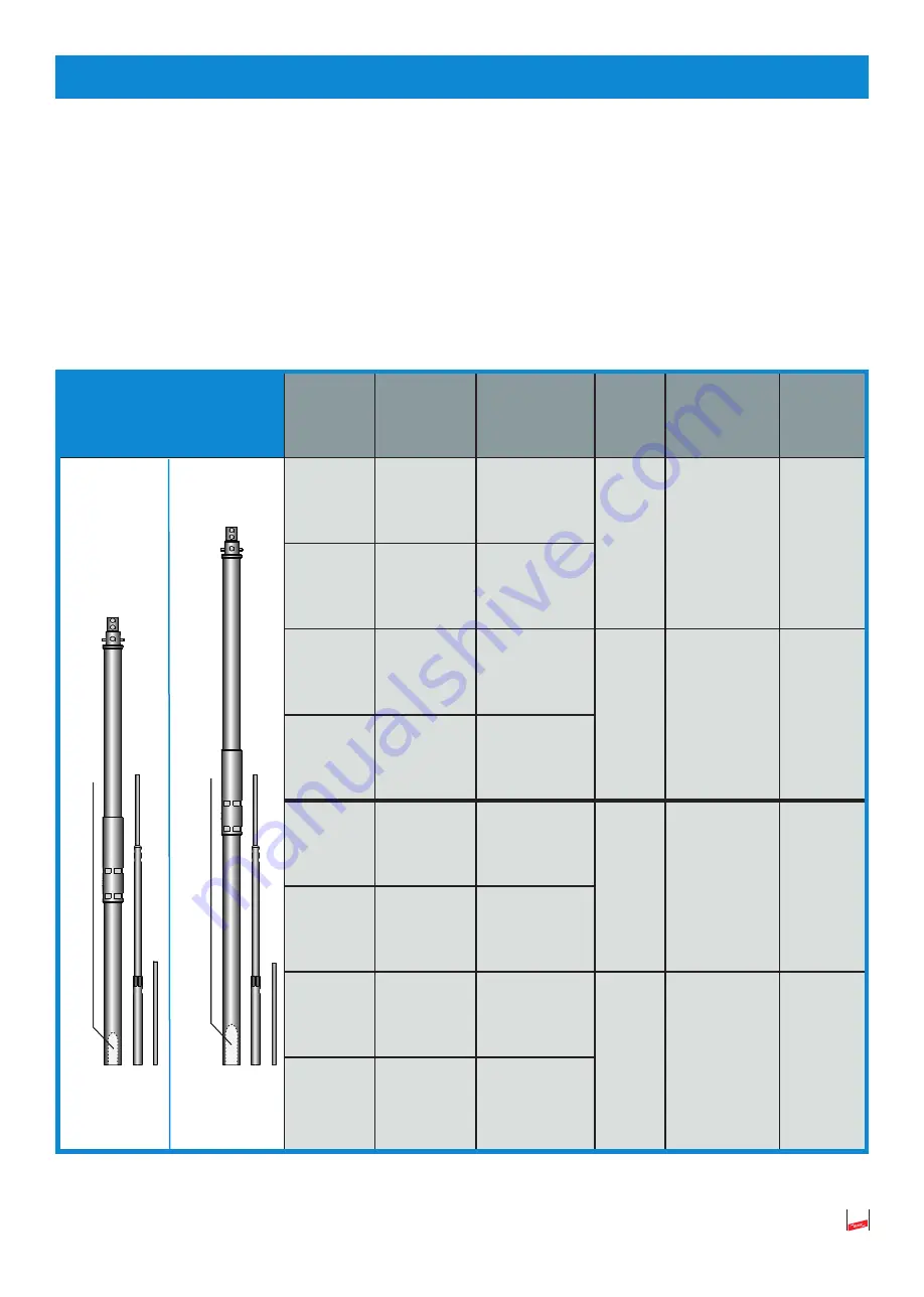
4.4  Stützrohre mit Fangspitze / Fangstange

Bei  den  verwendeten  Stützrohren  für  die  Innenverlegung  der 

HVI  long


Leitung

  ist  ein  PA-

Federelement für den Endverschluss integriert. Bei der Ausführung mit Fangspitze (Ø 10 mm) ist der 
benötigte 

Adapter bereits im Stützrohrkopf vormontiert. Der Stützrohrkopf ist in sich mechanisch 

geschlossen und daher wasserundurchlässig.

Art.-Nr.

Werkstoff

Montageset 

gebündelt, 

bestehend 

aus:

Bau-

teil-

länge

Fangspitze/ 

-stange

Gesamt-

länge

105 330
105 314

GFK/Al
GFK/NIRO

Stützrohr

3,2 m

Ø 10 mm

Länge 1,00 m

4,2 m

105 325
105 336

GFK/Al
GFK/NIRO

Stützrohr mit 
seitlichem Aus-
lass

105 331
105 315

GFK/Al
GFK/NIRO

Stützrohr

3,2 m

Ø 22/16/10 mm

Länge 2,5 m

5,7 m

105 326
105 337

GFK/Al
GFK/NIRO

Stützrohr mit 
seitlichem Aus-
lass

105 332
105 316

GFK/Al
GFK/NIRO

Stützrohr

4,7 m

Ø 10 mm

Länge 1,00 m

5,7 m

105 327
105 338

GFK/Al
GFK/NIRO

Stützrohr mit 
seitlichem Aus-
lass

105 333
105 317

GFK/Al
GFK/NIRO

Stützrohr

4,7 m

Ø 22/16/10 mm

Länge 2,5 m

7,2 m

105 328
105 339

GFK/Al
GFK/NIRO

Stützrohr mit 
seitlichem Aus-
lass

Tabelle 9 

Stützrohre

optional mit seitlichem 

Auslass

optional mit seitlichem 

Auslass

Summary of Contents for HVI power

Page 1: ...www www dehn de Publication No 1841 Update 07 19 Mat No 3003899 Copyright 2019 DEHN SE Co KG DE Blitzschutz Erdung Montageanleitung HVI Leitung HVI Leitung vorkonfektioniert HVI long Leitung ...

Page 2: ...Leitung 15 4 Konfektionierung Vorkonfektionierung der HVI Leitung 16 4 1 Montage von Kopfstück bzw Anschlusselement 16 4 2 Umschrumpfen 17 4 3 Absetzen des grauen Mantels für die Verlegung im Stützrohr 18 4 4 Stützrohre mit Fangspitze Fangstange 19 5 Montage 20 5 1 Montage der HVI long Leitung im Stützrohr 20 5 2 Maßnahmen zur Verringerung des Trennungsabstandes s außen geführten HVI Leitungen 22 ...

Page 3: ...r Länge 3 2 m errichtet im Dreibeinstativ 34 8 Leitungsverlegung 36 8 1 Zusätzlicher Anschluss des äußeren Kabelmantels zum Zwecke des Potentialausgleiches 36 8 2 Windbeanspruchung Windlast 37 9 Checkliste für HVI Installation 39 ...

Page 4: ... der HVI Leitungen müssen bei entsprechenden Anwendungen die Sicherheitsvor kehrungen gegen Brand und Explosionsgefahren berücksichtigt werden  Soll die HVI Leitung auf weich gedeckten Dächern z B Reet Stroh eingesetzt werden sind für die se feuergefährdeten Betriebsstätten besondere Montagebedingungen einzuhalten Die besonderen Montagebedingungen sind für die HVI Leitung im EB Hauptkatalog Blitz...

Page 5: ...tel in Farben und Lacken verdunsten bei einem kurzzeitigen dünnen Auftrag schnell und führen nicht zu einer Beschädigung des Kunststoffes   Für die Anwendung in explosionsgefährdeten Betriebsstätten sind besondere Montagebedingungen zu beachten siehe Mon ta gean lei tung Publication No 1501  Die HVI Leitung ist ein Bauteil zur Einhaltung des Trennungsabstandes Konstruktionsbedingt be sitzt dies...

Page 6: ...hutz Teil 3 Abschnitt 6 3 erläutert mit dem Materialfaktor km 1 für Luft oder km 0 5 für festen Baustoff durchzuführen Es muss geprüft werden ob dieser errechnete Trennungsabstand mit dem äquivalenten Trennungsabstand der HVI Leitung siehe technische Daten Tabelle 1 Seite 7 realisiert werden kann errechneter Trennungsabstand äquivalenter Trennungsabstand Ist dies nicht der Fall dann sind die im Ka...

Page 7: ...emperaturbereich bei fester Verlegung 30 bis 70 C Umgebungstemperatur und Leitungstemperatur bei Verlegung und Verarbeitung 5 bis 40 C max Zugbelastung 950 N Innenleiter Kupfer mehr eindrähtig 19 mm Tabelle 1 Technische Daten HVI Leitung 2 3 Chemische Eigenschaften schwarz RAL 9011 grau RAL 7035 Brandverhalten selbstverlöschend Nein Ja Witterungsbeständig UV stabilisiert Ja Brandlast 3 6 kWh m 4 3...

Page 8: ...nn auf Grund der auftragsbezogenen Fertigung Konfektionierung der Leitungslänge die Leitung nicht zurückgenommen werden Die vorkonfektionierte HVI Leitung ist in einer Standard Mindestlänge von 6 m verfügbar und kann mit 0 5 m Schritten erhöht werden Die Standardmindestlänge von 6 m ist für den Einsatz in Kombination mit dem 3 2 m langen Stützrohr ausgelegt Es wird lose beiliegend ein Anschlussele...

Page 9: ... 819 227 schwarz grau Außen Einsatzbereich Wird verwendet wenn die Fangeinrichtung des Äußeren Blitzschutzes direkt mit der Erdungsanlage verbunden wird Tabelle 3 HVI Leitung werkseitig vorkonfektioniert z B HVI Leitung schwarz Übersicht HVI Leitung mit Spezialmantel Kopfstück montiert Lose beigelegt sind Anschlusselement Schrumpfschlauch Innensechskantschlüssel Kopfstück und HVI Leitung umschrump...

Page 10: ...229 PA Anschlusselement 105 275 Abstandshalter mit PA Element Einsatzbereich Wird eingesetzt wenn z B mehrere zu schützende Anlagenteile nicht einzeln sondern gemeinsam über eine Getrennte Ringleitung mit der Erdungsanlage des Gebäudes ver bunden werden siehe Bild 17 auf Seite 28 Die Leitung mit einem im Stützrohr ange brachten Endverschluss und einem vor Ort zu erstellenden Endverschluss wird typ...

Page 11: ... Montageanleitung Zur Konfektionierung vor Ort 819 131 schwarz RAL 9011 6 70 m Abgelängt nach Kundenvorgabe verpackt 819 136 grau RAL 7035 100 m Einwegtrommel Außendurchmesser ca 800 mm Trommel Breite ca 485 mm incl 1 Innensechskantschlüssel und Montageanleitung Zur Konfektionierung vor Ort 819 132 grau RAL 7035 6 70 m Abgelängt nach Kundenvorgabe verpackt Tabelle 5 Lieferumfang HVI long Leitung ...

Page 12: ... außen am Stützrohr Kopfstück für Anschlussplatte und Anschlusselement für andere Teile des Äuße ren Blitzschutzes oder der Erdungsanlage inkl 2 Schrumpfschläuche schwarz und 4 Kabelbinder 819 148 Anschlussset grau Kopfstück und Anschlusselemente zum Anschlie ßen der HVI long Leitung an beiden Enden beim Erstellen des Endverschlusses der Leitung außen am Stützrohr Kopfstück für Anschlussplatte und...

Page 13: ...ßen der HVI long Leitung beim Erstellen des Endverschlusses der Leitung außen am Stützrohr inkl 2 Schrumpfschläuche schwarz grau Kopfstück für Anschlussplatte Gewinde M12 819 199 Anschlusselement schwarz Anschlusselement zum Anschließen der HVI long Leitung beim Erstellen des Endverschlusses der Leitung inkl 1 Schumpfschlauch schwarz Bolzen D10 L 50 mm 819 198 Anschlusselement grau Anschlusselemen...

Page 14: ...der HVI Leitung mit MV Klemme für den Anschluss Rd 16 mm Rd 8 10 mm 597 220 HVI strip 20 Abisolierwerkzeug für ein mehrdrähtige Leitungen 597 032 HVI cutter Kabelschere zum Ablängen der HVI Leitung 597 230 DEHNhelix Werkzeug zum Abmanteln des zusätzlichen grauen Mantels der HVI Leitung Tabelle 7 Anschlusselemente HVI long Leitung Einzelteile Anmerkung Das vollständige Bauteileprogramm kann aus dem...

Page 15: ...andmontage mit Langloch NIRO Ø 20 23 mm Langloch Ø 5 5 x 10 mm 275 259 Leitungshalter HVI Leitung Leitungshalter für Wandmontage mit Kunststoffsockel NIRO Ø 20 23 mm 202 829 Dachleitungshalter Dachleitungshalter mit vorgeformten Biegestellen zum Verlegen der HVI Leitung auf Steildächern NIRO Ø 20 23 mm 253 229 Flachdachhalter SET Zum Verlegen der Leitung auf Flachdächern Gewicht 4 6 kg 253 239 Fla...

Page 16: ...iert bzw vorkonfektioniert Die nachfolgenden Montageschritte sind dabei zu beachten siehe auch Bild 2 Â Kopfstück bzw das Anschlusselement an die HVI Leitung heranführen und mit Rechtsdrehung auf das jeweilige Leitungsende bis zum Anschlag aufdrehen Unterstützend kann dazu auch ein Gabel schlüssel Schlüsselweite SW 19 an der Schlüsselfläche des Kopfstückes bzw dem Anschlussele ment angesetzt werde...

Page 17: ...müssen bündig mit dem Umschrumpfungsbereich abschließen Gegebenenfalls müssen sie während der Um schrumpfung nachpositioniert werden  Die vorgegebene Schrumpftemperatur von max 150 C ist einzuhalten  Im Umschrumpfungsbereich der HVI Leitung dürfen keine zu hohen Schrumpftemperaturen ange wendet werden Bei überhöhter Schrumpftemperatur kann der halbleitende Mantel der HVI Leitung beeinträchtigt o...

Page 18: ...597 230 Die vorgegebenen Maße für den abzusetzenden Teilbereich für die elektrische Kontaktierung des halbleitfähigen Spezialmantels können dem nachfolgenden Bild 4 entnommen werden Diese Maße sind verbindlich einzuhalten Bild 4 Verlegung im Stützrohr Die Vorgaben für das Absetzen des zusätzlichen grauen Mantels sind verbindlich einzuhalten Wird dies nicht eingehalten ist die HVI long Leitung nich...

Page 19: ...ge 105 330 105 314 GFK Al GFK NIRO Stützrohr 3 2 m Ø 10 mm Länge 1 00 m 4 2 m 105 325 105 336 GFK Al GFK NIRO Stützrohr mit seitlichem Aus lass 105 331 105 315 GFK Al GFK NIRO Stützrohr 3 2 m Ø 22 16 10 mm Länge 2 5 m 5 7 m 105 326 105 337 GFK Al GFK NIRO Stützrohr mit seitlichem Aus lass 105 332 105 316 GFK Al GFK NIRO Stützrohr 4 7 m Ø 10 mm Länge 1 00 m 5 7 m 105 327 105 338 GFK Al GFK NIRO Stü...

Page 20: ... elektrisch blitzstromtragfähig verbunden Dabei ist einAnzugsdrehmoment der Arretierungsschraube von 15 Nm zu beachten Auf einen korrekten Abstand ca 7 mm des Schraubenkopfes zum Stützrohr nach dem Festziehen ist zu achten Die Kleberbeschichtung der Schraube wird erst nach ca 5 Minuten fest so dass in diesem Zeitraum die Schraube korrekt positio niert und angezogen werden kann Nach dem vollständig...

Page 21: ... Falsche Montage Arretierungsschraube Kopfstück M8 x 25 mm Anzugsdrehmoment 15 Nm Arretierungsschrauben Anzugsdrehmoment 15 Nm Fangspitze 2x M8x16 mm Fangstange 2x M8x10 mm Arretierungsschraube Kopfstück M8 x 25 mm Anzugsdrehmoment 15 Nm Fangstange Ø 22 16 10 mm Fangspitze Ø 10 mm Stützrohr HVI long Stützrohrkopf wasserundurchlässig HVI long Leitung ...

Page 22: ...nd nachfolgend dargestellt  Den Befestigungsring mit den 4 geschlitzten Leitungshaltern für den Endverschluss über den Kopf des Stützrohres oder von unten über das Stützrohr in die Position der Oberkante der Ver bindungshülse führen und mit der Schraube M8 vormontieren Dabei ist die Position der Ober kante der Presshülse zu beachten Bild 6 Montage Außenverlegung Schritt 1   Anschlussplatte vier...

Page 23: ...ei der Verwendung der HVI Leitung long oder vorkonfektioniert mit dem zusätz lichen grauen Mantel ist im Bereich der ge schlitzten Überleger der äußere graue Mantel abzusetzen damit der schwarze Mantel kon taktiert werden kann Der schwarze Mantel darf nicht eingeschnitten werden Bild 9 Montage Außenverlegung Schritt 4 Â Â Die im Montagematerial mitgelieferten Kabelbinder können im Bereich der Mitt...

Page 24: ...t den Stromaufteilungskoeffizienten kc Dadurch kann der notwendige Trennungsab stand s verringert bzw eingehalten werden Für diese Anschlüsse Rohraußenverlegung werden die Anschlusselemente z B Art Nr 819 197 oder 819 196 verwendet Bild 11 Verbindungsleitung zwischen den Stützrohren Verbindungsleitung Verbindungsleitung ...

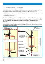
Page 25: ...schlusses erstreckt sich vom Anschluss des Kopfstückes bis zu dem im Stütz rohr integrierten PA Federelement siehe Bild 12 Detail A und B und kann von außen betrachtet über den gesamten Verlauf des GFK Rohres ange nommen werden Über die mechanische Federkontaktierung des PA Federelements an die HVI Leitung halbleitender Spezialmantel erfolgt die Absteuerung gegen das Bezugspotential durch Kontakti...

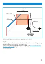
Page 26: ...ndhalter Bild 13 Getrennte Fangeinrichtung mit HVI Leitung und Wandhalterung Schutzwinkel α nach DIN EN 62305 3 VDE 0185 305 3 Blitzschutz Teil 3 Tabelle 2 z B Fangstange NIRO Ø 22 16 10 mm L 2500 mm z B Wandbefestigungswinkel NIRO Klemmbereich Stützrohr Ø 40 50 mm mit Doppelüberleger Art Nr 105 344 Doppelüberleger für PA Anschluss für den Anschluss von 2x Rd 8 10 mm Erdanschlusselement HVI Leitun...

Page 27: ...erbeinstative können aus der Montageanleitung Publication 1842 entnommen werden Die Montageanleitung steht im Download Bereich von DEHN unter www dehn de Produkte HVI Blitzschutz oder Produktsuche Eingabe der Art Nr weitere Informationen zur Verfügung Exemplarisch für Drei Vierbeinstative Höhe 1750 mm Stützrohr einschieben Stützrohr festschrauben Stützrohr Stützrohr Klemmschelle abgeschraubt HVI L...

Page 28: ...urch den variablen Endverschluss und der daraus resultierenden kürzeren Länge des Endverschlusses kann auf die Montage des zusätzlichen Distanzhalters verzichtet werden Die Länge des variablen End verschlusses ergibt sich aus dem errechneten Trennungsabstand in SLuft multipliziert mit dem Faktor 2 Länge L Endverschluss Trennungsabstand in SLuft x 2 Achtung Der variable Endverschluss kann nur bei e...

Page 29: ...wird dadurch kleiner Für diese Anwendung ist die HVI long Leitung Trommelware vorgesehen Siehe Bild 16 und Bild 18 und auch den Beipackzettel Publication No 1851 variabler Endverschluss Die Getrennte Ringleitung muss z B auf der Dachebene unter Berücksichtigung des errechneten Trennungsabstandes s auf Distanzhaltern und Betonsockel verlegt werden Bild 16 Variabler Endverschluss mit Distanzhalter A...

Page 30: ...m Bereich des variablen Endverschlusses sind keine zusätzlichen mechanischen Befestigungen zuläs sig α α Variabler Endverschluss L SLuft x 2 35 cm 150 cm Verbindung zum Potentialaus gleich des Gebäudes Getrennte Ringleitung Anschlusselement Distanzhalter S Luft ...

Page 31: ...ublication 1851 entnommen werden Die Montageanleitung steht im Download Bereich von DEHN unter www dehn de Produkte HVI Blitzschutz oder Produktsuche Eingabe der Art Nr weitere Informati onen zur Verfügung min Länge L S Luft Variabler Endverschluss L SLuft x 2 35 cm max 90 cm Standard HVI Leitung Verbindung zum Potentialausgleich des Gebäudes Attika Anschlusselement S Luft Leitungshalter z B Art N...

Page 32: ... Zur Absteuerung ist eine elektrisch leitende Verbindung zum nächstgelegenen Potentialausgleich Potentialausgleichsebene der Anlage zwingend erforderlich Der Anschluss des Erdanschlusselementes der HVI Leitung erfolgt an die Erdungsanlage z B mit einer UNI Trennklemme Art Nr 459 129 Bild 19 Bereich des Endverschlusses an einer Gebäudestruktur Ableitung Bereich Endverschluss 1500 mm s PA PA Anschlu...

Page 33: ...hlossen werden Von dieser Getrennten Ringleitung können dann mehrere Ableitungen zur Erdungsanlage geführt werden Dies bewirkt eine Reduzierung des Stromaufteilungskoeffizienten kc ab der Höhe der Getrennten Ringleitung Der Trennungsabstand s wird dadurch kleiner Die Getrennte Ringleitung muss z B auf der Dachebene unter Berücksichtigung des errechneten Trennungsabstandes s auf Distanzhaltern z B ...

Page 34: ...34 7 HVI Leitung im Stützrohr Länge 3 2 m errichtet im Dreibeinstativ Bild 20d Bild 20 20 a 20 b 20 c 20 d 25 Nm Strebenverankerung ...

Page 35: ...3 Tab 2 Fangspitze NIRO L 1000 mm Art Nr 101 001 Stützrohr GFK AI 1000 mm Aufnahmestück Arretierungsschraube 25 Nm Sechskantmutter 25 Nm HVI Leitung Biegeradius beachten Befestigungskeil Strebenverankerung Betonsockel Art Nr 102 010 17 kg Strebe Unterlegplatte Art Nr 102 050 Hinweis Das Dreibeinstativ muss mit dem Potential ausgleich Erde verbunden werden 3 2 m ...

Page 36: ...chrauben der metallenen Leitungshalter sind mit max 5 Nm anzuziehen die Befesti gungsschrauben der Kunststoff Leitungshalter mit max 2 Nm Wird die HVI Leitung in der baulichen Anlage verlegt sind bauseits festgelegte Schutzmaßnahmen z B Brandschottungen zu beachten 8 1 Zusätzlicher Anschluss des äußeren Kabelmantels zum Zwecke des Potentialausgleiches Es wird empfohlen bei Kreuzungen oder parallel...

Page 37: ...enden ist Die Böenwindgeschwindigkeit ist somit in Abhängigkeit von dem jeweiligen Objekt zu bestimmen In formationen hierzu finden Sie in den jeweiligen Produktkatalogen Hinweis Windlastberechnungen basierend auf dem Eurocode sind auf Grund länderspezifischer Definitionen unterschiedlich Länderspezifische Unterschiede sind zwingend zu berücksichtigen Deshalb müssen je nach Bauart der Anlage die e...

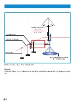
Page 38: ... Max Böenwindgeschwindigkeit 1x HVI innen bis 190 km h Max Böenwindgeschwindigkeit 4x HVI außen bis 163 km h Bild 23 Windgeschwindigkeit Variante I und II bei der Befestigung am Stützrohr Antennenmast Antenne Stützrohr HVI long 1000 mm 2 5 m 0 5m 2500 mm α α α α Verbindung zum Potentialausgleich des Gebäudes Erdungsanlage Variante I Stützrohr mit Fangspitze z B Art Nr 105 330 105 332 NIRO ø 10 mm ...

Page 39: ...VI light Leitung DEHNcon H HVI Leitung HVI power Leitung s 0 9 m in Luft s 1 8 m fester Baustoff 4 Ist im Bereich des Endverschlusses der errechnete Trennungsabstand eingehalten fiktive Reuse 5 Ist das Stützrohr und ggfs das PA Anschlusselement des Endverschlusses korrekt nur mit dem Potentialausgleich der Blitzschutz Potential Ausgleichsebene der Anlage verbunden 6 Ist bei parallel geführten HVI ...

Page 40: ...Überspannungsschutz Hans Dehn Str 1 Tel 49 9181 906 0 Blitzschutz Erdung Postfach 1640 www dehn de Arbeitsschutz 92306 Neumarkt DEHN schützt Germany ...

Page 41: ...ternational com GB Lightning protection earthing Installation instructions HVI Conductor HVI Conductor pre assembled HVI long Conductor Publication No 1841 Update 07 19 Mat No 3003899 Copyright 2019 DEHN SE Co KG ...

Page 42: ...Conductors 15 4 Assembly pre assembly of HVI Conductors 16 4 1 Mounting the head piece connection element 16 4 2 Wrapping a heat shrinkable sleeve around the head piece connection element 17 4 3 Removing the grey sheath for installing HVI long Conductors in the supporting tube 18 4 4 Supporting tubes with air termination tip rod 19 5 Installation 20 5 1 Installing HVI long Conductors in the suppor...

Page 43: ... 7 Installation of HVI Conductors integrated in the supporting tube 3 2 m long in a tripod 34 8 Conductor installation 36 8 1 Additional connection of the external cable sheath for equipotential bonding 36 8 2 Wind load 37 9 Checklist for installing HVI Conductors 39 ...

Page 44: ...ation conditions must be observed for these flammable locations These special installation conditions for HVI Con ductors are described in our Lightning Protection Earthing main catalogue HVI Lightning Protecti on for Thatched Roofs   If the supporting tube is led through a roof the roof must be properly sealed Warm roofs must be properly sealed and insulated   HVI Conductors are suitable for ...

Page 45: ...l installation conditions must be obser ved see installation instructions No 1501   The function of HVI Conductors is to maintain the separation distance Due to their design they do not have a magnetic shielding effect Induction effects in secondary conductors loops must be observed If required surge protection measures must be taken   For application specific questions please contact the rele...

Page 46: ... IEC 62305 3 subclause 6 3 with a material factor of km 1 in air or km 0 5 for solid material It must be checked whether this calculated separation distance can be implemented with the equivalent separation distance of the HVI Conductor see technical data Table 1 page 7 calculated separation distance equivalent separation distance If this is not the case the measures described in 5 3 page 25 must ...

Page 47: ...rmanent temperature range in case of fixed installation 30 to 70 C Ambient and conductor temperature during installation and processing 5 to 40 C Maximum tensile load 950 N Solid stranded inner conductor copper 19 mm Table 1 Technical data of HVI Conductors 2 3 Chemical properties Black RAL 9011 Grey RAL 7035 Reaction to fire self extinguishing No Yes Weather proof UV stabilised Yes Fire load 3 6 ...

Page 48: ...formation is binding Conductors cannot be returned since they are tailored to customer needs pre as sembled conductor lengths Pre assembled HVI Conductors are available with a standard minimum length of 6 m and can be customised in 0 5 m steps The standard minimum length of 6 m must be used in combination with a 3 2 m long supporting tube A loose connection element heat shrinkable sleeve and hexag...

Page 49: ...pplication Whenever the air termination system of the external lightning protection system is directly connected to the earth termination system Table 3 Pre assembled HVI Conductor e g black HVI Conductor Overview HVI Conductor with special sheath fixed head piece Loosely delivered Connection element Heat shrinkable sleeve Hexagon socket wrench head piece and HVI Conductor covered with a heat shri...

Page 50: ...Spacer with EB element Field of application This conductor is used for connecting e g several parts of an installation requiring protection jointly to the earth termination system of the building via an isolated ring conductor see Fig 17 page 28 Conductors with a sealing end mounted in the supporting tube and a sealing end to be adjusted on site are typically used whenever the total conductor leng...

Page 51: ...ions On site assembly 819 131 Black RAL 9011 6 70 m Cut to length according to the customer s specifications packed 819 136 Grey RAL 7035 100 m Disposable reel with an outer dia meter of approximately 800 mm Reel width approximately 485 mm including 1 hexagon socket wrench and installation instructions On site assembly 819 132 Grey RAL 7035 6 70 m Cut to length according to the customer s specific...

Page 52: ...outside the supporting tube head piece for connecting plate and connection element for other parts of the external lightning protection system or earth termi nation system two black heat shrinkable sleeves and four cable ties included 819 148 Connection set grey Head piece and connection element to be connec ted to both ends of the HVI long Conductor when mounting the sealing end of the conductor ...

Page 53: ...rs outside the supporting tube grey Head piece for connecting the HVI long Conductor when mounting the sealing end of the conductor outside the supporting tube 2 heat shrinkable sleeves black grey included head piece for connection plate Thread M12 819 199 Connection element black Connection element for connecting the HVI long Conductor when mounting the sealing end of the conductor 1 black heat s...

Page 54: ...ng end of the HVI Con ductor by means of an MV clamp for Rd 16 mm Rd 8 10 mm 597 220 HVI strip 20 Stripping tool for solid stranded conductors 597 032 HVI cutter Cable pliers for cutting HVI Conductors to length 597 230 DEHNhelix Tool for stripping the additional grey sheath of the HVI Conductor Table 7 Connections elements for HVI long Conductors single parts Note The complete component portfolio...

Page 55: ...holder with longitudinal slot stainless steel Ø 20 23 mm longitudinal slot Ø 5 5 x 10 mm 275 259 Conductor holder for HVI Conductors Wall mounted conductor holder with plastic base stainless steel Ø 20 23 mm 202 829 Roof conductor holder Roof conductor holder with perforated bending points for installing HVI Conductors on gable roofs stainless steel Ø 20 23 mm 253 229 Flat roof holder SET For inst...

Page 56: ...e observed see also Fig 2   Bring the head piece connection element to the HVI Conductor and turn it clockwise onto the re levant conductor end as far as it will go To this end an open end wrench wrench size 19 can be used on the wrench contact surface of the head piece connection element   Tighten the two threaded pins Allen setscrew using a tightening torque of 5 Nm Now the copper conductor ...

Page 57: ...rom the front shrinking area of the relevant head piece connection element to the HVI Conductor The heat shrinkable sleeves must flush with the shrin king area If required they must be repositioned during the shrinking on process  The specified shrinking temperature of max 150 C must be observed  The shrinking temperatures in the shrinking area of the HVI Conductor must not be too high In case o...

Page 58: ...97 230 Fig 4 shows the specified measures for the part to be stripped to electrically contact the semiconductive special sheath These measures must be uncon ditionally observed Figure 4 Installation in the supporting tube These instructions for removing the additional grey sheath must be unconditionally observed If this is not the case the HVI long Conductor is not functional EB spring element int...

Page 59: ... 330 105 314 GRP Al GRP StSt Supporting tube 3 2 m Ø 10 mm Length 1 00 m 4 2 m 105 325 105 336 GRP Al GRP StSt Supporting tube with side outlet 105 331 105 315 GRP Al GRP StSt Supporting tube 3 2 m Ø 22 16 10 mm Length 2 5 m 5 7 m 105 326 105 337 GRP Al GRP StSt Supporting tube with side outlet 105 332 105 316 GRP Al GRP StSt Supporting tube 4 7 m Ø 10 mm Length 1 00 m 5 7 m 105 327 105 338 GRP Al...

Page 60: ...and is electrically connected capable of carrying light ning currents Make sure that there is a sufficient distance about 7 mm between the screw head and the supporting tube after tightening the locking screw The adhesive coating of the screw only hardens after about 5 minutes so that the screw can be correctly positioned and tightened during this period After the adhesive coating has hardened the...

Page 61: ...mm Incorrect assembly locking screw head piece M8 x 25 mm tightening torque of 15 Nm locking screws tightening torque of 15 Nm air termination tip 2x M8x16 mm air termination rod 2x M8x10 mm locking screw head piece M8 x 25 mm tightening torque of 15 Nm air termination rod Ø 22 16 10 mm air termination tip Ø 10 mm HVI long supporting tube head of the supporting tube water proof HVI long Conductor ...

Page 62: ...lso Fig 5 page 21 Installation may not be possible if the screw protrudes too far from the head of the supporting tube   Put the fixing ring with the four slotted conduc tor holders for the sealing end on the top edge of the connecting sleeve through the head of the supporting tube or from below through the supporting tube and pre mount it by means of the M8 screw In this process observe the pos...

Page 63: ...Firmly fix the fixing ring by means of the M8 screw tightening torque of 15 Nm When using a HVI long Conductor or a pre assemb led HVI Conductor with additional grey sheath the outer grey sheath in the area around the slotted cleats must be removed to contact the black sheath The black sheath must not be cut in Figure 9 Step 4 for installing a HVI long Conduc tor outside the supporting tube   Th...

Page 64: ...ient kc similar to a ring conductor thus reducing or maintaining the necessary separation distance s Connection elements e g Part No 819 197 or 819 196 are used for the connections installation outside the supporting tube Figure 11 Connecting cable between the supporting tubes connecting cable connecting cable ...

Page 65: ...ent integ rated in the supporting tube see Fig 12 detail A and B and can be assumed to run along the entire GRP tube Due to the mechanical spring contact acting as an EB element the HVI Conductor semiconduc tive special sheath is connected to the suppor ting tube To this end the supporting tube must be conductively connected with the next equipoten tial bonding system of the installation The condu...

Page 66: ... to IEC 62305 Part 3 Table 2 e g air termination rod StSt Ø 22 16 10 mm L 2500 mm e g wall fixing bracket StSt clamping range supporting tube Ø 40 50 mm with double cleat Part No 105 344 double cleat for connecting 2x Rd 8 to 10 mm to the equipotential bonding system earth connection element HVI Conductor connection to the equipotential bonding system of the building earth termination system α α S...

Page 67: ...ods and four legged stands please refer to installation instructions No 1842 which can be downloaded at www dehn international com en products hvi lightning protection cui conductor in the download section or enter the relevant Part No in the Product search of our homepage Example of Tripods four legged stands height of 1750 mm insert supporting tube tighten supporting tube supporting tube support...

Page 68: ... 15 Variable sealing end Due to the variable sealing end and the resulting reduced length of the sealing end no additional spa cer must be installed The length of the variable sealing end is determined by multiplying the calculated separation distance in sair by the factor 2 Length L of the sealing end separation distance in sair x 2 Attention The variable sealing end can only be used for black HV...

Page 69: ...wnstream of the isolated ring conductor and the separation distance s is also reduced HVI long Conductors on a reel can be used for this purpose see Fig 16 and 18 and instruction leaflet No 1851 variable sealing end The isolated ring conductor must be installed on spacers and concrete bases e g on the roof level The calculated separation distance s must be observed Figure 16 Variable sealing end w...

Page 70: ...nt Note Additional mechanical fixing is not allowed in the variable sealing end α α variable sealing end L Sair x 2 35 cm 150 cm connection to the equipotential bon ding system of the building isolated ring conductor connection element spacer S air ...

Page 71: ...h can be downloaded at www dehn international com en products hvi lightning protection cui conductor in the download section or enter the relevant Part No in the Product search of our homepage min length L S air variable sealing end L Sair x 2 35 cm max 90 cm standard HVI Conductor connection to the equipotential bonding system of the building capping of the roof parapet connection element S air c...

Page 72: ...m equipotential bonding level of the installation is required A UNI disconnecting clamp Part No 459 129 can be used to connect the earth connection element of the HVI Conductor to the earth termination system Figure 19 Sealing end range on a building s structure down conductor sealing end range 1500 mm s EB EB connection element Detail A Part No 410 229 earth connection element Detail B HVI Conduc...

Page 73: ...ion system can be connected to e g an isolated ring conductor From this isolated ring conductor several down conductors can be routed to the earth termination system In this case the partitioning coefficient kc is reduced downstream of the isolated ring conductor and the separation distance s is also reduced The isolated ring conductor must be installed on spacers e g Part No 106 175 and concrete ...

Page 74: ...cified tightening torques of 25 Nm see Fig 20 page 34 The supporting tube with tripod HVI Conductor installed inside the supporting tube and up to 4 HVI Conductors installed outside the supporting tube withstands wind speeds up to 142 km h wind load zone II see page 38 In order to ensure the minimum bending radius of the HVI Conductor of 200 mm 230 mm the tripod must be installed in an elevated po...

Page 75: ...c to IEC 62305 3 Table 2 air termination tip StSt L 1000 mm Part No 101 001 GRP AI supporting tube 1000 mm adapter locking screw 25 Nm hexagon nut 25 Nm HVI Conductor observe bending radius fixing wedge bracing concrete base Part No 102 010 17 kg brace base plate Part No 102 050 Note The tripod must be connected with the equi potential bonding system earth 3 2 m ...

Page 76: ... with max 5 Nm the fixing screws of plastic conductor holders with max 2 Nm If a HVI Conductor is installed in the structure existing protection measures e g fire barriers must be observed 8 1 Additional connection of the external cable sheath for equipotential bon ding In case of crossovers or parallel conductor routing towards earthed metal installations such as cap pings of the roof parapet cab...

Page 77: ...ystems Consequently the gust wind speed must be determined depending on the relevant object Information on this topic can be found in the relevant catalogue Note Wind load calculations based on Eurocode differ due to country specific definitions Country specific differences must be observed Therefore the individual components such as air termination rod supporting tube tripod etc must be chosen fo...

Page 78: ...up to 190 km h max gust wind speed 4 x HVI outside up to 163 km h Figure 23 Wind speed Versions I and II when attaching to the supporting tube Antenna mast Antenna Supporting tube HVI long 1000 mm 2 5 m 0 5m 2500 mm α α α α Connection to the equipotential bonding of the building Earth termination system Version I Supporting tube with air termination tip e g Part No 105 330 105 332 StSt ø 10 mm L 1...

Page 79: ...aterial HVI power Conductor s 0 9 m in air s 1 8 m solid material 4 Is the calculated separation distance kept in the range of the sealing end 5 Is the supporting tube and if required the equipotential bonding element of the sealing end correct i e only connected with the equipotential bonding the lightning equipotential bond ing of the system 6 Is the minimum distance of 0 2 m kept between HVI Co...

Page 80: ...Hans Dehn Str 1 Tel 49 9181 906 0 Postfach 1640 www dehn international com 92306 Neumarkt Surge Protection DEHN SE Co KG Lightning Protection Safety Equipment DEHN protects Germany ...

Reviews: