background image

-1-

142766 - PRO-TILL 10|13   (10-February-2022)

Introduction

OPERATOR ORIENTATION 

- The directions left, right, front and rear, as mentioned throughout the manual, 

are as seen from the tractor drivers’ seat and facing in the direction of travel.

CONGRATULATIONS

 on your choice of a Degelman PRO-TILL to complement your farming operation.  It has 

been designed and manufactured to meet the needs of a discerning agricultural market. Degelman PRO-TILL 

shreds heavy fall residue, opens up spring fields, levels ruts, destroys clods and produces an absolutely perfect 

seed bed. Degelman PRO-TILL is the fastest and most versatile piece of tillage equipment you will ever own. 

Use this manual as your first source of information about this machine. 

TO THE NEW OPERATOR OR OWNER 

- Safe, efficient and trouble free operation of your Degelman PRO-TILL 

requires that you and anyone else who will be operating or maintaining it, read and understand the Safety, 

Operation, Maintenance and Troubleshooting information contained within this manual. 

By following the operating instructions in conjunction with a good maintenance program your machine will 

provide many years of trouble-free service. Keep this manual handy for frequent reference and to pass on to 

new operators or owners. Call your Degelman Dealer if you need assistance, information, or additional copies 

of the manual.

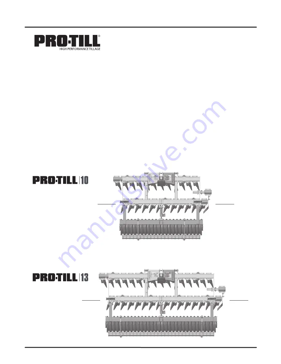
Front 3-point Hitch

Front 3-point Hitch

Roller Assembly

Roller Assembly

LH SIDE

LH SIDE

RH SIDE

RH SIDE

Summary of Contents for PRO-TILL 10

Page 1: ...TS MANUAL D E G E L M A N I N D U S T R I E S L P B O X 8 3 0 2 7 2 I N D U S T R I A L D R I V E R E G I N A S K C A N A D A S 4 P 3 B 1 FA X 306 543 2140 P H 306 543 4447 1 8 0 0 6 6 7 3 5 4 5 D E G E L M A N C O M 142766 v1 0 ...

Page 2: ......

Page 3: ...RRANTY REMEMBER You must complete Product Registration to be eligible for Warranty C Lower Machine D Set Cutting Depth Start with 14 stops Test depth adjust Depth Adjustment Depth Control on Cylinder Typically Set to 2 1 IMPORTANT Cycle oil in the Depth Control Cylinder before use This is especially important after long periods of storage 1 1 NOTE Adjust pin locations to coincide with CAT size of ...

Page 4: ... Properly tighten Hydraulic Connections Hoses Working points pins Check for missing worn or damaged parts Maintenance Check Machine Daily GPS Reference Set overlap to 4 per side with 20 discs 2 Depth Pro Till 10 117 9 98m Pro Till 13 157 3 99m with 20 discs MAX Depth Pro Till 10 119 3 02m Pro Till 13 159 4 04m Refer to operators manual for complete safety and operation info E Test Check Adjust F R...

Page 5: ...TS SECTION TABLE OF CONTENTS Pro Till Section Overview 19 Main Frame Overview 20 Frame Components 21 Disc Gang Assembly Components 22 Disc Arm Components Disc Options 23 Roller Options Components 24 Hydraulic Routing Cylinder 27 Warranty 28 D E G E L M A N I N D U S T R I E S L P B O X 8 3 0 2 7 2 I N D U S T R I A L D R I V E R E G I N A S K C A N A D A S 4 P 3 B 1 FA X 306 543 2140 P H 306 543 4...

Page 6: ...CHANGING DISCS AND SERVICING The best position to safely change or service the discs on the Pro Till is when it is secured onto blocks in the lowered position DANGER NEVER crawl under machine while raised on 3 point hitch DANGER NEVER CRAWL UNDER Pro Till while RAISED on 3 point Hitch ...

Page 7: ...e equipment you will ever own Use this manual as your first source of information about this machine TO THE NEW OPERATOR OR OWNER Safe efficient and trouble free operation of your Degelman PRO TILL requires that you and anyone else who will be operating or maintaining it read and understand the Safety Operation Maintenance and Troubleshooting information contained within this manual By following t...

Page 8: ...utions are not taken WARNING Indicates a potentially hazardous situation that if not avoided COULD result in death or serious injury if proper precautions are not taken CAUTION Indicates a potentially hazardous situation that if not avoided MAY result in minor or moderate injury if proper practices are not taken or serves as a reminder to follow appropriate safety practices Why is SAFETY important...

Page 9: ...cedures and related SAFETY information contained in this manual This manual will take you step by step through your working day and alerts you to all good safety practices that should be adhered to while operating this equipment Remember YOU are the key to safety Good safety practices not only protect you but also the people around you Make these practices a working part of your safety program Be ...

Page 10: ...re installed reverse the tractor slowly until the 3 point arms lock back into place 6 Install connection pins on lower 3 point arms 7 Attach top link with appropriate pin CAT 3 1 1 4 CAT 4 1 3 4 1 1 4 1 3 4 Bushing Store spare pin parts on holder 8 Connect the hydraulic hoses Use a clean cloth or paper towel to clean the couplers on the ends of the hoses Also clean the area around the couplers on ...

Page 11: ...y to allow faster traffic to pass Drive on the road shoulder if permitted by law 6 Always use hazard warning flashers on tractor when transporting unless prohibited by law TRANSPORT SAFETY Use the following guidelines while transporting 1 Fully extend roller cylinder for transport 2 Ensure debris that may fall or become dislodged during transport is removed 3 Be sure hazard lights are flashing and...

Page 12: ...Before using 1 Read Safety Info Operator s Manual 2 Complete steps in Pre Operation Checklist 3 Check all Bolt Tightness 4 Adjust Disc Cutting Depth as outlined in the Setting Disc Depth section B After operating for 2 hours 1 Check all hardware Tighten as required 2 Check all hydraulic system connections Tighten if any are leaking BREAK IN Operation Before operating the machine and each time ther...

Page 13: ...depth depending on the type of crop residue or soil conditions The operator can adjust the cutting depth by following the guidelines in the Setting Disc Depth section 7 After making adjustments to the cutting depth it is recommended to bring the Pro Till up to speed 10 12mph to test the depth setting by driving about 100m cutting performance changes dramatically from a slow speed to high speed Sto...

Page 14: ...ther Adjustments to the front to rear disc section height or pitch are done with the top link of the 3 point hitch Lengthening 3 point top link Lowers the Rear Discs Increases Roller Pressure Shortening 3 point top link Raises the Rear Discs Decreases Roller Pressure NOTE For better performance adjust pitch slightly higher on the front lengthen top link to increase roller pressure DEPTH SETTING OV...

Page 15: ...e scraper blades are designed to be reversible in order to provide extended wear It is advised to order replacement blades soon after reversing to prevent possible downtime in the future Loosen the top bolt to adjust then hold in place while re tightening INDIVIDUAL SCRAPER ARM ADJUSTMENT The individual scraper arm position can also be fine tuned by loosening the top mounting bolt adjusting the po...

Page 16: ...shed up mound smooth out when soil dries Fully extend depth cylinder drive 12 14 mph on firm soil to clear rollers In certain wet soil conditions place scrapers in storage position to continue operating If plugging persists wait for soil conditions to dry out even more Roller skidding in wet conditions Check scraper operation settings Raise machine working depth Adjust pitch so front discs are sli...

Page 17: ... slower or shallower to run faster Pre work heavy trash or wet areas at a slower speed at a different angle than final pass Wait for soil conditions to dry out more Ensure tractor has correct tire pressure and is properly ballasted Rear discs following in front disc cut or discs not doing a full cut Adjust tracking by extending the top 3 point link to track right or retracting the top link to trac...

Page 18: ...hose or a fitting 7 Always relieve pressure before disconnecting or working on hydraulic system 8 Never crawl pass work under implement while raised on 3 point hitch MAINTENANCE SAFETY Service Maintenance DANGER Never crawl pass work under implement while raised on 3 point hitch MAINTENANCE CHECKLIST After reviewing the Maintenance and Hydraulic Safety Information use the Maintenance Checklist pro...

Page 19: ...lated GR5 UNC or P8 8 metric HARDWARE SPECIFICATIONS HYDRAULIC HOSE INSTALLATION TIPS The following tips are to help you identify some possible problem areas in the installation of hydraulic hoses 1 Installation should be completed in a clean environment clear of dust and contaminants Hoses and fittings should be capped if not installed 2 Ensure hoses are not twisted during installation as this ma...

Page 20: ...aged 3 Lubricate threads and O ring to help the O ring slide past the port entrance corner and avoid damaging it 4 Screw the fitting into position tighten to proper torque value from the table shown above Adjustable Port End Assembly 1 Inspect the components to ensure male female threads and sealing surfaces are free of nicks burrs scratches or any foreign material 2 Ensure O Ring seal is properly...

Page 21: ... new components 7 Inspect the inside of the cylinder barrel piston rod and other polished parts for burrs and scratches Smooth areas as needed with an emery cloth REASSEMBLY 1 Reinstall rod through end cap gland assembly 2 Secure piston to rod with lock nut Torque lock nut to proper value refer to chart for proper torque value 3 Lube inside of barrel piston seals and gland seals with hydraulic oil...

Page 22: ...s properly aligned press into hole preferred method or hammer into position by striking the stepped tool 6 Continue to install until the bushing edge is recessed in to a distance of 5 16 to allow for the outer seal to be properly installed Do not exceed this depth 7 Repeat steps 4 6 for opposite bushing if applicable 8 When both bushings are installed to the proper depth install the new seals 9 Re...

Page 23: ...Disc Depth 1 Serial Number Plate DECAL LOCATION OVERVIEW 143162 Decal Read Manual 1 142965 Decal Danger Crushing Hazard 1 142966 Decal Warning Pinch Point 1 142689 Decal Warning Fully Extend 1 142556 Decal Reflector Red 2 x 9 2 142557 Decal Reflector Amber 2 x 9 4 142650 Decal Fluorescent 2 x 9 2 142988 Decal Disc Depth 1 142008 Decal Degelman 6 1 142010 Decal Degelman 2 3 4 2 142771 Decal Pro Til...

Page 24: ... 18 142766 PRO TILL 10 13 10 February 2022 ...

Page 25: ... 13 Pro Till Pro Till Overview 3 point Frame 3 point Frame Disc Gangs Disc Gangs Dirt Deflector Dirt Deflector Roller Assembly Depth Cylinder Depth Cylinder Roller Assembly Rubber Roller shown above Cage Roller option also available Rubber Roller shown above Cage Roller option also available ...

Page 26: ... Pin Component Holder Hose Storage Hose Storage 575195 Pin Shaft 1 1 2 x 6 1 4 2 249954 Pin Shaft 1 1 2 x 5 1 4 2 249950 Pin Head 2 249950 Pin Head 2 Mounts with Mounts with 118775 Flat Washer 3 4 F436 4 118775 Flat Washer 3 4 F436 4 118048 Bolt 3 4 x 2 1 2 GR8 2 118743 Bolt 3 4 x 2 1 4 GR8 2 117414 Lock Nut 3 4 Unitorq 2 117414 Lock Nut 3 4 Unitorq 2 118483 Lock Nut 1 4 Unitorque 4 118541 Flat Wa...

Page 27: ...ly 2 129125 Dual Lamp LH 1 118483 Lock Nut 1 4 Unitorque 8 118555 Flat Washer 1 4 16 118756 Bolt 1 4 x 1 1 4 8 129126 Dual Lamp RH 1 572404 Disc Arm Clamp Plate 1 117580 Bolt Carriage 5 8 x 2 1 4 GR8 4 143549 Rubber Insert 4 117438 Carriage Bolt 3 4 x 2 1 2 GR8 4 118635 Flat Washer 3 4 x 2 1 4 2 118635 Flat Washer 3 4 x 2 1 4 2 118775 Flat Washer 3 4 F436 4 117414 Lock Nut 3 4 Unitorque 2 117414 L...

Page 28: ...Frame 1 c w 572909 Gang Mounting Frame 1 Back Row 15 Disks 1 Outer RH Front Row 16 Disks 572891 V Clamp 1 118911 Lock Nut 1 GRC 2 118134 Bolt 1 x 3 GR8 2 Gang Assembly Mounting 8 131020 Flat Washer 1 F436 4 Gang Mounting Frame Included in Gang Section Assembly 13 Pro Till Disc Gang Overview Back Row 11 Disks 1 Outer RH 572907 Gang Section Assembly 1 c w 572910 Gang Mounting Frame 1 Setting Gang Se...

Page 29: ...2 End Discs Straight 143562 1 20 Rear RH End Disc 143556 Note Customers may wish to adjust the end disc sizes and locations for customer preferred performance in certain soil or field conditions 143550 118279 Bolt 1 2 x 1 1 2 GR8 4 131415 Disc Hub Unit 1 143556 Disc 20 1 143549 Rubber Insert 4 118635 Flat Washer 3 4 x 2 1 4 1 118468 Nut 1 2 Flange 4 117580 Bolt Carriage 5 8 x 2 1 4 GR8 4 117581 Lo...

Page 30: ...Frame Assembly 13 1 10 Rubber Roller 131845 Rubber Roller Assembly LSTX 3m 1 shown 3m or 4m Scraper Section 13 Rubber Roller 131855 Rubber Roller Assembly LSTX 4m 1 117579 Bolt Carriage 5 8 x 2 1 2 GR8 8 118447 Lock Nut 5 8 Unitorque 8 572428 Washer Endplate 2 Hole 2 572786 Spacer Bushing 2 117171 Bearing Unit 4 Hole 2 117172 Bearing Insert 2 7 16 1 118186 Bolt 1 2 x 1 1 4 GR8 4 IMPORTANT Add Blue...

Page 31: ...1723 Axle Lock Washer 2 Roller End Rubber Rubber Roller End Assembly Components 131896 Repair Toolkit 1 required for removal of endplate 131816 Tube Assembly 4m 1 131730 Tube Assembly 3m 1 Tube Frame Assembly Rubber Roller Frame Components 572446 End Axle Shaft Assembly 2 118048 Bolt 3 4 x 2 1 2 GR8 6 118775 Flat Washer 3 4 F436 12 117414 Lock Nut 3 4 Unitorque 6 Cage Roller End Assembly Component...

Page 32: ...2 x 1 1 4 GR8 23 or 31 IMPORTANT Add Loctite to threads Torque to 90 lb ft 120 N m 117599 Lock Washer 1 2 Nordlock 23 or 31 110067 Washer Scraper Cast 23 or 31 Double Scraper Blade Kits c w Bolts Locknuts Kits 10 572755 23 13 572756 31 Scraper Blade Replacement Options 2 Max Life Replacement Scraper Blades requires new hardware Locknuts 572957 Scraper Blade Max Life 1 4 118186 Bolt 1 2 x 1 1 4 GR8...

Page 33: ...03 Adaptor 1 2 ORB M x ORFS M 2 110 115 Roller Depth Cylinder Components IMPORTANT INSTALL DRY Do NOT use any oil grease lubricant on pin or bushing surfaces when installing the maintenance free pins into composite bushings Maintenance Free Pins Bushings 123740 Cylinder Monarch 3 x 4 x 1 1 2 2 117240 Bushing 2 OD x 3 3 8 2 133134 Wiper Seal 2 OD 4 Seal Kit 123665 118417 Lock Nut 3 8 2 118511 Flat ...

Page 34: ...pplies rental machinery or loss of use No other warranty of any kind whatsoever express or implied is made with respect to this sale and all implied warranties of merchantability and fitness for a particular purpose which exceed the obligations set forth in this written warranty are hereby disclaimed and excluded from this sale This exclusion shall not apply in any jurisdiction where it is not per...

Page 35: ... for service or replacement of defective parts which are covered by warranty Repairs to be submitted for warranty consideration must be made within forty five days of failure It is the Retail Customer s responsibility for any cost incurred by the dealer for hauling of the product for the purpose of performing a warranty obligation or inspection WARRANTY INFORMATION Make certain the warranty regist...

Reviews: