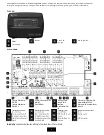
DEGA UPA III User Manual Download Page 8


2.


LCD display 


Time 


Date 


Secondary display 


Warning: calibration 
required 


RS485 address of the 
current transmitter 


„Channel“ of the 
current transmitter 


Interrupted RS485 
bus indication 


Transmitter calibration 
via RS485 


Marker (selecting a 
transmitter in the 
menu) 


Malfunction of the 
controller or a 
connected transmitter 


Exceeding the 
critical temperature 
level 


Indication of an alarm 
record in the history 


Flooding indication 


Exceeding the time-
weigted avarage 


Alarm PEL - long-
term exposure limit 
Alarm STEL - short-
term exposure limit 


Gas leek alarm 


Type of detected gas / 
substance 


Measured units 


Main segments of 
the display, 
currently measured 
concentration 


3.


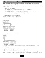
Launch of the controller 

After turning on the power supply, the whole LCD Display lights up and loads the highest meassured concentration, which 
remains on the display for cca 3s. After that the controller goes into preheating mode. The main LCD displays a countdown to 
the end of preheating and the secondary segments display the inscription „HEATING“.  
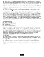
4.


Basic status/alarms 

The controller displays the concentration on 4 main segments. To it's right, units and the detected gas are being displayed. The 

8 auxiliary segments display the location or an evnetual sensor malfunction. If the displayed channel is digital 

 (1 to 

32), the adress 

 of the connected sensor is also displayed. Connected analog transmitters 

 have a range 

of 41 to 48. The controller sequentially switches the configured channels in a 3s interval.  If we want to select a transmitter 
manually, we can do so with the buttons LEFT and RIGHT. 
The status of the sensor bundled with an output relais (alarms, time-weigted avarages, statuses of temperature sensors and 
floodings, malfunctions) is displayed in the right part of the LCD.  
In case of an increased concentration, the LED ALARM starts shining and the controller switches to the channel, which 
meansured this concentration. After 30s the channels will again be sequentially switched. 

The latch function

 – catalytic and semiconducter sensors can, when exceeding the measuring range, indicate a lower 

measured value than it really is. If the measured concentration of these sensors exceed 100% of the lower explosion level, the 
latch will activate. Even after a drop of the measured concentration, the transmitter will still be in it's highest alarm level. The 
detection area must be physically checked by an independent transmitter and after that the controller can be unblocked by 
pressing the ENTER button. 
The ENTER button also serves as a confirmation button for the acoustic alarm. 

17 

19 

18 

13 

16 

15 

14 

12 

11 

10 

Summary of Contents for UPA III

Page 1: ...ny form without the prior permission of DEGA CZ s r o is prohibited DEGA CZ s r o reserves the right to alter the specifications of the hardware and software described in this manual at any time and without prior notice DEGA CZ s r o bears no liable for any damage resulting from use of this device ...

Page 2: ... past alarms 9 9 Automatic adjustment of the 0 point 9 10 Menu 9 History Menu HIST 10 Information menu INFO 10 Configuration menu CONF 10 Controller testing menu TEST 11 Service Menu SERV 11 Maintenance 12 1 Operation Maintenance 12 2 Replacement of the battery 12 Attachments 13 1 Table of error codes 13 General warranty terms and conditions 14 For your safety Beware of static electricity Electron...

Page 3: ... 25 mm max 100 m Cable for connecting signalization a pushbutton cable 2 x 1mm Output USB for PC configuration RS485 protocol DEGA or MODBUS on request for the host system PLC PC 10x switching relays 250 V 10 A 2x outupt for visual and acoustic alarms max load see chapter Assembling and connecting the wiring paragraph 6 Communication speed of RS485 9 6 kB Functional safety EN61508 SIL 1 Dimensions...

Page 4: ...e suppy voltage 22 26V Terminal block relay RE8 RE10 Fuse T400mA Auxiliary input output 24V DC Power supply terminal block 230VAC Temperature sensor terminal block Acoustic alarm lay key terminal block Flooding sensor terminal block Acoustic alarm terminal block Bus temrinal block 1 for digital transmitters Bus temrinal block 0 for digital transmitters RS485 for the host system Analog inputs Optic...

Page 5: ...e cover of the case and lock the controller by using the handle 2 Connecting a transmitter via current loop Connect one transmitter on each channel of the controller 3 Connecting a transmitter via RS485 It is possible to connect up to 16 transmitters on each controller input depending on their electrical distance from the controller Wiring installation for RS485 Wiring must be done using bus topol...

Page 6: ... the supply voltage and the maximum current load Supply voltage 230V AC The highest current load of the controller is 1 4A This current serves to power the connected transmitters and the visual and acoustic alarms which are connected to the terminal blocks LIGHT_SIG and SOUND_SIG Example There are 4 transmitters connected to the controller with a consuption of 60 mA each The remaining 1 16 A I 140...

Page 7: ...imru můžeme regulovat výstupní napětí zdroje v rozsahu 22 26V V případě že jsou snímače připojeny na velkou vzdálenost může být pro správnou funkci nutné zvýšit napájecí napětí Controls The control panel is equipped with a segmented LCD display and can be controlled using the LEFT RIGHT and ENTER buttons In Basic mode the controller displays the concentration and the states of the configured chann...

Page 8: ...cation or an evnetual sensor malfunction If the displayed channel is digital 1 to 32 the adress of the connected sensor is also displayed Connected analog transmitters have a range of 41 to 48 The controller sequentially switches the configured channels in a 3s interval If we want to select a transmitter manually we can do so with the buttons LEFT and RIGHT The status of the sensor bundled with an...

Page 9: ...larm occurred the icon is displayed To view these alarms enter the menu HIST HILA where the date and time since the highest measured alarm since reseting HIST _RST is displayed for each transmitter After viewing the history it s possible to reset the counter throught HIST _RST and the icon disappears 9 Automatic adjustment of the 0 point The connected digital transmitters have an inner diagnostic ...

Page 10: ...n to return the the history menu Note In case of equipping a larger quantity of transmitters the loading of the history may take a few seconds Information menu INFO NCAL Displays the date of the next transmitter calibration LCAL Displays the date of the calibration TEMP Displays the temperature of the DEGA Tc II sensor ADDR Displays the controller address on the RS485 HOST bus EXIT Returns to a hi...

Page 11: ...nged with LEFT and RIGHT and using ENTER will confirm the selection In the final part of this whole process select either YES for saving the values into the transmitters or no for finishing the calibration without saving the values Controller testing menu TEST RELE Setting the relay output TRAN Simulation of the measured values _RST Controller restart EXIT Returns to a higher menu level The entry ...

Page 12: ...required accuracy and the occurrance of disturbing gases in the atmoshpere Also carry out a functional control 1 x every three months checking the function of the entire detection system using a test gas which does not exceed the range of the sensor We recommend using gas intended for laboratory use For the functional control do not use means for testing fire alarm detectors Perform calibration on...

Page 13: ... error contact the manufacturer X SEN MISM The set sensor ID does not match with the connected sensor Checking the configuration of the sensor required X ELFAILED EL sensor test error Sensor error only informative subsides by itself X X HEATING Transmitter is in preheating mode Wait a few minutes the transmitter will automatically enter measurement mode X EE25 ERR Error reading the internal FLASH ...

Page 14: ...ct shall be replaced 616 paragraph 4 of the Commercial Code 6 The buyer who exercises the right of warranty repair is not entitled to the return of the parts that have been replaced 7 The warranty period can be extended for up to 48 months and its validity can be extended beyond the standard length on the basis of the conclusion of an individual warranty contract Further information may be obtaine...

Reviews: