


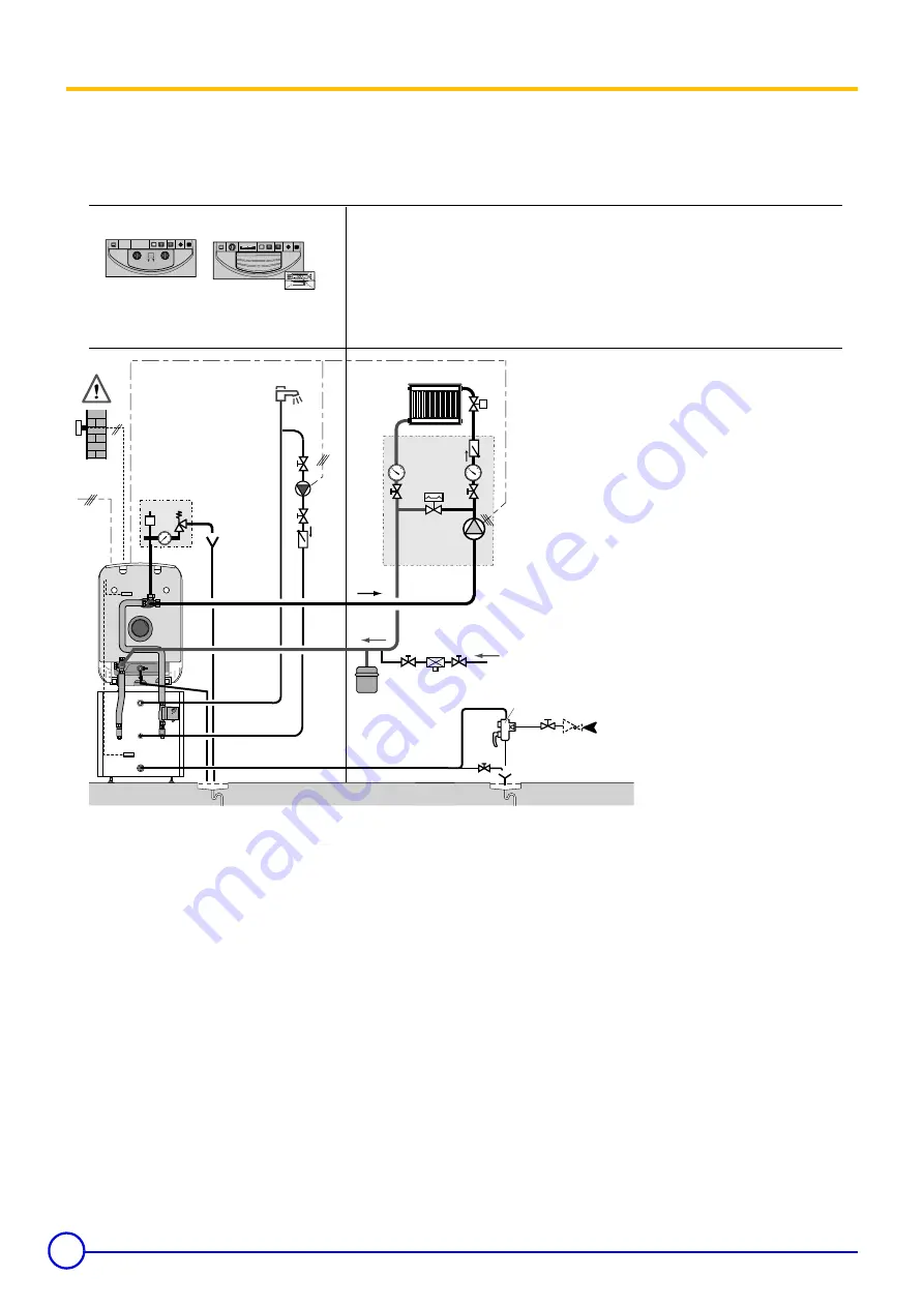
2 Example of installation
The following diagram is given as example. Other connections could be made.
.
Installation with 1 direct radiator heating circuit (without mixing valve)
This type of installation can be controlled by a B control panel (base standard) or an E control panel (Easymatic)
1
Heating supply
2
Heating return
3
3-bar safety valve
4
Manometer
7
Automatic bleeder valve
9
Valve
11
Heating accelerator
16
Expansion tank
17
Draining valve
18
Heating circuit filling valve
21
Outside temperature sensor
- no probe with B panel
- delivered as original equipment with E panel
22
Control unit boiler sensor
26
Domestic pressurizer pump
27
Non-return valve
28
Domestic cold water inlet
29
Pressure reducer
30
Sealed safety device calibrated to 7 bars
32
(Optional) dhw looping pump
33
Delivered domestic hot water temperature probe
50
Disconnector
51
Thermostat valve
52
Differential safety valve
50
51
18
17
9
9
9
52
11
16
2
1
3
4
21
50Hz
230V
22
26
33
27
7
¡C
¡C
17
9 29
28
30
9
9
27
32
5
4
3
7
9
20
¡C
40
0
I
4A
STANDARD
MODE
PROG
PROG
+
-
1
2
3
4
5
6
7
0
2
4
6
8
10
12
14
16
18
20
22
24
0
I
4A
4
5
6
7
8
1
2
3
3
4
5
6
7
8
9
B
E
Easymatic
8578N026
Base standard
Original panel without options
20
GT 120 A - GT 1200 A
09/02/08 - 94863361 - 85784009D
Summary of Contents for GT 123 A
Page 35: ...35 09 02 08 94863361 85784009D GT 120 A GT 1200 A CASING INSULATION...
Page 38: ......
Page 39: ......


