background image

Chapter 2. RAID Array Controller

EK–SMCPO–UG. A01

2–21

 While downloading the data, the controller responds to I/O by disconnecting (if
allowed) and waiting approximately three seconds before reconnecting and pre-
senting a BUSY status.  The delay is to prevent host operating systems from
seeing too many errors and fencing off the controller.

 2.9

Environmental

 The controller incorporates a set of on board sensors to detect abnormal operat-
ing conditions that may affect data safety.

 2.9.1  Backup Power Management

 The controller must be connected to a backup battery and/or Uninterruptable
power supply (UPS) to prevent the subsystem cache from being corrupted during
unexpected losses of power. If no backup power supply is provided, the control-
ler will remain off-line and reject all I/O requests with a status of Check Condi-
tion/Hardware Error.

 If the backup power source indicates that power may be failing, the controller’s
first step is to sound an alarm, enter write through mode and begin flushing
cache. If the backup power source reaches a critical state, the alarm frequency
increases and all host channels are disabled to prevent new requests from inter-
fering with the cache flush.

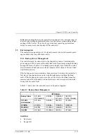
 Table 2–7 shows how the controller reacts to the power supplies.

 Table 2–7  Backup Power Management


 UPS Status

 Battery Status

 OFFLINE
(Not Installed)

 NORMAL

 WARNING
(AC Lost)

 SEVERE
(2-Min. Warning)

 OFFLINE
(Not Installed)

 OFFLINE

 NORMAL

 SEVERE

 OFFLINE

 NORMAL

 NORMAL

 NORMAL

 WARNING

 WARNING

 WARNING

 SEVERE

 WARNING

 WARNING

 SEVERE

 SEVERE

 OFFLINE

 WARNING

 SEVERE

 OFFLINE


 NORMAL

• 

No Alarms

• 

Normal I/O


Summary of Contents for DS-HSZ22-AA

Page 1: ...RAID Array 3000 Storage Subsystem Hardware User s Guide EK SMCPO UG A01 Digital Equipment Corporation Maynard Massachusetts ...

Page 2: ...l Equipment Corporation makes no representation that the use of its products in the manner described in this publication will not infringe on existing or future patent rights nor do the descriptions contained in this publication imply the granting of licenses to make use or sell equipment or software in accordance with the description The following are trademarks of Digital Equipment Corporation D...

Page 3: ... 1 4 4 Uninterruptable Power Supply 1 7 1 4 5 Environmental Monitor Unit EMU 1 8 1 4 6 UltraSCSI Bus 1 9 1 5 Specifications 1 12 2 RAID Array Controller 2 1 Controller Overview 2 1 2 2 Controller Features 2 2 2 3 Controller Reset and LED Indicators 2 6 2 4 Flexible RAID Set Configuration 2 7 2 5 Performance Enhancements 2 8 2 5 1 Custom Components 2 8 2 5 2 Efficient Write and Read Algorithms 2 8 ...

Page 4: ...ng 2 24 3 Maintenance 3 1 Introduction 3 1 3 2 Pedestal Status and Power LEDs 3 2 3 3 SBB Status LEDs 3 2 3 4 Controller LEDs 3 3 3 5 EMU Error Reporting 3 4 3 6 EMU Error Conditions 3 4 3 6 1 Replacing Components FRU s 3 5 3 6 2 Removing the Pedestal Door 3 5 3 6 3 Replacing an SBB 3 6 3 6 4 Replacing a Power Supply 3 7 3 6 5 Replacing the RAID Array Controller 3 8 3 6 6 Replacing the EMU Board 3...

Page 5: ...omponents 1 9 1 6 UltraSCSI Bus Configuration Switch 1 10 1 7 Slot Locations and SCSI ID Addresses 1 10 1 8 Slot Locations and SCSI ID Addresses 1 11 2 1 Bridging the Gap Between the Host and the Pedestal 2 2 2 2 Units Created from Storagesets Partitions and Disk Drives 2 3 2 3 Controller Front Panel 2 7 2 4 RAID 0 Write 2 12 2 5 Diagram of a RAID 1 Write 2 13 2 6 Diagram of a RAID 0 1 Write 2 14 ...

Page 6: ...ower Supplies 4 4 4 4 EMU Circuit Board Location 4 5 4 5 Remove Side Cover from Base Pedestal 4 7 4 6 Remove SCSI Bus Terminator 4 7 4 7 Disconnect SCSI Cable 4 8 4 8 Connect SCSI Jumper 4 8 4 9 Remove Connector Knockout Plate 4 9 4 10 Connect SCSI Cable 4 10 4 11 Set Configuration Switch to 7 4 10 4 12 Configuration Switch 4 11 4 13 Reconfigured SCSI Bus Addresses 4 11 4 14 Connect SCSI Cable Bet...

Page 7: ...estal RAID Set Restrictions 2 10 2 5 RAID 0 1 Example 2 14 2 6 System Parameters 2 19 2 7 Backup Power Management 2 21 2 8 Acceptable System Voltage Levels 2 22 2 9 Acceptable Termination Voltage Levels 2 23 2 10 Acceptable 12 Volt Levels 2 23 2 11 Acceptable External Temperature Voltage Levels 2 24 2 12 Acceptable Board Temperature Voltage Levels 2 24 3 1 Disk Drive SBB Status LEDs 3 3 3 2 SCSI B...

Page 8: ......

Page 9: ...ons The following revision history lists all revisions of this publication and their effective dates The publication part number is included in the Revision Level column with the last entry denoting the latest revision This publication supports the StorageWorks RAID Array 3000 Storage Subsystem Revision Level Date Summary of Changes EK SMCPO UG A01 January 1998 Original release ...

Page 10: ......

Page 11: ...l RAID Array 3000 storage subsystem It includes the major features a brief description of the major components and the specifications for the pedestal Chapter 2 RAID Array Controller RAID Array Controller describes the major features and characteristics of the controller in the RAID Array 3000 It also lists the RAID levels supported by the subsystem and a brief description of each level Redundant ...

Page 12: ...ents In addition to this guide the following documentation is useful to the reader Table 1 Associated Documents Document Title Order Number StorageWorks RAID Array 3000 Configuration and Maintenance Guide EK SMCS2 UG Installation Instructions for the RAID Array 3000 Pedestal Expansion Kit Option Product Note EK SMCPM PN Installation Instructions for the RAID Array Replacement Controller SWXRC 03 E...

Page 13: ...e StorageWorks Hotline 1 800 786 7967 Installation Support Contact the DIGITAL Distributor where the Storage Solution was Purchased Local Digital Sales Office DIGITAL Multivendor Customer Service MCS Installation Contact the DIGITAL Customer Support Center CSC Warranty Contact the DIGITAL Customer Support Center CSC for warranty service after solution is installed and operating Remedial Contact th...

Page 14: ...eller from whom the Storage Solution was purchased For Warranty Service See the Warranty Card packaged with the product For Remedial Service Contact the DIGITAL Distributor or reseller from whom the Storage Solution was purchased Note A Service Contract is recommended when the equipment is out of warranty Who to contact in Asia Pacific For all services contact the DIGITAL Distributor or reseller f...

Page 15: ...rage devices The release note that accompanies the subsystem lists the software solutions and disk drives that are supported A battery backup sub system is included as part of the pedestal enclosure in the form of a free standing UPS Uninterruptable Power Supply In case of a power failure the UPS pro vides a temporary backup for cache while the subsystem flushes to disks The RAID Array 3000 offeri...

Page 16: ... pedestal with a full comple ment of drives optional for completeness Figure 1 1 RAID Array 3000 Pedestal Enclosure Drives Optional PEDESTAL UPS 3000 01A The RAID 3000 pedestal is equipped with a dual channel RAID controller which supports all of the UltraSCSI bus features It also contains an Environmental Monitor Unit EMU board for environmental monitoring and error detection ...

Page 17: ...pgrade DS SWXRA GC RA3000 pedestal subsystem with one controller 230 V Includes Seven slot pedestal for wide UltraSCSI SBBs one HSZ22 two channel controller with 16 MB cache Environmental Monitor Unit EMU two 204 watt power supplies with fans five meter host SCSI cable BN37A BN38E OB adapter one 230 volt Un interruptable power supply UPS and North American power cords Disks are not included Requir...

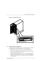
Page 18: ...ree standing storage enclosure that is com pletely self contained It has two fan cooled power supplies an internal EMU circuit board and a RAID array controller with front panel display and control Figure 1 2 shows the major components in the pedestal enclosure Figure 1 3 identifies the items on the rear panel power supplies The character istics of the pedestal cabinet are outlined below The disk ...

Page 19: ...Chapter 1 Product Overview EK SMCPO UG A01 1 5 Figure 1 2 Pedestal Front Panel Major Components Figure 1 3 Pedestal Rear Panel Power Supplies ...

Page 20: ...s the controllers support fully automatic and smooth controller failover The controller supports one or two standard 72 pin cache SIMMs of up to 64 MB In a redundant controller setup both controllers must have identical cache configurations and the total usable cache per controller will be half the amount installed Thus in a single controller setup the maximum usable cache is 128 MB while a redund...

Page 21: ...m problems associated with poor quality AC power or a complete loss of AC power The UPS is connected between the AC outlet and the line input of the pedestal power supply B to provide battery backup power The major features of the UPS include Cell Saver Technology doubles battery life and speeds recharge time hot swap batteries and network surge protection The front panel display has user controls...

Page 22: ...ty of exchanging signals with auxiliary devices and controllers The EMU is located internally in the top rear of the pedestal as shown in Figure 1 4 It is connected to the SCSI bus and powered by an internal cable The fol lowing external components on the rear panel of the pedestal are part of the EMU see Figure 1 5 An alarm switch S1 that enables up or disables down the audible alarm A power moni...

Page 23: ...figured as a split bus that connects the controller s to the disk drives The split bus arrangement is divided into two bus paths designated device port 0 and device port 1 as shown in Figure 1 6 Port 0 connects the controller to the upper four devices in the pedestal IDs 8 through 11 and port 1 connects the controller to lower three devices IDs 8 through 10 The device addresses on the bus are set ...

Page 24: ...ific position the switch controls the addresses of each SBB slot Figure 1 8 identifies the pedestal slot locations and their corresponding SCSI ID addresses for each device port The subsystem can be reconfigured for through bus operation by modifying the bus and resetting the internal configuration switch The information needed to reconfigure the bus from split bus to a through bus configuration i...

Page 25: ...MCPO UG A01 1 11 Figure 1 7 UltraSCSI Bus Configuration Switch 3000 38 6 Figure 1 8 Slot Locations and SCSI ID Addresses SLOT 0 SLOT 1 SLOT 2 SLOT 3 SLOT 4 SLOT 5 SLOT 6 ID 8 Controller Device Port 0 Device Port 1 ID 10 11 8 3000 52 ...

Page 26: ...olutions software kit Host interface UltraSCSI wide differential Drive interface UltraSCSI wide single ended RAID levels supported 0 1 0 1 4 5 Non RAID disk support Yes JBOD Sustained I O rate 4 400 I O s per second per controller pair RAID 5 sustained transfer rate 28 MB per second per controller pair Maximum transfer rate 40 MB per second per controller pair Redundant fans Yes Redundant power su...

Page 27: ...er Specifications Item Rating Input power 110 240 Vac 50 60 Hz single phase 12A 6A Heat dissipation 3070 BTUs hr Temperature optimal minimum required 18 to 24 C 10 to 40 C Altitude Up to 2 400 m Air quality Not to exceed 500 000 parti cles ft3 for air at a size of 0 5 micron or larger Total power per power supply Total of 12 Vdc and 5 Vdc outputs 204 Watts maximum Nominal output voltages 5 Vdc 15 ...

Page 28: ......

Page 29: ... unit is configured with two Ultra Wide differential SCSI host channels ca pable of transferring data to and from the host at rates up to 40 MB s The host SCSI IDs are configurable via the Host Parameters and can support 32 deep tagged queuing The controller is also configured with two Ultra Wide single ended SCSI disk channels capable of transferring data to and from the disk drives at rates up t...

Page 30: ...ive and and the other controller is in a standby passive mode Re dundancy Groups Virtual LUNS can be mapped to either SCSI host port or to both as in the single controller model In both cases a single controller failure will not affect the subsystem because the surviving controller will take over 2 2 Controller Features The controller is the intelligent bridge between the host and the devices in t...

Page 31: ... it provides the ability to combine several ordinary disk drives into a single high performance storage unit called a storageset Storagesets are implementations of RAID tech nology also known as a Redundant Array of Independent Disks Every storag eset shares one important feature whether it uses two disk drives or 14 each storageset looks like a single storage unit to the host You create storage u...

Page 32: ...ications Item Specifications Environmental Monitoring High Availability Fault Bus support via EMU Processor 40 MHz 32 bit LR33310 RISC CPU System Bus Interface Two WIDE Differential UltraSCSI channels Configuration Two RS232 serial ports RAID Levels Supported 0 1 0 1 4 5 Drive Channels Supported Two WIDE UltraSCSI single ended channels Number of Logical Drives LUN s Up to 30 RAID sets and up to 16...

Page 33: ...rt Yes Mixed Drive Types Yes Configurable Reconstruct Time Yes Stripe Size chunk size Variable Write through Cache Yes User Selectable default Write Back Cache Yes User Selectable optional Write on Top Yes Write Gathering Yes Battery Backup for Cache Yes Pedestal Uninterruptable Power Supply UPS Boot Capability Bootable from RAID set System dependent Number of Controllers System Two Cache Support ...

Page 34: ...cate that the controller is operating normally LEDs 1 through 4 display host and disk channel activity amber LED 5 normally off comes on red during a controller failure The LED Reset switch interface is de fined in Table 2 2 Table 2 2 LED Reset Switch Interface LED Name 0 Heart Beat Controller Reset Switch green 1 Host Channel 0 Activity LED amber 2 Host Channel 1 Activity LED amber 3 Disk Channel...

Page 35: ...ID sets in several different ways RAID sets can comprise drives from any drive channel and SCSI ID A RAID set can contain all the drives connected to the controller a single drive or any number of drives in between The controller supports RAID Levels 0 1 0 1 4 and 5 It also supports JBOD Just a Bunch of Drives allowing you to connect standalone disk drives such as a system disk to the controller w...

Page 36: ...mance and reliability the controller s core functions have been encapsulated in four custom ASIC Application Specific Integrated Circuits components as follows XOR ASIC Used in the Exclusive Or parity calculations employed by RAID levels 4 and 5 DMA ASIC Controls the data path hardware for the various I O ports CPU Interface ASIC Supports the controller s MIPS R3000 RISC central processing unit Me...

Page 37: ... room for other data or to prepare for a shutdown Write back caching makes the host more responsive to the user since the host does not have to wait for a lengthy RAID write before proceeding to another task 2 5 2 2 Write Gathering The controller will attempt to consolidate multiple writes destined for contiguous blocks and then write the entire data block in one operation The controller stores th...

Page 38: ...y drive JBOD Just a Bunch of Drives NOTE The controller stripes data in multi block chunk sizes Also the controller does not support RAID level 3 or 0 with a one block chunk size There are some restrictions you must adhere to when creating a RAID set on the RAID 3000 pedestal The minimum and maximum number of drives required to support each RAID level is listed in Table 2 4 Table 2 4 Pedestal RAID...

Page 39: ...unks the controller can use multiple drive channels to write the chunks to the disk drives Furthermore RAID 0 involves no parity calcula tions to complicate the write operation Likewise a RAID 0 read operation em ploys multiple drives to assemble a single large data block This makes RAID 0 ideal for applications such as graphics video and imaging that involve the writ ing and reading of large sequ...

Page 40: ...RAID Array 3000 Pedestal Enclosure 2 12 EK SMCPO UG A01 Figure 2 4 RAID 0 Write ...

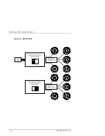
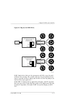
Page 41: ...5 illustrates a RAID 1 write Figure 2 5 Diagram of a RAID 1 Write A RAID 1 array will show up on the monitor as degraded when at least one drive fails even if two or more members of the redundancy group remain in good working order As long as at least two working drives remain in the array you may continue to run the array in degraded mode without putting data in jeopardy 2 6 3 RAID 0 1 RAID 0 1 c...

Page 42: ... ID Then it stripes the data across every other drive and forms a mirrored pair with the first two drives another mirrored pair with the second two drives and so on Table 2 5 describes how the controller uses the drives in a RAID 0 1 set Table 2 5 RAID 0 1 Example Drives Selected Function Channel 1 ID 0 First member of stripe set Channel 1 ID 1 Mirror of channel 1 ID 0 Channel 1 ID 2 Second member...

Page 43: ...lusive or on the chunks and then writes the chunks to all but one drive in the array and the parity data to the last drive When the host requests data from the disk drives the controller retrieves the chunks containing the addressed data re constitutes the data from the chunks and passes the data to the host Figure 2 7 Diagram of a RAID 4 Write ...

Page 44: ...any small I O operations scattered randomly and widely across the disks in the array RAID 4 s fixed par ity disk becomes a bottleneck in such applications as the following example il lustrates Let s say the host instructs the controller to make two small writes The writes are widely scattered involving two different stripes and different disk drives Ideally you would like both writes to take place...

Page 45: ...ller either uses the parity information on a stripe to reconstruct its data or simply reads the data as normal depending on the location of the stripe s parity drive While RAID 5 is ideally suited for applications with many small I O operations there is no reason why it cannot function equally well for applications with large sequential I O operations This makes RAID 5 an excellent all purpose RAI...

Page 46: ...JBOD disk drive is not part of a redundancy group even though the controller assigns a redundancy group num ber to the drive This number becomes that logical unit number LUN that the host will use to address the drive One use for JBOD is to connect a system disk drive to the controller The drive does not become part of a RAID set but it is made available to the host on the same SCSI bus as the oth...

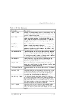
Page 47: ...elies on spatial locality Read Ahead Limit Limits the amount of cache blocks that will be read ahead when read ahead is enabled This limit prevents the cache from being dominated by read ahead data Validation Delay Determines how long the controller will delay after spinning up drives before scanning them The larger the number the more time the drives have to initialize themselves 12 Volt Sensor E...

Page 48: ...stent configurations including identical memory cache and system parameters If the controller setups are incompatible the set is not bound and each controller operates in stand alone mode 2 8 2 Message Passing Information is shared between the two controllers by a collection of messages passed through the backplane connectors The messages provide configuration data as well as a heartbeat which is ...

Page 49: ...ower If no backup power supply is provided the control ler will remain off line and reject all I O requests with a status of Check Condi tion Hardware Error If the backup power source indicates that power may be failing the controller s first step is to sound an alarm enter write through mode and begin flushing cache If the backup power source reaches a critical state the alarm frequency increases...

Page 50: ... 2 9 2 1 System Voltage The controller monitors the incoming system voltage levels and ensures they are satisfactory for controller operation The acceptable voltage levels are listed in Table 2 8 Table 2 8 Acceptable System Voltage Levels State Range Action Normal 4 80 5 25 V Normal Operation Low Warning 4 75 4 80 V Alarm High Warning 5 25 5 30 V Alarm Low Severe Less than 4 75 V Off line High Sev...

Page 51: ... Low Warning 4 00 4 20 V Alarm High Warning 5 40 5 55 V Alarm Low Severe Less than 4 00 V Off line High Severe Greater than 5 55 V Off line 2 9 2 3 12 V Supply Voltage The controller monitors the incoming 12 volt levels and ensures they are satisfac tory for operation The acceptable voltage levels are shown in Table 2 10 Table 2 10 Acceptable 12 Volt Levels State Range Action Normal 10 80 13 80 V ...

Page 52: ...ternal Temperature Voltage Levels State Temperature Action Normal 41º C Normal Operation High Warning 41º C 52º C Alarm High Severe 52º C Off line 2 9 3 2 Board Temperature The controller monitors the on board operating temperature and ensures they are satisfactory for controller operation The acceptable temperature levels are shown in the following table Table 2 12 Acceptable Board Temperature Vo...

Page 53: ...oubleshooting the pedestal consists of monitoring the status of the external LEDs to determine if a major component is malfunctioning The Field Replace able Units FRUs in the pedestal are Disk drives SBBs RAID array controller Power supplies Environmental Monitor Unit EMU circuit board Uninterruptable Power Supply UPS The information in this chapter is divided into the following major sections Ped...

Page 54: ... the green power LED is on and the am ber pedestal fault LED is off Also the green power supply LED on the rear of each power supply is on Figure 3 1 Pedestal Status LEDs 3 3 SBB Status LEDs Each disk drive SBB in the pedestal has two status LEDs a green activity LED and an amber fault LED as shown in Figure 3 2 When the pedestal is operating properly the activity LED is flashing indicating normal...

Page 55: ...nactive and not spinning Rec ommend that you replace the device On Flashing Fault status drive is active and slowing down due to the fault Figure 3 2 Disk Drive Status LEDs 3 4 Controller LEDs The LEDs on the front panel of the controller monitor host and disk channel ac tivity and a controller fault condition The reset button LED flashes green ap proximately once every second heartbeat to indicat...

Page 56: ...alfunctions using an audible alarm and a LED The user enabled audible alarm and the amber fault LED on the front of the pedestal are the only error indicators Whenever any of the following error conditions occur the amber fault LED on the front of the pedestal will turn on When alarm switch S1 on the rear panel of the pedestal is in the up enabled position the audible alarm will sound when ever on...

Page 57: ...supply Replacing the controller Replacing the EMU board Replacing the UPS Replacing a controller memory cache module 3 6 1 Removing the Pedestal Door Proceed as follows to remove the pedestal door Figure 3 3 1 Unlock and open the door to a 90º angle in relation to the pedestal 2 Carefully lift up on the door until the hinge pins are against the top of the mounting holes 3 Pull the door straight ou...

Page 58: ...se both hands when removing or in serting an SBB Never remove a drive from the pedestal be fore it has completely spun down Take care not to slam the replacement SBB into the pedestal enclosure 1 Unlock and open the front door 2 Release the drive from the pedestal slot by squeezing the mounting tabs on the SBB together but do not remove the SBB from the pedestal 3 Wait 15 30 seconds for the drive ...

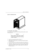
Page 59: ...ly as quickly as possible to prevent overheating 1 Grasp the power supply handle shown in Figure 3 5 2 Slide and hold the locking latch to the left and pull the supply out using a short jerking motion 3 Insert the replacement power supply into the pedestal and carefully align it 4 Push the power supply in until it is fully seated and the locking tab engages 5 Until the fan is operating at the prop...

Page 60: ...RAID Array 3000 Pedestal Enclosure 3 8 EK SMCPO UG A01 Figure 3 5 Replacing a Power Supply ...

Page 61: ...l the controller disengages from its mounting slot 2 Remove the controller by sliding it forward and free of the pedestal 3 Insert the replacement controller into the open slot align the module into the card guides and gently slide it into the pedestal until the connector engages the backplane connector in the pedestal 4 Turn the two front panel latches inward to fully seat the controller in the p...

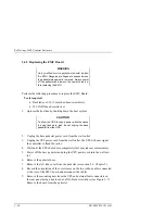
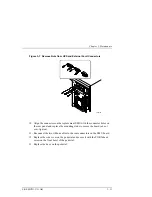
Page 62: ...k do not unplug the base pedestal from the UPS 2 Unplug the base pedestal power cord from the wall outlet 3 Unplug the UPS power cord from the wall outlet the UPS will now signal the controller to flush the cache 4 Wait until the UPS shuts down completely this may take several minutes 5 Power off the base pedestal and plug the UPS power cord into the wall out let 6 Remove the pedestal door 7 Remov...

Page 63: ...cement EMU with the connector holes on the rear panel and replace the mounting studs to secure the board do not over tighten 11 Reconnect the two ribbon cables to the rear connectors on the EMU board 12 Replace the side cover on the pedestal and secure it with the TORX head screw on the front bezel of the pedestal 13 Replace the door on the pedestal ...

Page 64: ...llowing factors The bus transmission rate The maximum SCSI bus length a function of bus type the transmission rate and the use of SCSI bus converters The total length of the SCSI bus as measured from the host bus terminator to the subsystem terminator MT s mega transfers per second is the repetitive rate at which words of data are transferred across a bus The number of megabytes per second MB s is...

Page 65: ... the de vice addresses for each bus and their corresponding pedestal slot location Table 3 3 Assigned Slot Device Addresses in the Pedestal Slot 0 1 2 3 4 5 6 Bus D0 D1 Device Address 8 9 10 11 8 9 10 3 7 1 Reconfiguring the SCSI Bus WARNING Only qualified service personnel should reconfig ure the SCSI bus Dangerous voltages are present within the subsystem To prevent electrical shock always turn ...

Page 66: ...ows a maximum of 15 or 14 with dual controllers disk devices on each of its device buses To remove the side panel proceed as follows 1 Quiesce the host bus by shutting down the host system CAUTION To allow the UPS to supply power while the cache is being flushed to disk do not unplug the base pedestal from the UPS 2 Unplug the base pedestal power cord from the wall outlet 3 Unplug the UPS power co...

Page 67: ...nfiguration number Press the lower switch to step the address up one address at a time increment until the desired configuration number is displayed 9 Figure 3 9 shows the location of the switch Figure 3 10 depicts the separate step switches to set the subsystem to the desired SCSI bus configuration refer to the label at bottom of pedestal to cross reference slot SCSI ID ad dresses with switch set...

Page 68: ...UG A01 Figure 3 9 Location of SCSI Bus Configuration Switch 3000 38 6 Figure 3 10 Configuration Switch 6 NOTE Reconfiguring the bus also involves cable and bus terminator changes Chapter 4 of this guide de scribes in detail how to reconfigure the bus ...

Page 69: ... wear an ESD wrist strap con nected to a suitable ground when handling the memory chips 1 Power down the pedestal first and then the UPS 2 Grasp the latches on the front of the controller and pull them forward until the con troller disengages from the pedestal see Figure 3 11 3 Remove the controller from the pedestal and place on a flat working surface 4 Remove the two installed cache memory SIMM ...

Page 70: ...sure 3 18 EK SMCPO UG A01 Figure 3 12 Release Locking Clips Figure 3 13 Remove Installed SIMM Modules CAUTION Ensure the side 1 side of the two replacement SIMMs is facing toward you when installing the modules in the following step ...

Page 71: ...ivot the mod ule the main controller board until it snaps into place see Figures 3 14 and 3 15 6 Replace the controller into the pedestal 7 Power on the UPS and pedestal and check the activity LEDs on the front panel of the controller The reset switch LED should begin to flash at a half second rate heartbeat and the host activity LEDs should flash Figure 3 14 Install Replacement Modules ...

Page 72: ...RAID Array 3000 Pedestal Enclosure 3 20 EK SMCPO UG A01 Figure 3 15 Pivot Module Down to Secure ...

Page 73: ...o expand the storage capacity of the RAID Array 3000 subsystem When connected to the RAID Array 3000 base pedestal the expansion option contains the basic compo nents required to create a dual pedestal storage array with a 16 bit single ended Ultra SCSI bus The option enables a user to add up to seven 3 inch SBBs to create a 14 device storage array The expanded array is controlled and operated in ...

Page 74: ...racter istics of the expansion pedestal cabinet are outlined below The storage device capacity of the expansion pedestal is seven 3 inch SBBs The pedestal slots are numbered 0 through 6 from top to bottom There are seven SCSI bus device addresses target IDs 8 through 14 which can be assigned to the 3 inch SBBs There is a single 68 pin VHDC female SCSI connector on the rear panel which interconnect...

Page 75: ...apter 4 Expansion Pedestal Option EK SMCPO UG A01 4 3 Figure 4 2 Expansion Pedestal Slot Locations and ID Addresses 300 0 19A EXPANSION PEDESTAL SLOT 6 SLOT 5 SLOT 4 SLOT 3 SLOT 2 SLOT 1 SLOT 0 ID 8 ID 14 ...

Page 76: ...onfigured as one continuous bus that runs along the backplane between the disk drive connectors and the internal ca bles These cables connect the drives to the connectors located on the rear panel of the expansion pedestal The device addresses on the bus are set at the factory by an internal configuration switch When set to a specific position the switch controls the addresses of each SBB slot The...

Page 77: ... external components on the rear panel of the expansion pedestal are part of the EMU board The alarm switch S1 that enables up or disables down the audible alarm The External Fault Condition connector allows the EMU to monitor the status of a user selected device Figure 4 4 EMU Circuit Board Location 3000 37 EM U 4 4 Reconfiguring Base Pedestal UltraSCSI Bus WARNING Only qualified service personne...

Page 78: ...ing procedure to reconfigure the SCSI bus in the base pedestal from a split bus to a through bus configuration 1 Perform an inventory of the bus conversion items supplied with the pedestal expansion kit option The items should consist of SCSI bus jumper cable 17 04166 03 SCSI cable 17 04454 01 2 Quiesce the host bus by shutting down the host system CAUTION To allow the UPS to supply power while th...

Page 79: ... 4 5 Remove Side Cover from Base Pedestal 8 Remove the bus terminator from backplane connector J11 Figure 4 6 Figure 4 6 Remove SCSI Bus Terminator 3000 40 Remove Terminator 9 Remove the SCSI cable from device 1 connector and backplane connector J16 see Figure 4 7 ...

Page 80: ... A01 Figure 4 7 Disconnect SCSI Cable 3000 41 Remove SCS I Cable 10 Connect jumper cable 17 04166 03 between the backplane connector J11 and the backplane connector J16 see Figure 4 8 Figure 4 8 Connect SCSI Jumper 3000 42 Connect Jumper Cable J11 J16 ...

Page 81: ...e rear panel of the base pedestal see Figure 4 9 Figure 4 9 Remove Connector Knockout Plate 3000 45 Remove Knockout from D1 O ut 12 Connect cable assembly 17 04454 01 between the D1 OUT bulkhead open ing and the device 1 backplane connector see Figure 4 10 Secure the bulkhead connector by tightening the two 6 32 SEM screws ...

Page 82: ...igure 4 10 Connect SCSI Cable 3000 43 Connect S CS I Ca ble 13 Set the bus configuration switch to 7 see Figures 4 11 and 4 12 Figure 4 13 shows the reconfigured SCSI bus addresses of the expanded subsystem Figure 4 11 Set Configuration Switch to 7 3000 44 7 ...

Page 83: ...Chapter 4 Expansion Pedestal Option EK SMCPO UG A01 4 11 Figure 4 12 Configuration Switch Figure 4 13 Reconfigured SCSI Bus Addresses ...

Page 84: ...able from the D1 OUT connector on the base pedestal to the D1 IN connector on the rear of the expansion pedestal as shown in Figure 4 14 Figure 4 14 Connect SCSI Cable Between Pedestals 3000 47 Base Pedestal Expansion Pedestal 16 Make the power cable connections between the expansion pedestal the UPS and the ac power source see Figure 4 15 ...

Page 85: ...Power CAUTION If you want to maintain the existing RAID level con figuration three drives must be relocated from the base pedestal to specific slots in the expansion pedestal as described in step 13 17 Transfer the bottom three disk drives slots 4 5 and 6 from the base pedestal to the top three slot locations slots 0 1 and 2 in the expansion pedestal as shown in Figure 4 16 ...

Page 86: ...13 ID 14 Expansion Pedestal 3000 46 ID 8 ID 9 ID 10 ID 11 ID 8 ID 9 ID 10 Base Pedestal 18 Install the new drives in the remaining slots each pedestal to complete the installation 19 Power up the UPS and the two pedestals and then proceed to StorageWorks RAID 3000 Configuration and Maintenance Guide EK SMCS2 UG to con figure the expanded subsystem ...

Page 87: ...he installation procedure consists of adding two SIMM memory modules to the redundant controller and one memory module to the existing controller in the pedestal Following the memory upgrade you simply insert and seat the devices in their respective controller slots and configure the subsystem to accommodate a redundant controller The following steps summarize the option installation pro cedure En...

Page 88: ...o prevent an electrical discharge from damaging the SIMMs always wear an ESD wrist strap con nected to a suitable ground when handling the memory modules 1 Ensure that the UltraSCSI bus is in a quiescent state no I O activity 2 Shut down the host system 3 Issue a shutdown command from the SWCC console to the pedestal con troller 4 Power off the pedestal s and the UPS ...

Page 89: ...rranty Card 6 Install two of the SIMM modules into the second controller make sure all modules are of the same type by aligning the connector pins and inserting the modules into the SIMM module connectors as shown in Figure 5 2 Figure 5 2 Insert Module into SIMM Connector 7 Ensure the module is firmly seated and then gently pivot it toward the con troller board until it snaps into place as shown i...

Page 90: ...SMCPO UG A01 Figure 5 3 Pivot Module Down to Seat 8 Remove the existing controller see Figure 5 4 and install the third module into the empty SIMM connector using the same procedure described in step 6 Figure 5 4 Remove Controller from Top Slot ...

Page 91: ...er align with the guides in the slot 10 Remove the dummy filler panel from the bottom controller slot by pulling the handle straight out 11 Install the second controller into the bottom controller slot and seat it into place by pushing forward on the side quick disconnect handles 12 Power up the subsystem and refer to the RAID Array 3000 configuration and maintenance guide EK SMCS2 UG for informat...

Page 92: ......

Page 93: ...ditional sheets if needed Thank you Manual Rating Excellent Good Fair Poor Accuracy correct presentation of facts Completeness adequate information Clarity easy to understand Organization logical sequence of information Layout easy to follow subject matter Indexing easy to locate desired information Errors Noted please include page paragraph table or figure number Return Address Customer Research ...

Page 94: ......

Reviews: