background image

18

filter cover on top of filter pan and slide the
filter back inside the fryer.

j.   Reconnect oil  return quick disconnect lines

(if installed on the fryer).

9.3 FILTER OPERATION:

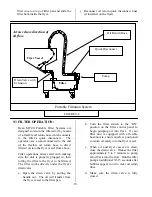
Dean MF-90 Portable Filter Systems are
designed to return the filtered oil by means
of a flexible oil return hose which connects
to the filter’s quick disconnect.  The
operator uses a wand connected to the end
of the flexible oil return hose to direct
filtered oil into the fryer vessel from above.

Filter operations always start with making
sure the unit is properly plugged in, then
rolling the filter to the fryer to be filtered.
The filter works directly under the fryer's
drain valve.

a. Open the drain valve by pulling the

handle out.  The oil will transfer from
the fryer vessel to the filter pan.

b. Turn the filter switch to the “ON”

position on the filter control panel to
begin pumping oil into fryer.  If your
filter unit is equipped with a flexible
hose/nozzle, ensure nozzle is positioned
to return oil safely into the fryer vessel.

c. When oil and fryer vessel are clean,

close the drain valve.  It takes the filter
approximately 5 to 7 minutes to pump
all oil back into the fryer.  Run the filter
pump an additional 10-15 seconds after
bubbles appear in oil to clear oil return
lines.

d. Make sure the drain valve is fully

closed.

Oil Return Hose

Fryer Vessel

Filter

Pump

Drain Valve with
Extension

Quick Disconnect

Arrows show direction of
oil flow.

Portable Filtration System

FIGURE 9-2

Summary of Contents for Electric Fryer

Page 1: ...ial Food Equipment Service Association recommends using CFESA Certified Technicians Price 6 00 24 Hour Service Hotline 1 800 551 8633 819 5709 04 99 Super Runner 38 Series Electric Fryers CE Installat...

Page 2: ...STALLATION INSTALLATION MUST BE PLANNED IN ACCORDANCE WITH ALL APPLICABLE STATE AND LOCAL CODES OR IN THE ABSENCE OF LOCAL CODES WITH THE NATIONAL ELECTRICAL CODE NFPA 70 1984 OR LATEST EDITIONS WARNI...

Page 3: ...ver of this booklet To speed up your order the following information is required Model Number Serial Number Type of Voltage Item Part Number Quantity Needed 1 2 SERVICE INFORMATION Call the Dean Facto...

Page 4: ...ermostat The temperature control is mounted in the cabinet behind the front door on the bottom left side of the cabinet d AUTOMATIC SAFETY FEATURE High temperature detection to shut off electric heate...

Page 5: ...e all accessories from the carton Do not discard or misplace these as they will be needed After unpacking immediately check the equipment for visible signs of shipping damage If such damage has occurr...

Page 6: ...asters are installed to ensure the fryer is level before using b Leg Installation 1 Remove unit from pallet 2 Carefully raise unit with forklift pallet jack or other steady means 3 Insert hex head bol...

Page 7: ...m 1 1 16 open end wrench by turning the hex bullet on the bottom of the leg See figure 3 2 on page 7 3 The hex bullet is for minor leg height adjustment only Do not adjust more than 22mm 1 4 When leve...

Page 8: ...f installation to ensure it meets the intent of these instructions The on site supervisor and or operator s should be made aware that there is a restraint on the appliance and if disconnection of the...

Page 9: ...that the heaters and thermostat operate properly drain the vessel of water and dry thoroughly Refill fry vessel with shortening as directed in section 3 6 Final Preparation 3 6 FINAL PREPARATION a Whe...

Page 10: ...L POWER SERVICE IS DISRUPTED FOR MORE THAN A FEW SECONDS TURN FRYER OFF THIS WILL PREVENT THE FRYER FROM ACCIDENTALLY HEATING OIL WHEN POWER SERVICE IS RESUMED WARNING IF USING SOLID SHORTENING NEVER...

Page 11: ...he food being prepared minimizes flavors being transferred from batch to batch and increases frying compound lifespan Filter the frying compound at least once daily or more frequently if cooking is he...

Page 12: ...oth front casters locking mechanisms have to be turned OFF To return the unit to its previous installed position see sections 3 4 and 5 3 of this manual 5 4 WEEKLY a Completely drain the oil from the...

Page 13: ...ned for this material at the end of each day a Do not use steel wool abrasive cloths cleansers or powders b Do not use a metal knife spatula or any other metal tool to scrape stainless steel Scratches...

Page 14: ...operating position It should be clamped to the 2nd element with 1 5 mm 1 16 inch spacing See Figure 6 2 2 Place the sensing bulb of a high quality immersion thermometer about 38 mm 1 1 2 inches above...

Page 15: ...P N 1549 BLK 2 WHT 2 PURP RED Oper Thermostat P N 2557 Hi Limit P N 2687 PURP RED BLU YEL WHT 2 BLK 2 YEL BRN Transformer P N 807 1999 240V 24V YEL YEL BLU BRN Power Switch SPST P N 807 2196 YEL K2 K1...

Page 16: ...2686 CASTER RIGID 3 44 1363 NIPPLE DRAIN EXT 1 1 4 12183 2 DOOR ASSY SS SR38 12 0308 2 DOOR PANEL SS SR38 12 0097 DOOR PIN 1503 MAGNETIC DOOR CATCH 4 1039 2 HANDLE CHROME DOOR 5 9002949 SHIM CASTER 6...

Page 17: ...E 25 12185 1 VESSEL MS WELD ASSY SR38E 14 0592 8 HEAT ELEMENT 220V 4000W 380 400 415 240 USA 14 3KW 26 14 0592 7 HEAT ELEMENT 208V 4666W USA 14KW 1902 O RING SEAL 4 EA ELEMENT 14 0695 O RING RETAINER...

Page 18: ...le lines up to drain Solid shortening will solidify as it cools and clog the lines 9 2 FILTER PREPARATION a Turn the fryer OFF b Remove the filter pan cover c Remove the crumb screen if provided and c...

Page 19: ...y under the fryer s drain valve a Open the drain valve by pulling the handle out The oil will transfer from the fryer vessel to the filter pan b Turn the filter switch to the ON position on the filter...

Page 20: ...op of the new sheet It is essential that two sheets of Dean filter papers are used use of other than OEM parts will void the filter warranty g Replace the hold down ring and latch into position Sprink...

Page 21: ...the flex hose valve Go to page 22 Yes No Yes No No it Yes Yes No Insert flexible oil return hose into the filter pan holster Turn pump motor ON Disconnect flexible oil return hose Make sure it is coo...

Page 22: ...rs by latching the hold down ring Sprinkle 45kg 16oz of filter powder evenly across the surface of the filter paper Check the filter sump Sediment collects around the suction pipe in the filter bottom...

Page 23: ...ntinue Pump motor is clogged or faulty Contact your local Factory Authorized Service Center Check filter circuit breaker Push the circuit breaker reset button Verify power cord is connected to the out...

Page 24: ...in hot water until you can blow through it The line is clear Reconnect hose to the pump inlet Does oil flow Conduct normal filter operations There may be a plug in the bottom of the filter pan Take f...

Page 25: ...n 8700 Line Avenue Shreveport Louisiana 71135 TEL 1 318 865 1711 FAX Parts 1 318 219 7140 Tech Support 1 318 219 7135 Price 6 00 PRINTED IN THE UNITED STATES SERVICE HOTLINE 1 800 551 8633 819 5709 04...

Reviews: