background image

TABLE OF CONTENTS

1.  DESCRIPTION AND  SPECIFICATIONS

.....................................................

1

2.  PRE-INSTALLATION

......................................................................................

2

3.  RECEIVING AND INSTALLING THE FRYER

............................................

2

4.  INITIAL START-UP

.........................................................................................

3

5.  DAILY OPERATION

........................................................................................

4

6.  CLEANING & MAINTENANCE

.....................................................................

5

7.  TROUBLESHOOTING

.....................................................................................

6

8.  RECOMMENDED SPARE PARTS/PARTS LIST 

.........................................

7

9.  FACTORY SERVICE & PARTS ORDERING

..............................................

11

10.   SPECIFICATIONS

......................................................................................

12

11.  WIRING  DIAGRAMS

..................................................................................

13

LIMITED WARRANTY

.......................................................................................

17

Summary of Contents for 1414E

Page 1: ... Food Equipment Service Association recommends using CFESA Certified Technicians Price 6 00 24 Hour Service Hotline 1 800 551 8633 819 5867 Cool Zone Series Electric Fryers Installation Operation Manual Models 714E 1414E 1818E 2020E ...

Page 2: ... INFORMATION SHALL BE OBTAINED BY CONTACTING THE LOCAL GAS COMPANY OR GAS SUPPLIER FOR YOUR SAFETY DO NOT STORE OR USE GASOLINE OR OTHER FLAMMABLE VAPORS AND LIQUIDS IN THE VICINITY OF THIS OR ANY OTHER GAS APPLIANCE IMPORTANT SAFE AND SATISFACTORY OPERATION OF YOUR EQUIPMENT DEPENDS ON IT S PROPER INSTALLATION INSTALLATION MUST BE PLANNED IN ACCORDANCE WITH ALL APPLICABLE STATE AND LOCAL CODES WA...

Page 3: ...TION 2 3 RECEIVING AND INSTALLING THE FRYER 2 4 INITIAL START UP 3 5 DAILY OPERATION 4 6 CLEANING MAINTENANCE 5 7 TROUBLESHOOTING 6 8 RECOMMENDED SPARE PARTS PARTS LIST 7 9 FACTORY SERVICE PARTS ORDERING 11 10 SPECIFICATIONS 12 11 WIRING DIAGRAMS 13 LIMITED WARRANTY 17 ...

Page 4: ...ermostat or an optional solid state temperature controller Either temperature control is mounted in the cabinet behind the front door on or near the cabinet floor Optional panel mounted main power switch rocker type reset switch melt cycle switch and instant power switch are mounted on control panel Melt Cycle This feature pulses the heating elements on and off at a controlled rate This should be ...

Page 5: ...G INSTALLING THE FRYER UNPACKING Check that the container is upright Use outward prying no hammering to remove the carton Check the fryer s for visible damage if such damage has occurred do not refuse shipment but contact the carrier and file the appropriate freight claims Do not contact the factory as the responsibility for shipping damage is between the shipper and the dealer or end user Remove ...

Page 6: ... for food preparation then rinsed out and wiped dry Wash also any accessories shipped with the unit Close the drain valve completely and remove the crumb screen Make sure the screws holding the thermostat and limit control sensing bulbs into the vessel are tight HEATING THE VESSEL Fill the fryer vessel with hot or cold water to the oil level line scribed into the back of the tank This step will ch...

Page 7: ...mpound Although 350 F is the usual temperature recommended for most cooking operations frying should be carried out at the lowest temperature which will produce a high quality and product while ensuring maximum life of the frying compound When the fryer is not in use the temperature controller or operating thermostat should be set lower than that used during cooking Light loads too may be cooked a...

Page 8: ...d more often than daily under heavy use d Do not run water through the filter as part of the cleaning process the filter pump is not designed to handle water This will void the warranty for your filter hasten filter pump failure and could cause accidents if water mixes with hot oil WEEKLY a Completely drain the fryer vessel into either the filter or a steel container Do not use a plastic bucket or...

Page 9: ...t actuated check continuity of the two holding coil circuits from the indicator light to L2 f If the panel indicator light is not glowing first check that line voltage does not exist across the lamp then 1 Check the fuse for line voltage between the load side and L2 2 Check the power on off switch for line voltage between the load side and L2 3 Check the high limit thermostat for line voltage betw...

Page 10: ...light in the power switch turns off and on within 10 F of that setting the probe is defective and must be replaced If the indicator light does not come on within 10 F call for service as the problem could be in the temperature controller b If the indicator light and heating elements do not come on at all but will when the probe test button is pushed and the thermostat dial is turned past 350 F the...

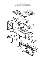
Page 11: ...8 PARTS LIST COOL ZONE ELECTRIC FRYERS MODELS 714E 1414E 1818E 2020E ...

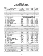
Page 12: ...74 18 Temperature sensor Robershaw Furnished With Thermostat Operating thermostat 2557 2557 2557 2557 Thermostat knob 1205 1 1205 1 1205 1 1205 1 19 High limit switch 1365 1365 1365 1365 20 High limit mounting bracket 07 0138 11 0171 18 0040 11 0171 21 Magnetic door catch 1503 1503 1503 1503 22 Canopy 07 0060 07 0034 24 0092 20 0014 23 Wireway front cover 07 0135 14 0617 18 0037 20 0056 24 Control...

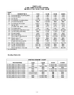
Page 13: ...0004 24 0004 48 Drain valve 1 07083 N A N A N A Drain valve 1 1 4 N A 2066 1 2066 1 2066 1 Optional mercury switch N A 1936 1936 1936 49 Drain Valve extension N A 14 0178 14 0178 14 0178 50 Lower structural back 07 0140 07 0026 N A N A 51 Upper structural back 07 0139 14 0424 N A N A Structural back one piece N A N A 24 0075 20 0057 Not Illustrated Heating Elements HEATING ELEMENT CHART DESCRIPTIO...

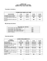
Page 14: ... switch red Carling instant power 2027 Rocker switch blk w o light melt cycle 2026 Switch hold plug 2048 Vessel Assemblies VESSEL REPLACEMENT KITS VESSEL DESCRIPTION 714E 1414E 1818E 2020E Mild Steel WIP 07078 3SK 14248 3SK 18024 3SK N A Stainless Steel WIP 07078 4SK 14248 4SK 18024 4SK 20028SK Mild Steel WIP with Computer N A 14290 3SK 18125 3SK N A Stainless Steel WIP with Computer N A 14290 4SK...

Page 15: ...ir Center or contact the factory direct Always give the model and serial number of your fryer ORDERING PARTS Customers may order parts directly from their local Authorized Parts Distributor For this address and phone number contact your Maintenance Repair Center or call the factory Factory address and phone numbers are on the cover of this booklet ...

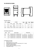
Page 16: ... 60Hz 1ph 33 3A N A N A 1414E 18 KW 208V 60Hz 1PH 86 5A 240V 60Hz 1ph 75 0A 208V 60Hz 3ph 50 0A 240V 60Hz 3ph 43 3A 1818E 13 5 KW 18 KW 208V 60Hz 1PH 65 0A 208V 60Hz 1PH 86 5A 240V 60Hz 1ph 56 3A 240V 60Hz 1ph 75 0A 208V 60Hz 3ph 37 5A 208V 60Hz 3ph 50 0A 240V 60Hz 3ph 32 5A 240V 60Hz 3ph 43 3A 2020E 13 5 KW 18 KW 208V 60Hz 1PH 65 0A 208V 60Hz 1PH 86 5A 240V 60Hz 1ph 56 3A 240V 60Hz 1ph 75 0A 208V...

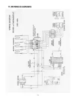
Page 17: ...14 11 WIRING DIAGRAMS ...

Page 18: ...15 ...

Page 19: ...16 ...

Page 20: ...17 ...

Page 21: ...ge FOB Authorized Distributor This warranty covers only the repair or replacement of the defective part and does not include any labor charges for the removal and installation of any part or travel or other expense incidental to the repair or replacement of a part Dean will not be responsible for problems found to be caused by use of a non OEM part or replacement of a defective part with other tha...

Page 22: ...Dean 8700 Line Avenue Shreveport Louisiana 71135 TEL 1 318 865 1711 FAX Parts 1 318 219 7140 Tech Support 1 318 219 7135 Price 6 00 PRINTED IN THE UNITED STATES SERVICE HOTLINE 1 800 551 8633 819 5867 ...

Reviews: