39
3
5
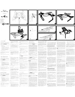
Your parts
1.
Top rotor arm cover
2.
Bottom rotor arm cover
3.
Snap ring
4.
Ring
5.
Grub screw M3 x 3mm
(spare)
6.
4 screws M3 x 10mm
7.
3 screws M2 x 6mm
1
Finished piece
The finished arm, with
the cover fitted, should
look like this. Keep
the arm in a safe place,
ready for the next
stage of assembly.
Back left arm
You fitted LED lights
to the back left arm
in Stage 12. Now take
the back left arm and
place it on your work
surface. Take the red
cover supplied with
this stage and fix it
into the socket of the
arm, as shown in the
pictures. Take care
not to squeeze or
bend the wires of
the LEDs.
2
1
Stage 17
Back left arm cover
In this stage, we fix the bottom red cover to the back left arm.
2
4
6
7
Assembly Guide
Summary of Contents for Sky Rider Drone
Page 1: ...Pack 04 TM www model space com ...
Page 11: ......


