background image

16

INSTALLATION INSTRUCTIONS

3


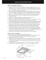
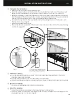
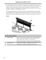
Temporarily insert the downdraft into the cabinet

With the assistance of another person, lift the downdraft unit into the prepared cutout 
in the cabinet. The over counter mounting brackets should rest on the countertop.

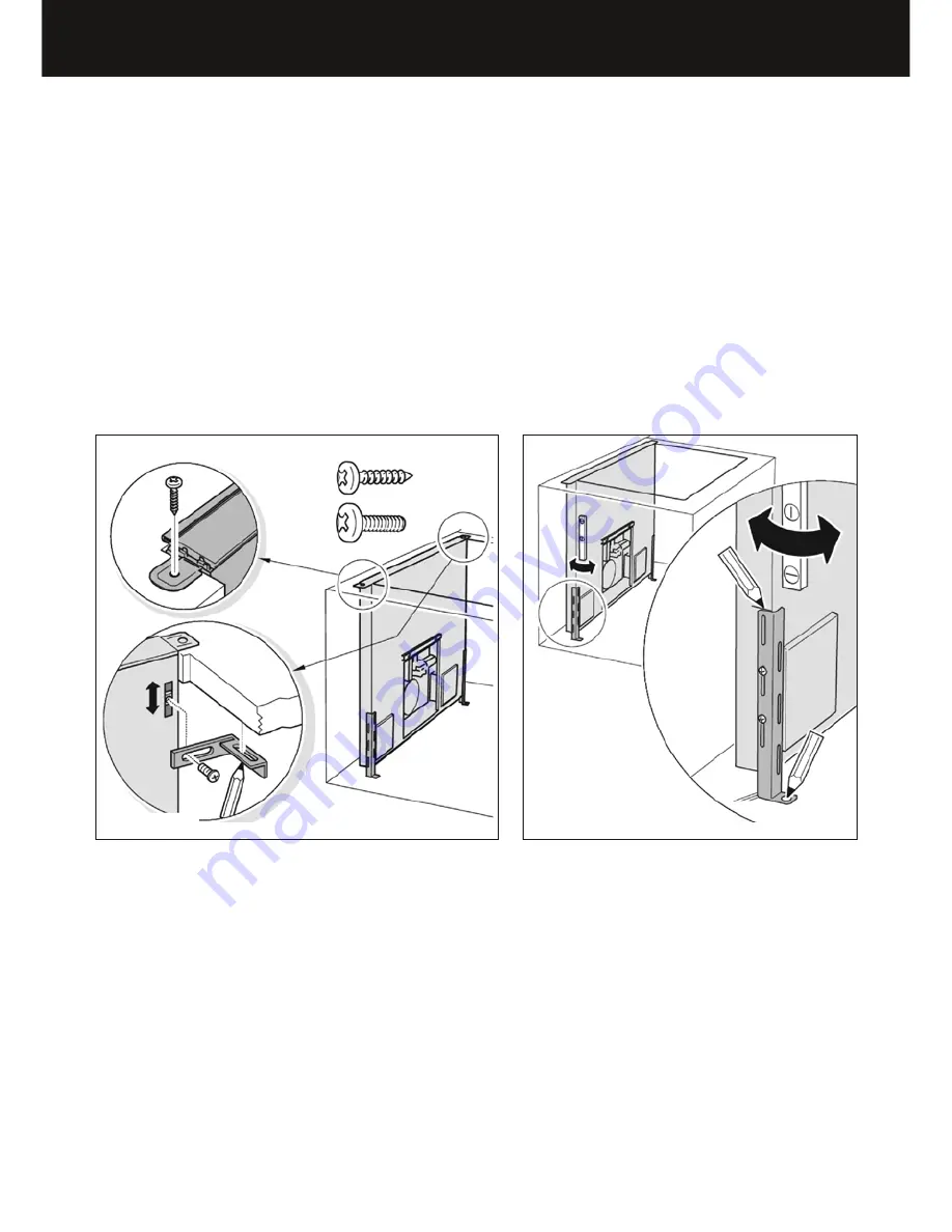
Secure the downdraft unit to the countertop with two 19/32” (15 mm) screws.

Install the under counter mounting brackets underneath the countertop for additional 
support. First, loosely screw the brackets into the sliding nuts in the downdraft 
unit using 3/16” (5 mm) screws and push them up under the countertop. Pre-drill 
the mounting holes into the countertop from underneath. Check that the mounting 
screws are the proper length and will not extend through the countertop surface 
when tightened. 

Failure to follow these instructions could result in damage to the 

countertop surface Fig.5.

Level and align the downdraft unit in the cabinet. Push the support leg mounting 
bracket on each side down against the cabinet floor. Mark the top edge of the 
mounting bracket on the downdraft unit and the mounting holes on the cabinet 
floor Fig.6.

4


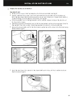
Remove the downdraft from the cabinet

Remove the screws from the countertop and lift the downdraft unit back out of 
the cabinet.

Pre-drill the marked mounting holes in the cabinet floor.

Tighten the support leg mounting brackets on the unit at the pre-marked positions

Place the downdraft unit on a flat protected surface to prevent damage in order to 
install the blower.

5


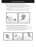
Install the internal or remote blower 

For internal blower installation refer to page 17.

For remote blower installation refer to page 19.
Note: this downdraft unit may only be used in connection with DCS internal or 
remote blowers.

2 x

2 x

Fig.5

Fig.6

Summary of Contents for HBD1200E

Page 1: ...NSTRUCTIONS D INSTALLATION GUIDE D UTILISATION INSTALLATION INSTRUCTIONS USER GUIDE Telescopic Downdraft Vent System Système de Ventilation Télescopique à Aspiration Descendante Modèles de systèmes de ventilation HD30 et HD36 Modèles de ventilateurs HBD600I et HBD1200E ...

Page 2: ...English Page 1 35 Français Page 37 71 ...

Page 3: ...SAVE THESE INSTRUCTIONS The models shown in this user guide may not be available in all markets and are subject to change at any time For current details about model and specification availability in your country please go to our website www dcsappliances com or contact your local DCS by Fisher Paykel dealer Registration Register your product with us so we can provide you with the best service pos...

Page 4: ......

Page 5: ...arise as you use your new appliance For your convenience product questions can be answered by a DCS Customer Care Representative by phone 1 888 936 7872 or email support dcsappliances com Note please write the Model Code and Serial Numbers on this page for references Vent Model Number________________ Code_________ Serial Number_______________ Blower Model Number______________ Code_________ Serial ...

Page 6: ...CTIONS READ THE ENTIRE SET OF INSTRUCTIONS BEFORE INSTALLING OR USING THIS APPLIANCE Manuals can also be found on our website www dcsappliances com CAUTION For general ventilating use only Do not use to exhaust hazardous or explosive materials and vapors WARNING To reduce the risk of fire electric shock or injury to persons observe the following Use this unit only in the manner intended by the man...

Page 7: ...ed at high settings Boilovers cause smoking and greasy spillovers that may ignite Heat oils slowly on low or medium settings Always turn hood ON when cooking at high heat or when flambéing food ie Crepes Suzette Cherries Jubilee Peppercorn Beef Flambé Clean ventilating fans frequently Grease should not be allowed to accumulate on fan or filter Use proper pan size Always use cookware appropriate fo...

Page 8: ...ducting and remote blowers should transition to 10 254 mm round duct as soon as possible If small ducting is used it should be transitioned to 10 254 mm round as soon as possible WARNING To reduce the risk of fire use only metal ductwork CAUTION To reduce risk of fire and to properly exhaust air be sure to duct air outside do not vent exhaust air into spaces within walls or ceilings or into attics...

Page 9: ... 1 2 12 7 mm conduit connector must be provided at each end of the power supply cable at the appliance and at the junction box When making the electrical connection cut a 11 4 32 mm hole in the wall A hole cut through wood must be sanded until smooth A hole through metal must have a grommet IMPORTANT Use this unit only in the manner intended by the manufacturer If you have any questions contact th...

Page 10: ...ease filter 2 Under counter mounting bracket 2 3 16 5 mm screw 2 5 16 8 mm screw 6 19 32 15 mm Self tapping screw 6 Top trim 1 HD30 and HD36 Vent models HBD600I and HBD1200E Blower models US CA INSTRUCTIONS D INSTALLATION GUIDE D UTILISATION INSTALLATION INSTRUCTIONS USER GUIDE Telescopic Downdraft Vent System Système de ventilation télescopique à aspiration descendante Modèles de systèmes de vent...

Page 11: ...LATION INSTRUCTIONS Internal blower HBD600I contents of packaging Internal blower box 1 6 152 mm diameter back draft damper 1 Remote blower HBD1200E contents of packaging Remote blower 1 Duct collar plate 1 EN ...

Page 12: ...the entire instructions before installing the downdraft vent system Remote blower connection plate can also be mounted on the back of appliance Ø10 254 mm 13 330 mm 13 330 mm 5 8 16 mm Downdraft unit and internal blower box HBD600I which can also be mounted on the back of the appliance 13 330 mm 13 330 mm 11 2 38 mm 3 8 9 5 mm 283 4 730 mm 21 8 54 mm 10 254 mm 6 152 mm diameter vent collar A C B F...

Page 13: ...ternal blower left right 6 152 mm ducting B Internal blower down 6 152 mm ducting C Internal blower rear 6 152 mm ducting D Remote blower power cord cutout down or to the rear E Remote blower rear 10 254 mm ducting F Cooktop overhang HD30 HD36 INSTALLATION DIMENSIONS inches mm inches mm G Minimum width of cooktop 28 711 34 864 H Downdraft cutout width 271 2 699 331 2 851 I Remote blower power cord...

Page 14: ...allation instructions for correct dimensions and clearances IMPORTANT Make certain any cooktop installed is appropriate for use with a downdraft vent system Venting requirements Attention should be given to ensure that any applicable regulations concerning the discharge of exhaust air are fulfilled For optimal efficiency use the shortest and straightest duct route possible and use rigid or semi ri...

Page 15: ...by adding the equivalent feet listed in the table below for each piece of duct in the complete system If flexible metal ductwork is used each foot 312 mm of flexible metal ductwork is equivalent to two feet 617 mm of straight metal ductwork when calculating the duct run length For best results the size of the ductwork should be uniform and use no more than three 90 elbows Make sure that there is a...

Page 16: ...ead the instructions carefully Unpack the downdraft unit and place on a flat protected surface Ensure the voltage V and the frequency Hz indicated on the serial plate match the voltage and frequency of the installation site Check that the area around the installation area is clear of any electrical cables and pipes etc Be aware of kitchen cabinets and splash backs in the area of the downdraft vent...

Page 17: ...ip A pointing up Remote blower The downdraft unit comes ready for installation with the 10 254 mm remote blower connection plate installed on the front of downdraft unit and the cover plate installed onto the back To connect the remote blower to the back of the downdraft unit swap the plates over see Fig 3 and 4 Attach the over counter mounting brackets in place with the two 3 16 5 mm screws provi...

Page 18: ...follow these instructions could result in damage to the countertop surface Fig 5 Level and align the downdraft unit in the cabinet Push the support leg mounting bracket on each side down against the cabinet floor Mark the top edge of the mounting bracket on the downdraft unit and the mounting holes on the cabinet floor Fig 6 4 Remove the downdraft from the cabinet Remove the screws from the counte...

Page 19: ...ousing using four screws Fig 8 Continue to the Prepare for electrical connection section on page 21 Option 2 Internal blower front installation for venting to the rear When venting to the rear with the internal blower mounted on the front of the downdraft unit repositioning of the blower box is required Remove the two screws and take the blower out of the internal blower box Fig 9 Remove the small...

Page 20: ...wn The internal blower box can also be installed on the back of the downdraft unit to accommodate the installation of a cooking range range top or wall oven cooktop in front of the downdraft unit Remove the large cover on the back of the downdraft unit Fig 16 Turn the venting collar on the blower box to the desired direction left right or down Disconnect the cable from inside the downdraft unit Pl...

Page 21: ...279 mm diameter opening area Mark a 271 2 x 34 699 x 864 mm rectangle on wall as indicated in Fig 19 Cut a rectangular hole in the siding only Do not cut sheathing Nail down all siding ends Mark an 11 279 mm diameter circle around guide hole as indicated in Fig 19 Mark the center of the 11 4 32 mm diameter hole for electrical wiring as indicated in Fig 19 Cut an 11 279 mm diameter hole in the shea...

Page 22: ...e remote blower to roof or frame using screws appropriate for your installation All four holes in the back panel must be filled to prevent moisture that may get inside the remote blower housing from leaking into the home Seal all the shingles around the remote blower housing flashing sheet and mounting screw heads or frame with roofing cement The top and side flanges of the back plate may be cover...

Page 23: ...nock out Fig 22 If the downdraft unit is being installed with a remote blower remove the knock out for the control cable With the assistance of another person lift the downdraft unit into the prepared cutout in the cabinet The over counter mounting brackets should rest on the countertop Secure the downdraft unit to the floor and countertop with screws into the previously drilled holes Fig 23 Push ...

Page 24: ... be connected with copper wire only Wire sizes must conform to the requirements of the National Electrical Code ANSI NFPA 70 latest edition and all local codes and ordinances Wire size and connections must conform with the rating of the appliance Copies of the standard listed above can be obtained from National Fire Protection Association Battery March Park Quincy Massachusetts 02269 This applianc...

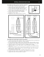
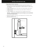
Page 25: ...he remote blower See the Remote blower electrical connection on next page Additional knock outs should be used for the remote blower wiring Install a suitable UL listed strain relief or conduit fitting not included into the knock out Connect the remote blower wiring into the downdraft unit N neutral into the right terminal L1 live into the left terminal and the green ground wire goes into the grou...

Page 26: ...ng box with twist on connector Fig 28 Connect the L1 live wire to the black wire in the wiring box with twist on connector Fig 28 Connect the green power supply ground wire to the green ground screw Attention verify that the main filter flap and wiring box cover are positioned correctly with wiring clearance Replace the wiring box cover and screws taking care not to pinch the wiring under the wiri...

Page 27: ...ws Fig 30 Install the grease filters Fig 31 Check the blower operation If the blower does not work refer to the Troubleshooting section on page 28 9 Attach the ducting For the internal blower box use 6 152 mm round ducting and the 6 152 mm diameter back draft damper For the remote blower use 10 254 mm round ducting Attach ducting using clamps or aluminum duct tape to seal all joints and vent outsi...

Page 28: ...sing the flame away from the spark igniter This may cause the spark to keep running while trying to reignite the burner that is already lit To resolve this and improve burner performance decrease the fan speed or increase the burner setting or both Controls A B CONTROL PANEL FEATURES A Power On Off Push the power button on the top trim the downdraft unit will rise The blower will begin to vent imm...

Page 29: ... month the aluminum grease filters should be removed and cleaned with hot soapy water or in a dishwasher Please note that contact with other items in the dishwasher may cause surface scratching If washed in a dishwasher the filter should be placed in an upright position to prevent food from falling on them After cleaning and drying refit the filters Removing the grease filters 1 Place fingertips i...

Page 30: ...the downdraft unit to remove the water If the downdraft vent system does not operate Check that a circuit breaker has not tripped or a household fuse blown Check that the grease filters are properly installed Check the downdraft unit fuse located under the power board Note this downdraft unit is designed with a microswitch behind the center of each grease filter These microswitches prevent the blo...

Page 31: ...switch in the pair of switches on the bottom of the downdraft unit in front of lower limit switch Fig 33 3 Press and hold the power button with a pointy object on the top right of the downdraft unit Fig 34 4 While holding the power button place a small flat head screwdriver underneath the safety switch to disengage the lever from the safety switch button Fig 35 By pulling this lever away from the ...

Page 32: ...30 PARTS AND ACCESSORIES ITEM REFERENCE NUMBER Internal blower HBD600I Remote blower model HBD1200E Filter HD30 290317 Filter HD36 290334 ...

Page 33: ...31 WIRING DIAGRAM Downdraft unit wiring diagram EN ...

Page 34: ...32 WIRING DIAGRAM Remote blower wiring diagram ...

Page 35: ... during the term of the two year limited warranty Repair as to parts or at its option replace any blower motor which is found to be defective during the term of the additional three year blower motor part only limited warranty You will be responsible for any labor costs In Alaska you must pay to ship the product to the service shop or for the service technician s travel to your home If the product...

Page 36: ...Defects to the product caused by accident neglect misuse fire flood or act of God d The cost of repairs carried out by non authorized repairers or the cost of correcting such unauthorized repairs e Travel fees and associated charges incurred when the product is installed in a location with limited or restricted access e g airplane flights ferry charges isolated geographic areas f Normal recommende...

Page 37: ... will be serviced under these limited warranties No other warranties These limited warranties are the complete and exclusive agreement between you and Fisher Paykel regarding any defect in the product and no other express warranty has been made or will be made on behalf of Fisher Paykel None of our employees or our Authorized Service Agents are authorized to make any addition or modification to th...

Page 38: ......

Page 39: ...les illustrés dans ce guide d utilisation peuvent ne pas être disponibles dans tous les pays et sont sujets à modifications sans préavis Pour les plus récentes informations sur la disponibilité des modèles et des caractéristiques dans votre pays veuillez visiter notre site Web www dcsappliances com ou contacter votre détaillant DCS par Fisher Paykel local Enregistrement Enregistrez votre produit a...

Page 40: ......

Page 41: ...tions au sujet de notre produit communiquez avec un représentant du service à la clientèle de DCS par téléphone 1 888 936 7872 ou par courriel support dcsappliances com Remarque veuillez noter le numéro de modèle le code et le numéro de série sur cette page pour référence ultérieure Numéro de modèle du système de ventilation____________________________________ Code__________________________ Numéro...

Page 42: ...STALLER OU UTILISER CET APPAREIL Les manuels sont également disponibles sur notre site Web www dcsappliances com ATTENTION Utiliser uniquement pour la ventilation générale Ne pas utiliser pour l évacuation de matières ou de vapeurs dangereuses ou explosives MISE EN GARDE Pour réduire les risques d incendie de choc électrique ou de blessures respectez ces consignes Utilisez cet appareil uniquement ...

Page 43: ...Les débordements produisent de la fumée et des déversements de matières grasses qui peuvent s enflammer Chauffez les huiles lentement à feu doux ou moyen Allumez toujours la hotte lorsque vous cuisinez à feu vif ou faites flamber des aliments par ex crêpes Suzette cerise jubilé steak au poivre flambé Nettoyez fréquemment les ventilateurs Ne laissez jamais la graisse s accumuler sur le ventilateur ...

Page 44: ...tance doivent être convertis le plus rapidement possible au format de conduit circulaire de 10 po 254 mm Lors de l utilisation d un conduit de petite taille vous devez le convertir le plus rapidement possible au format circulaire de 10 po 254 mm MISE EN GARDE Pour réduire les risques d incendie utilisez uniquement des conduits en métal ATTENTION Pour réduire les risques d incendie et évacuer l air...

Page 45: ...té du câble d alimentation électrique au niveau de l appareil et de la boîte de jonction Pour effectuer le raccordement électrique découpez un trou de 1 1 4 po 32 mm dans le mur Si le trou est découpé dans le bois vous devrez le sabler jusqu à ce qu il soit lisse Si le trou est découpé dans le métal il devra comporter un œillet IMPORTANT Utilisez cet appareil uniquement de la manière prévue par le...

Page 46: ...m pour ventilateur à distance 1 Filtre à graisses 2 Pièce de fixation pour dessous de comptoir 2 Vis de 3 16 po 5 mm 2 Vis de 5 16 po 8 mm 6 Vis autotaraudeuse de 19 32 po 15 mm 6 Garniture supérieure 1 HD30 and HD36 Vent models HBD600I and HBD1200E Blower models US CA INSTRUCTIONS D INSTALLATION GUIDE D UTILISATION INSTALLATION INSTRUCTIONS USER GUIDE Telescopic Downdraft Vent System Système de v...

Page 47: ...emballage Boîtier de ventilateur interne 1 Clapet anti refoulement d air de 6 po 152 mm de diamètre 1 Ventilateur à distance HBD1200E Contenu de l emballage Ventilateur à distance 1 Plaque avec collet pour conduit 1 INSTRUCTIONS D INSTALLATION FR ...

Page 48: ...ntilation à aspiration descendante Plaque de raccordement pour ventilateur à distance qu il est également possible d installer à l arrière de l appareil Ø10 po 254 mm 13 po 330 mm 13 po 330 mm 5 8 po 16 mm Unité d aspiration descendante et boîtier de ventilateur interne HBD600I qu il est également possible d installer à l arrière de l appareil 13 po 330 mm 13 po 330 mm 1 1 2 po 38 mm 3 8 po 9 5 mm...

Page 49: ...Conduit arrière de 6 po 152 mm du ventilateur interne D Ouverture pour cordon d alimentation du ventilateur à distance dans le bas ou à l arrière E Conduit arrière de 10 po 254 mm du ventilateur à distance F Surface de cuisson en surplomb HD30 HD36 DIMENSIONS D INSTALLATION pouces mm pouces mm G Largeur minimale de la surface de cuisson 28 po 711 34 po 864 H Largeur de l ouverture pour unité d asp...

Page 50: ...onnaître les dimensions et mesures de dégagement adéquates IMPORTANT Assurez vous qu il soit possible d utiliser la surface de cuisson installée avec un système de ventilation à aspiration descendante Exigences relatives à l évacuation Veuillez porter une attention particulière à assurer la conformité à toutes les réglementations relatives à l évacuation de l air Pour une efficacité optimale utili...

Page 51: ...ant la valeur en pieds équivalents indiquée dans le tableau ci dessous pour chaque section de conduit du système complet Lors de l utilisation d un conduit en métal flexible chaque pied 312 mm de conduit en métal flexible équivaut à deux pieds 617 mm de conduit en métal droit pour le calcul de longueur du conduit Pour de meilleurs résultats utilisez un conduit de taille uniforme avec un maximum de...

Page 52: ...unité d aspiration descendante et placez la sur une surface plane protégée Assurez vous que la tension V et la fréquence Hz indiquées sur la plaque signalétique correspondent à la tension et la fréquence sur le site d installation Vérifiez que la section à proximité de la zone d installation ne contient aucun câble électrique tuyau etc Tenez compte de l emplacement des armoires et dosserets dans l...

Page 53: ... à distance L unité d aspiration descendante est prête à l installation avec la plaque de raccordement de 10 po 254 mm pour ventilateur à distance installée à l avant et la plaque de recouvrement installée à l arrière Pour raccorder le ventilateur à distance à la partie arrière de l unité d aspiration descendante changez les plaques voir Fig 3 et 4 Installez les pièces de fixation pour dessus de c...

Page 54: ... peut entraîner des dommages à la surface du comptoir Fig 5 Mettez de niveau et alignez l unité d aspiration descendante dans l armoire Poussez la pièce de fixation avec patte de soutien de chaque côté contre le fond de l armoire Marquez le rebord supérieur de la pièce de fixation sur l unité d aspiration descendante et les trous de montage sur le fond de l armoire Fig 6 4 Retirez l unité d aspira...

Page 55: ... à la section Préparation pour le raccordement électrique à la page 57 A V A N T Fig 8 Fig 7 Option 2 Ventilateur interne installation par l avant pour évacuation vers l arrière Pour l option d évacuation vers l arrière avec le ventilateur interne installé à l avant de l unité d aspiration descendante vous devez repositionner le boîtier de ventilateur Retirez les deux vis et enlevez le ventilateur...

Page 56: ...teur interne peut également être installé à l arrière de l unité d aspiration descendante pour permettre l installation d une cuisinière ou d un four mural une surface de cuisson devant l unité d aspiration descendante Retirez le grand couvercle situé à l arrière de l unité d aspiration descendante Fig 16 Tournez le collet de conduit du boîtier de ventilateur dans la direction souhaitée vers la ga...

Page 57: ...4 mm sur le mur comme indiqué dans la Fig 19 Découpez une ouverture rectangulaire dans le bardage seulement Ne découpez pas le revêtement Clouez toutes les extrémités de bardage Marquez un cercle de 11 po 279 mm de diamètre autour du trou de guidage comme indiqué dans la Fig 19 Marquez le centre du trou de 1 1 4 po 32 mm de diamètre pour le câblage électrique comme indiqué dans la Fig 19 Découpez ...

Page 58: ...de de vis appropriées pour votre installation Bouchez les quatre trous dans le panneau arrière pour éviter que l humidité puisse pénétrer dans la maison en s infiltrant par le compartiment du ventilateur à distance Scellez tous les bardeaux autour du compartiment de ventilateur à distance le revêtement pour solin et les têtes de vis de montage ou la charpente à l aide de goudron de toiture La brid...

Page 59: ...e défonçable Fig 22 Si l unité d aspiration descendante est installée avec un ventilateur à distance retirez l alvéole défonçable pour le câble de commande Avec l aide d une autre personne soulevez l unité d aspiration descendante dans l ouverture que vous avez préparée dans l armoire Les pièces de fixation pour dessus de comptoir doivent reposer sur le comptoir Fixez l unité d aspiration descenda...

Page 60: ...it être raccordée uniquement à l aide de fil de cuivre Les calibres de fil doivent être conformes aux exigences de la norme ANSI NFPA70 de la dernière édition du Code national de l électricité ainsi qu à tous les codes et règlements locaux en vigueur Le calibre de fil et les raccordements doivent être conformes aux caractéristiques de l appareil Des copies de la norme mentionnée ci dessus peuvent ...

Page 61: ...électrique du ventilateur à distance de l unité d aspiration descendante Connectez le câble d alimentation électrique à la boîte de jonction de la manière décrite dans la section Raccordement électrique du ventilateur interne de l unité d aspiration descendante ci dessus Pour utiliser un ventilateur à distance installez un câble de contrôle entre l unité d aspiration descendante et le ventilateur ...

Page 62: ... 28 Connectez le fil L1 sous tension au fil noir dans le boîtier de câblage à l aide d un capuchon de connexion Fig 28 Connectez le fil vert de mise à la terre du câble d alimentation électrique à la vis verte de mise à la terre Attention vérifiez que le filtre le rabat et le couvercle sont positionnés correctement et assure une clairance avec le câblage Réinstallez le couvercle du boîtier de câbl...

Page 63: ...Fig 31 Vérifiez le fonctionnement du ventilateur Si le ventilateur ne fonctionne pas reportez vous à la section Dépannage à la page 64 9 Fixez le conduit Pour le boîtier de ventilateur interne utilisez un conduit circulaire de 6 po 152 mm et le clapet anti refoulement d air de 6 po 152 mm de diamètre Pour le ventilateur à distance utilisez un conduit circulaire de 10 po 254 mm Fixez le conduit à l...

Page 64: ...spositif d allumage par étincelle Le dispositif pourrait alors continuer de produire une étincelle pour tenter de rallumer le brûleur déjà allumé Pour résoudre ce problème et améliorer les performances du brûleur réduisez la vitesse du ventilateur augmentez le réglage du brûleur ou essayez ces deux solutions en même temps Commandes A B FONCTIONNALITÉS DU PANNEAU DE COMMANDE A Mise en marche arrêt ...

Page 65: ...er les filtres à graisses en aluminium pour les nettoyer avec de l eau savonneuse et chaude ou dans un lave vaisselle Veuillez noter que le contact avec d autres articles dans le lave vaisselle pourrait égratigner leur surface Si vous les lavez au lave vaisselle vous devez placer les filtres dans une position verticale pour éviter que des aliments se déposent sur ceux ci Après le nettoyage et le s...

Page 66: ...ue N ouvrez pas l unité d aspiration descendante pour enlever l eau Si le système de ventilation à aspiration descendante ne fonctionne pas Vérifiez qu aucun disjoncteur n est déclenché ou qu aucun fusible de la maison n est grillé Vérifiez que les filtres à graisses sont correctement installés Vérifiez le fusible de l unité d aspiration descendante situé sous le circuit d alimentation Remarque ce...

Page 67: ... dans le bas de l unité d aspiration descendante devant l interrupteur de limite inférieure Fig 33 3 Maintenez enfoncée à l aide d un objet pointu la touche d alimentation située dans la partie supérieure droite de l unité d aspiration descendante Fig 34 4 Pendant que vous maintenez enfoncée la touche d alimentation placez un petit tournevis à tête plate sous l interrupteur de sécurité pour dégage...

Page 68: ...66 PIÈCES ET ACCESSOIRES ARTICLE NUMÉRO DE RÉFÉRENCE Ventilateur interne HBD600I Modèle de ventilateur à distance HBD1200E Filtre HD30 290317 Filtre HD36 290334 ...

Page 69: ... NOIR GRIS B L J V BRUN ORANGE BRUN VENTILATEUR À DISTANCE BLEU B L BRUN ORANGE ORANGE NOIR 220 240 V 50 Hz 200 V 60 Hz 110 127 V 60 Hz F N M8 4V BLEU MOTEUR LUX2 AUX LUX1 Faber ATF BLEU ORANGE ORANGE GRIS INTERRUPTEURS DE LIMITE INFÉRIEURE N O INTERRUPTEURS DE LIMITE SUPÉRIEURE N O INTERRUPTEUR DE FILTRE N 1 INTERRUPTEUR DE FILTRE N 2 INTERRUPTEUR DE FILTRE N 3 INTERRUPTEUR DE SÉCURITÉ INFÉRIEUR ...

Page 70: ...68 SCHÉMA DE CÂBLAGE Schéma de câblage du ventilateur à distance VENTILATEUR À DISTANCE NOIR BRUN BRUN NOIR BLEU NOIR VERT BLANC BRUN VERT BLEU BOÎTIER DE CÂBLAGE ...

Page 71: ...aines exceptions décrites aux présentes toute pièce s avérant défectueuse du produit dont le numéro de série figure sur celui ci pendant la période de garantie limitée de deux ans Réparer dans le cas des pièces ou à sa discrétion remplacer tout moteur de ventilateur s avérant défectueux pendant la période de garantie limitée supplémentaire de trois ans s appliquant uniquement aux pièces du moteur ...

Page 72: ...1 Utilisation domestique normale ou 2 Utilisation en conformité avec le guide d utilisation du produit c Défectuosités du produit causées par un accident la négligence une utilisation inappropriée un incendie une inondation ou une catastrophe naturelle d Les frais des réparations effectuées par des réparateurs non autorisés ou les frais associés à la correction de telles réparations non autorisées...

Page 73: ...de ces garanties limitées Aucune autre garantie Ces garanties limitées constituent la totalité de l accord exclusif existant entre l acheteur et Fisher Paykel relativement à toute défectuosité de ce produit aucune autre garantie expresse n est offerte ou ne sera offerte au nom de Fisher Paykel Aucun de nos employés ou agents de service autorisés n est autorisé à effectuer des ajouts ou apporter de...

Page 74: ......

Page 75: ......

Page 76: ...ler to ensure this booklet correctly describes the product currently available Fisher Paykel Appliances 2016 Tous droits réservés Les caractéristiques de produit présentées dans ce livret s appliquent aux modèles et produits spécifiques qui y sont décrits à la date de publication Dans le cadre de notre politique d amélioration en permanence de nos produits ces caractéristiques peuvent être modifié...

Reviews: