background image

D

IGITAL  

C

ONTROL  

I

NCORPORATED


14


DigiTrak MFCB Operator’s Manual 

Appendix B: Transmitter Wire Repair or 
Replacement 

The cable lead and other end cap components in the cable transmitter must be replaced 
when the wire shows wear, twists, or abrasions. This involves removing the transmitter end 
cap to access the cable lead connection to the transmitter base. The Replaceable Wire Kit 
(DCKIT) includes enough parts to replace the cable lead two times. You will also need a 
standard screw driver. 

The DCKIT contains: 

  Two cable leads 

  Four Torx screws 

  Four lock washers  

  Four 2-021 O-rings 

  Two screw insulators 

  Two 2-106 O-rings 

  Two brass set screws 

  Three white nylon set screws 

  One T15 Torx wrench  

  One each 

5

/

64

”, 

1

/

8

”, and 

3

/

32

” Allen wrenches 

  One tube of Noalox anti-oxidant compound 

To disassemble and reassemble the transmitter end cap: 

2.  Using the 

5

/

64

” Allen wrench or the T15 Torx wrench, depending on the screw type 

installed, remove the two Torx or buttonhead cap screws and lock washers. 

3.  Pull the end cap from the transmitter base. 

4.  Identify the deepest set screw depression in the base. Using the 

1

/

8

” Allen wrench or 

a standard screw driver, remove the white nylon set screw. There will be a brass set 
screw behind the nylon screw that holds the cable in place. 

5. 


Note 

Do not tamper with the brass set screw and O-ring located on the opposite 
side of the base in the shallow depression.


6.  Using the 

3

/

32

” Allen wrench, remove the brass set screw inside the transmitter base 

that holds the cable lead to the base. 

7.  Remove the old wire, the 2-106 O-ring, and the screw insulator. Removing the old 

wire from the base may require some force. 

8.  Install a new insulator and 2-106 O-ring onto a new cable lead, and insert the wire in 

the base. Ensure only 

5

/

16

” of the wire coating is stripped back from the end of the 

tinned cable lead. 

9.  Install a new brass set screw using the 

3

/

32

” Allen wrench. Push the cable lead in 

while tightening the set screw to ensure a good connection. 

10.  Using the standard screw driver or the 

1

/

8

” Allen wrench, install a new white nylon set 

screw into the side of the transmitter base. 
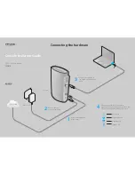
Transmitter 

end cap 

Threaded hole for 

extraction/insertion 

tool (two) 


Torx or  

buttonhead cap 

screws (two) 

Transmitter 

body 

Wire End of Transmitter 

Summary of Contents for DigiTrak MFCB

Page 1: ...DIGITAL CONTROL INCORPORATED dci digital control com www DigiTrak com MFCB Multi Function Cable Box Operator s Manual...

Page 2: ...n shall constitute any warranty by DCI nor will anything herein be deemed to modify the terms of DCI s existing Limited Warranty applicable to all DCI products The most recent version of this manual i...

Page 3: ...China 368 Xingle Road Huacao Town Minhang District Shanghai 201107 P R C 86 21 6432 5186 86 21 6432 5187 fax dci china digital control com Europe Brueckenstra e 2 97828 Marktheidenfeld Germany 49 9391...

Page 4: ...253 395 2800 or complete and submit the form online at our website www digitrak com We will put you on the Digital Control mailing list and send you product upgrade information and our FasTrak newsle...

Page 5: ...ring for Your Transmitter 3 Introduction 4 MFCB Connections 5 Powering the MFCB 6 Connecting to the Remote Display 7 Connecting to the Cable Transmitter 8 Installing Transmitter in Housing 9 Cable Mod...

Page 6: ...DIGITAL CONTROL INCORPORATED vi DigiTrak MFCB Operator s Manual...

Page 7: ...rectly to obtain proper performance DCI equipment is not explosion proof and should never be used near flammable or explosive substances In the event of electrostatic shock the display screen may go b...

Page 8: ...ned with adequate safeguards to protect you from shock and other hazards when used as specified within this document If you use the battery charger in a manner not specified by this document the prote...

Page 9: ...for Your Cable Box Do not disassemble The cable box contains no user serviceable parts Clean exterior with a damp cloth Do not submerge Do not pressure wash Ensure all ports remain clean and clear of...

Page 10: ...ies are not available from DCI Drill manufacturers or tooling manufacturers will have information on collector ring slip ring assemblies mud swivels and compression fittings Electrical supply houses w...

Page 11: ...hough the DC power cable used to power a freestanding multi function display through the power port on the drill rig can power the cable box DCI recommends connecting the cable box directly to an inde...

Page 12: ...connector clockwise until it locks into place with a snapping sound Connect the other end of the power cable to the DC power source When using the cable with the bare wires at one end recommended conn...

Page 13: ...display use the cable with identical four hole round connectors at both ends Align the key marks in the connector with the key slots in one of the power ports then push in and rotate the connector clo...

Page 14: ...en the cable transmitter is properly fitted into a housing the ground connection occurs automatically because the housing is grounded through the drill When testing the cable transmitter outside of a...

Page 15: ...FC ECP Transmitter Housing Slot Requirements The SST cable transmitter 24 in 60 96 cm long requires a non magnetic housing The slots in the housing must be at least 9 in 22 9 cm long and begin at lea...

Page 16: ...cable mode option you may need a software upgrade please contact DCI Customer Service Remote Display Main Menu with Cable Mode Highlighted Cable Mode Display Screen A cable transmitter is identified o...

Page 17: ...manual and the remote display To access roll offset on the remote display push the right direction button while in the Cable Mode screen The roll offset popup menu appears with three options Exit Go...

Page 18: ...et to program the roll offset to the displayed value Roll Offset Menu Disable or Set X Exit Exits the roll offset menu without saving changes Stop Disables roll offset Set Sets the displayed value as...

Page 19: ...DigiTrak Remote F Series Display FSD 12 28 V 3 2 W max DigiTrak Eclipse and F Series Cable Transmitter ECP FC 9 28 V 6 A max DigiTrak Eclipse Steering Tool SST 9 28 V 6 A max Environmental Requiremen...

Page 20: ...r base 4 Identify the deepest set screw depression in the base Using the 1 8 Allen wrench or a standard screw driver remove the white nylon set screw There will be a brass set screw behind the nylon s...

Page 21: ...he base with a thin layer of Noalox to prevent electrical corrosion Do not substitute standard grease 13 Replace end cap and line up the screw holes on the base with the unthreaded holes on the cap 14...

Page 22: ...DIGITAL CONTROL INCORPORATED 16 DigiTrak MFCB Operator s Manual...

Page 23: ...below WHAT IS NOT COVERED This Limited Warranty excludes all damage including damage to any DCI Product due to failure to follow DCI s operator s manual and other DCI instructions abuse misuse neglect...

Page 24: ...have all related equipment available together with a list of all DCI Product serial numbers It is important that field troubleshooting be conducted because many problems do not result from a defective...

Reviews: